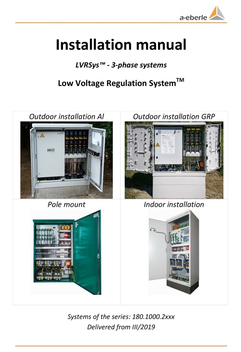
a-eberle LVRSys User manual

User Manual
LVRSys™ - 3-phase / 1-phase Systems
Low-Voltage-Regulation-System™
Outdoor Al
Outdoor GRP
Pole mounted
Indoor
Systems of the series: 180.1000.2xxx
Delivery from 2017 and FW-Version 12.00.05 / 12.01.00

Content
We take care of it.
Content
1. User guidance ................................................................................................................ 1
1.1 Target group..............................................................................................................................1
1.2 Warnings ...................................................................................................................................1
1.3 Tips............................................................................................................................................1
1.4 Other symbols...........................................................................................................................2
1.5 Applicable documentation........................................................................................................2
1.6 Keeping .....................................................................................................................................2
2. Scope of Delivery/Options (PL1.9) .................................................................................. 3
3. Configuration possibilities .............................................................................................. 3
4. Safety instructions ......................................................................................................... 3
5. Technical Data ............................................................................................................... 4
6. Intended use.................................................................................................................. 7
7. Description and Principle of Operation ........................................................................... 7
7.1 Principle of Operation...............................................................................................................7
7.2 Operating behavior in the low-voltage grid........................................................................... 10
7.3 Voltage drop with load........................................................................................................... 11
7.4 Voltage boost with generator (e. g. PV feeder) ..................................................................... 12
8. Commissioning and Decommissioning LVRSys™ .............................................................13
8.1 Indicator lamps & system switch ........................................................................................... 13
8.2 Commissioning and decommissioning LVRSys™.................................................................... 13
8.3 Check that there is no voltage present.................................................................................. 15
8.4 Operation of circuit breakers and switch-disconnectors....................................................... 15
Operation of systems with circuit breakers........................................................................... 158.4.1
Operation of systems with switch disconnectors.................................................................. 178.4.2
Operation of systems with LV fuse-switch-disconnectors..................................................... 198.4.3
9. Operation/Operation regulator .....................................................................................21
9.1 Indicator lamps/System switches .......................................................................................... 21
9.2Indicator lamps & switch service –CPU board (A7)............................................................... 21
9.3 Indicator lamps –Control cabinet.......................................................................................... 22
9.4 Switches ................................................................................................................................. 22
9.5 Boot process .......................................................................................................................... 23
9.6 Menu navigation .................................................................................................................... 23
9.7 Automatic mode .................................................................................................................... 24
9.8 Manual mode......................................................................................................................... 24
9.9 Overview display.................................................................................................................... 25

Content
9.10 Parameters..............................................................................................................................26
Set point..................................................................................................................................279.10.1
Tolerance band + and tolerance band -..................................................................................279.10.2
Reaction time..........................................................................................................................289.10.3
Impedance ..............................................................................................................................299.10.4
Balancing (Bal. active).............................................................................................................309.10.5
Overvoltage warning...............................................................................................................309.10.6
Undervoltage warning ............................................................................................................319.10.7
9.11 Setup.......................................................................................................................................31
Communication.......................................................................................................................319.11.1
Security ...................................................................................................................................31
9.11.2
Date.........................................................................................................................................319.11.3
Time ........................................................................................................................................319.11.4
Language.................................................................................................................................329.11.5
9.12 Device Info ..............................................................................................................................32
USB..........................................................................................................................................329.12.1
Firmware update ....................................................................................................................329.12.2
Logbook...................................................................................................................................349.12.3
Firmware-Version ...................................................................................................................419.12.4
LOG ERR ..................................................................................................................................419.12.5
Type number...........................................................................................................................429.12.6
9.13 Factory settings.......................................................................................................................42
Step width...............................................................................................................................439.13.1
Network frequency .................................................................................................................439.13.2
CT ratio (current transformer ratio) .......................................................................................439.13.3
Resetting the indicator ...........................................................................................................449.13.4
Clear statistics.........................................................................................................................449.13.5
T104 licensing .........................................................................................................................449.13.6
10. Communication............................................................................................................ 45
10.1 Ethernet ..................................................................................................................................45
10.2 Overview communication settings .........................................................................................45
10.3 TCP/IP Configuration via Ethernet..........................................................................................46
10.4 Modbus...................................................................................................................................46
Modbus Setup.........................................................................................................................4610.4.1
Modbus register assignment ..................................................................................................4710.4.2
10.5 IEC 60870-5-104......................................................................................................................50
Unlock IEC 60870-5-104 License.............................................................................................5010.5.1

Content
We take care of it.
CSV configuration of the IEC 60870-5-104 Slave ................................................................... 5110.5.2
IEC 60870-5-104 Parameters ................................................................................................. 5110.5.3
Redundancy System............................................................................................................... 5210.5.4
Process information for monitoring ...................................................................................... 5310.5.5
Process information for control............................................................................................. 5310.5.6
IEC 60870-5-104 register assignment .................................................................................... 5410.5.7
10.6 NTP Time Synchronization ..................................................................................................... 57
10.7 Further protocols ................................................................................................................... 57
11. IT-Security.....................................................................................................................58
12. External devices & modifications ...................................................................................59
12.1 External devices ..................................................................................................................... 59
12.2 PQI-DA smart ......................................................................................................................... 59
13. Servicing/Cleaning/Spare parts......................................................................................60
14. Standards and Laws (all based on European standards)..................................................60
15. Disassembly & disposal .................................................................................................60
16. Warranty ......................................................................................................................61

Page 1
1. User guidance
This User Manual is a summary of the information needed for the installation,commisioning
and operation of the low-voltage regulator.
Read the User Manual in its entirety and do not use the product unless you have
understood the User Manual.
1.1 Target group
The User Manual is intended for skilled technicians as well trained and certified operators.
The contents of this User Manual must be accessible to people tasked with the installation
and operation of the system.
1.2 Warnings
Structure of the warnings
Warnings are structured as follows:
SIGNAL WORD
Nature and source of the danger.
Consequences of non-compliance.
Actions to avoid the danger.
Types of warnings
Warnings are distinguished by the type of danger they are warning against:
DANGER!
Warns of imminent danger that can result in death or serious injuries
if not avoided.
WARNING!
Warns of a potentially dangerous situation that can result in death or
serious injuries when not avoided.
CAUTION!
Warns of a potentially dangerous situation that can result in
fairly serious or minor injuries when not avoided.
NOTICE:
Warns of a potentially dangerous situation that if not avoided
could result in material or environmental damage.
1.3 Tips
Tips on the appropriate device use and recommendations.

Page 2
We take care of it.
1.4 Other symbols
Instructions
Structure of the instructions:
Instructions for an action.
Indication of an outcome, if necessary.
Lists
Structure of unnumbered lists:
0List level 1
–List level 2
Structure of numbered lists:
1) List level 1
2) List level 1
1. List level 2
2. List level 2
1.5 Applicable documentation
For the safe and correct use of the product, observe the additional documentation that is
delivered with the system as well as the relevant standards and laws.
1.6 Keeping
Keep the user manual, including the supplied documentation, readily accessible near the
system.

Page 3
2. Scope of Delivery/Options (PL1.9)
The LVRSys systems are built up as modular systems. The main components and documents
are:
0LVRSys™ control unit
0Transformer block
0Cabinet for out- or indoor installation or pole mount
0LVRSys™ user manual
0LVRSys™ mounting instructions
0Circuit diagram of the LVRSys™control cabinet
0LVRSys™ test certificate
3. Configuration possibilities
The possibities of how an LVRSys can be configured cab be found in the Configuration help
LVRSys in coorespondense with the sales partners:
https://www.a-eberle.de/en/contact/partners
4. Safety instructions
Observe the operating instructions
Always keep the operating instructions with the unit.
Make sure that the device is never operated in a damaged or compromised condition.
Make sure that only specialized personnel operate the unit.
The device must be connected according to the manufacturer’s installation instructions.
Make sure that the device is never operated beyond its stated ratings (refer chapter 5,
Technical Data)
Do not operate the unit in any hazardous environment where explosive gases, dust or
fumes occur.
Ensure that protective covers are always in place and are functional
Ensure that the five safety regulations according to DIN VDE 0105 are always observed.
Clean the appliance only with commercially available detergents.

Page 4
We take care of it.
5. Technical Data
Rated data
Rated voltage 𝐔𝐍
400 V / 230 V ±20 % (L-L/LE)
230 V / 133 V ±20 % (L-L/LE)
Rated current 𝐈𝐍
3-phase (400 V L-L)
32 A (22 kVA System)
63 A (44 kVA System)
100 A (70 kVA System)
160 A (110 kVA System)
200 A (144 kVA System)
250 A (175 kVA System)
290 A (200 kVA System)
355 A (250 kVA System)
577 A (400 kVA System)
910 A (630 kVA System)
1005 A (696 kVA System)
1-phase (230 V L-N)
32 A (7,5 kVA System)
63 A (15 kVA System)
100 A (25 kVA System)
160 A (35 kVA System)
3-phase (230 V L-L)
32 A (13 kVA System)
63 A (26 kVA System)
100 A (41 kVA System)
160 A (64 kVA System)
200 A (84 kVA System)
250 A (101 kVA System)
290 A (116 kVA System)
355 A (145 kVA System)
577 A (231 kVA System)
910 A (364 kVA System)
1005 A (400 kVA System)
Rated frequency 𝐟𝐍
50 Hz / 60 Hz
Efficiency
99.4 % –99.8 %
Maximum regulation time
30 ms
Regulation area
± 6 % from UNin 9 steps á 1.5 %
± 8 % from UNin 9 steps á 2.0 %
± 10 % from UNin 9 steps á 2.5 %
up to ± 24 % from UN(special design)
Ambient temperature
- 40 °C to + 40 °C (to + 50 °C special design)
Maximum permissible air temperature
in the cabinet
70 °C
Height of installation (NN)
< 2000 m
Protection class
IP44- IP55/ electronic IP 66
Maximum current consumption sec-
ondary electronics
200 mA (230 V)
Short-circuit impedance 𝐮𝐤
ca. 0,3 %
Cooling
Passive (Convection via cabinet housing)

Page 5
Limits
Rated impulse voltage 𝐔𝐈𝐦𝐩
6 kV
Rated short-time current resistance
𝐈𝐜𝐰 ( 1 s)
5 kA (till 160 A)
15 kA (200 A till 1005 A)
Conditional rated short-circuit current
𝐈𝐜𝐜
20 kA (to 160 A)
50 kA (200 A till 1005 A)
Rated short-circuit current 𝐈𝐜𝐟
protected by fuse
3 kA (32 A)
5 kA (63 A)
10 kA (100 A)
14 kA (160 A)
16 kA (200 A)
20k A (250 A)
30 kA (355 A)
50 kA (580 A)
50 kA (910 A)
50 kA (1005 A)
Rated impulse current resistance 𝐈𝐩𝐤
20 kA (to 160 A)
50 kA (200 to 1005 A)
Dimensions and weight
Dimensions cabinet
B/T/H
Aluminium cabinet
GRP –Cabinet
Indoor cabinet
Pole mounted 3-phase
80 cm/40 cm/135 cm
120 cm/40 cm/135 cm
140 cm/50 cm/145 cm
160 cm/50 cm/155 cm
113 cm/32 cm/113 cm
146 cm/32 cm/113 cm
60 cm/60 cm/160 cm
90 cm/60 cm/200 cm
80 cm/30 cm/120 cm
32 A –100 A
32 A –355 A 8 %
32 A –580 A
32 A –910 A
32 A –160 A
32 A –355 A 8 %
32 A –160 A
200 A –580 A
32 A –100 A
B11
B12
B13
B14
B41
B42
B21
B22
PM
Weight cabinet
Aluminium cabinet
GRP –Cabinet
Indoor cabinet t
Pole mounted 3-phase
Pole mounted 1-phase
120 kg
165 kg
220 kg
250 kg
100 kg
155 kg
150 kg –200 kg
300 kg –700 kg
110 kg –130 kg
40 kg –60 kg
32 A –100 A
32 A –355 A 8 %
32 A –580 A
32 A –910 A
32 A –160 A
32 A –355 A 8 %
32 A –160 A
200 A –580 A
32 A –100 A
32 A –160 A
B11
B12
B13
B14
B41
B42
B21
B22
PM
PM
Measurement base
B/T/H
Concrete base
80 cm/40 cm/100 cm
120 cm/40 cm/100 cm
140 cm/50 cm/100 cm
32 A –100 A
32 A –355 A 8 %
32 A –580 A
C11
C12
C13

Page 6
We take care of it.
GRP - Base
Steel base indoor (pre-
assembled)
160 cm/50 cm/100 cm
113 cm/32 cm/90 cm
146 cm/32 cm/90 cm
60 cm/60 cm/20 cm
90 cm/60 cm/20 cm
32 A –910 A
32 A –160 A
32 A –355 A 8 %
32 A –160 A
200 A –580 A
C14
C41
C42
C21
C22
Weight base
Concrete base
GRP –base
Steel base indoor (pre-
assembled)
200 kg
260 kg
280 kg
300 kg
30 kg
40 kg
5 kg
10 kg
32 A –100 A
32 A –355 A 8 %
32 A –580 A
32 A –910 A
32 A –160 A
32 A –355 A 8 %
32 A –160 A
200 A –580 A
C11
C12
C13
C14
C41
C42
C21
C22
Measurement trans-
former block B/T/H –
3-phase
40 cm/20 cm/ 85 cm
50 cm/22 cm/ 85 cm
70 cm/30 cm/ 95 cm
70 cm/39 cm/105 cm
32 A –160 A
200 A –355 A 8 %
355 A 10 % –580 A
910 A
Weight transformer
block –3-phase
110 - 125 kg ( 32 A)
125 - 135 kg ( 63 A)
130 - 190 kg ( 100 A)
190 - 215 kg (160 A)
190 - 330 kg (200 A)
290 - 330 kg (175 kVA)
315 - 370 kg (355 A)
370 - 610 kg (580 A)
400 - 680 kg (910 A)
Fulfilled guidelines
EMC Immunity
DIN EN 61000-6-1
EMC emissions
DIN EN 61000-6-3
Installation instructions
DIN EN 61439-1/5
Low voltage directive
2014/35/EU
Noise emission
< 37 dB(A)
Integrated Power Quality –measure-
ment
PQI-DA smart (showing connections)


Page 7
6. Intended use
This product is designed exclusively to regulate voltage at the low voltage level (400V L-L
and special applications 230 V L-L).
7. Description and Principle of Operation
7.1 Principle of Operation
The LVRSys™ regulator concept is based on a linear regulator. By coupling and uncoupling
two transformers with a selected transfer ratio, the output voltage can be regulated in
several (e.g. 9) steps. This technique is also refered to as Buck/Boost transformers
The maximum control range depends on the model of LVRSys (e.g. from ±6% up to ±24%).
The switching of the transformers is controlled by thyristors. The regulation steps are
determined by the thyristors' various switching settings.
Step
Transformer 1.5%
Transformer 4.5%
+6 %
+1,5 %
+4,5 %
+4,5 %
0 %
+4,5 %
+3 %
-1,5 %
+4,5 %
+1,5 %
+1,5 %
0 %
0 %
0 %
0 %
-1,5 %
-1,5 %
0 %
-3 %
+1,5 %
-4,5 %
-4,5 %
0 %
-4,5 %
-6 %
-1,5 %
-4,5 %
Table 7-1 Generation of the voltage levels in steps
The control signals for the thyristors are generated by driver circuits that switch them
intelligently. By monitoring the magnetic flux in the transformers, the transformers can be
switched without any voltage dips or current increases occuring or harmonics being
generated.
The step change required is output by the controller. The controller can determine the step
based on the bus bar voltage or the output currents.
All three phases are regulated independently of one another. This greatly helps improve the
symmetry –balancing of the 3 phases of the LV Network.
In the event of a failure the safety contactor activates automatically. This ensures that the
transformers are bridged out and as such the low-voltage grid will operate unregulated.

Page 8
We take care of it.
Figure 7-1 Single-phase functional diagram
Trafo 1
Additional transformer 1
Trafo 2
Additional transformer 2
F1, F2
Fuse
S
Safety contactor
R
Switching resistor
T
Thyristors
TC
Thyristors control
V_in
Unregulated input voltage
V_out
Regulated output voltage
Table 7-2 Explanation of the abbreviations

Page 9
Figure 7-2 Example of 3% voltage reduction
In the example shown in Figure 7-2, the output voltage is reduced by 3% compared with the
input voltage.
The transformer Trafo 1 (-4.5%) converts the primary voltage, which is switched by
thyristors, in a negative direction and subtracts (bucks) 10.35 V (4.5% of 230 V) from the
output voltage.
The transformer Trafo 2 (+1.5%) converts the primary voltage in a positive direction and
adds (boosts) 3.45 V (1.5% of 230 V) to the output voltage.

Page 10
We take care of it.
7.2 Operating behavior in the low-voltage grid
The low-voltage regulation systems are designed for a long, robust use in the low-voltage
grid. In the following, grid scenarios are compared with the behavior of the low voltage
regulation systems.
Event
reaction LVRSys™
Short circuit Ph1
Fuse blow off Ph1
Automatic bypass activated for all phases
Automatic restart of the controller after replacing the
fuse
Short circuit
Ph2/Ph3
Fuse blow off Ph2/Ph3
Automatic bypass activated for all phases.
Automatic operation mode of the controller after replac-
ing the fuse
Lightning strike
All phases
Lightning protection activated
Only after several lightning strikes releases lightning rod
and separates the control system from the main voltage.
Automatic restart of the controller after replacement of
the lightning arrestor module
Voltage drop Phase
1
No reaction of the controller up to 100 V residual volt-
age. Below 100 V residual voltage, the controller goes
into automatic bypass mode
When the voltage returns, the controller automatically
switches to operating mode
Voltage drop
Phase 2/3
No reaction of the controller to 5% residual voltage. Be-
low 5% residual voltage for> 20 ms, the controller goes
into automatic bypass mode. After the voltage has re-
turned to normal, the controller automatically switches to
operating mode
Overvoltage Phase
1/2/3
No reaction of the controller up to 170% residual voltage.
Over 170% residual voltage for> 30 ms, the controller
goes into automatic bypass mode. After the voltage has
returned to normal, the controller automatically switches
to operating mode
Harmonics
harmonics have no influence on the controller
The Controller has no influence on the harmonics.
Flicker
Flicker does not affect the controller
The controller does not affect the ripple flicker values.
Ripple control sig-
nal
Ripple control signal has no influence on the controller
Controller has no influence on ripple control signals
Figure 7-3 System reaction after events

Page 11
7.3 Voltage drop with load
Figure 7-4 Low voltage grid with voltage drop along the cable
Figure 7-5 Low voltage grid with voltage drop along the cable (example)
Figure 7-6 Low voltage grid with voltage drop along the cable regulated through LVRSys
[Simulation Screenshots made with Neplan®].

Page 12
We take care of it.
7.4 Voltage boost with generator (e. g. PV feeder)
Figure 7-7 Low voltage grid with voltage boost along the cable
Figure 7-8 Low voltage grid with voltage boost along the cable (example)
Figure 7-9 Low voltage grid with voltage boost along the cable regulated through LVRSys
[Simulation Screenshots made with Neplan®].

Page 13
8. Commissioning and Decommissioning LVRSys™
8.1 Indicator lamps & system switch
Figure 8-1 Indicator lamps and system switch
Figure 8-2 Switch position
8.2 Commissioning and decommissioning LVRSys™
For operating the LVRSysIN, LVRSysOUT and BYPASS switching elements, observe chapter .
The starting position is:
0Closed BYPASS (F3).
0Opened input (F1 / LVRSys-IN).
0Opened output (F5 / LVRSys-OUT ).
0The controller is in the OFF state.
DANGER!
Danger of electric shock!
Ensure that the LVRSys™ is only operated and commissioned by quali-
fied electricians or persons trained in electrical engineering in
accordance with VDE 0105-100 or certified with respect to the local
wiring and safety regulations applicable in your country.
Never open NH-switch disconnectors/-isolators/circuit breakers
partially
Only operate the NH-switch disconnectors/-isolators/circuit
breakers by using the handle
CAUTION!
Destruction of components due to overload!
Only switch the LVRSys™ ON or OFF according to the sequence of
actions described below.
Never use BYPASS-separation terminals while the system is in
CONTROL - mode.

Page 14
We take care of it.
Commissioning LVRSys™
BYPASS -
mode
CONTROL -
mode
Sequence:
1. Close LVRSys-IN
(with knives/fuses).
2. Close LVRSys-OUT
(with knives/fuses).
3. Open BYPASS
(remove knives).
4. Set the system switch to the ON posi-
tion.
The regulator starts up automatically.
LVRSys™ is active.
The local network is regulated by the
LVRSys™.
Decommissioning LVRSys™ BYPASS
BYPASS -
mode
CONTROL -
mode
Sequence:
1. Set the systems switch to the OFF posi-
tion.
Wait until secondary electronics are
de-energised.
(Display goes out after approx. 10 s).
2. Close BYPASS (with knives).
3. Open LVRSys OUT (remove
knives/fuses).
4. Open LVRSys IN (remove knives/fuses).
The LVRSys™ is completely disconnect-
ed from the network.
BYPASS is active.
The network is supplied via the BYPASS.
Check that there is no voltage present
(Chap. 8.3)
Connection
from
Transformer
LVRSys IN
LVRSys™
Regulation
LVRSys OUT
BYPASS
System switch
OFF
LVRSys IN
LVRSys OUT
System switch
ON
LVRSys™ in BYPASS - mode LVRSys™ in CONTROL - mode
CONTROL -
mode
Connection
from
Transformer
Connection
towards
Load
Connection
towards
Load
LVRSys™
Regulation BYPASS
Figure 8-3 Circuit principle Bypass and operation

Page 15
8.3 Check that there is no voltage present
DANGER!
Danger of electric shock!
Check that there is no voltage on the system input.
Check that there is no voltage on the system output.
Only measure with fused measuring devices with overvoltage
category IV.
0Check there is no voltage at the input (LVRSys-IN).
0Check there is no voltage at the output (LVRSys-OUT).
0Systems with circuit breakers:
Check there is no voltage measured on L1/L2/L3 (directly at the circuit breaker)
with respect to PEN/PE rail.
0Systems with NH switch-disconnectors:
Check there is no voltage measured on L1/L2/L3 (directly at the outlet switch-
disconnectors) with respect to PEN/PE rail.
0Systems with NH fuse-switch-disconnectors:
Check there is no voltage on L1/L2/L3 (directly on the outlet switch disconnector) with
respect to PEN/PE rail.
8.4 Operation of circuit breakers and switch-disconnectors
Operation of systems with circuit breakers8.4.1
When switching the devices, the following must be observed:
Ensure that commissioning, decommissioning and operation are only carried out by
qualified electricians or persons trained in electrical engineering in accordance with
VDE 0105-100 or certified with respect to the local wiring and safety regulations appli-
cable in your country.
Only operate the circuit breaker using the operating handle.
Fast operation of circuit breakers.
Table of contents
Other a-eberle Controllers manuals
Popular Controllers manuals by other brands
Mecc Alte
Mecc Alte DER1 Technical guide
Overland Storage
Overland Storage NEO Agility 48 10GbE Card instructions
Advantech
Advantech WISE-2210 Startup manual
Woodward
Woodward 723PLUS Installation and operation manual
Beamz
Beamz DMX-512 instruction manual

Tews Technologies
Tews Technologies TVME200 Series user manual
Furman
Furman CN-2400S instruction manual
Marshall Excelsior
Marshall Excelsior MEGR-167CH/751 instruction manual
LEAMING INDUSTRIES
LEAMING INDUSTRIES AGC-100 Instruction book
TCS Basys Controls
TCS Basys Controls SZ1143b product manual
EnOcean
EnOcean Omnio UPJ230/12 manual

Rohm
Rohm BD8303MUV EVK user guide
