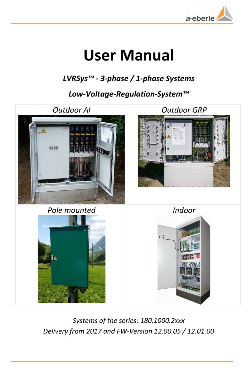
a-eberle Low Voltage Regulation System User manual

Installation manual
LVRSys™ - 3-phase systems
Low Voltage Regulation SystemTM
Outdoor installation Al
Outdoor installation GRP
Pole mount
Indoor installation
Systems of the series: 180.1000.2xxx
Delivered from III/2019


Page 1
Contents
1. User guidance ................................................................................................................ 3
1.1 Target group..............................................................................................................................3
1.2 Warnings ...................................................................................................................................3
1.3 Tips............................................................................................................................................3
1.4 Other symbols...........................................................................................................................4
1.5 Other applicable documents.....................................................................................................4
1.6 Storage ......................................................................................................................................4
2. Scope of delivery/options............................................................................................... 5
3. Packaging....................................................................................................................... 6
3.1 Control cabinet .........................................................................................................................6
3.2 Transformer block.....................................................................................................................7
3.3 Concrete/GRP base ...................................................................................................................7
4. Transport....................................................................................................................... 8
4.1 Transport with pallet.................................................................................................................8
4.1.1 Switch cabinet transport on pallet............................................................................................8
4.1.2 Transformer transport with pallet (only outdoor-systems)......................................................9
4.1.3 Base transport with pallet.........................................................................................................9
4.2 Lifting devices............................................................................................................................9
4.2.1 Use of a crane and the lifting lugs of the Aluminum switch cabinet ........................................9
4.2.2 Switch cabinet GRP ................................................................................................................ 11
4.2.3 Installing the Switch cabinet indoors using a crane and the lifting lugs................................ 12
4.2.4 Pole Mount cabinet with crane lugs ...................................................................................... 13
4.2.5 Lifting the Transformer with a crane using the lifting lugs.................................................... 13
4.2.6 Concrete base ........................................................................................................................ 14
5. Installation....................................................................................................................15
5.1 Fuse protection ...................................................................................................................... 16
5.1.1 Fuse protection for systems with switch-disconnector-fuses ............................................... 16
5.1.2 Fuse protection for systems with NH disconnectors............................................................. 17
5.1.3 Fuse protection for systems with automatic circuit breakers ............................................... 17
5.2 Fuse protection (internal side)............................................................................................... 18
5.3 Systems outdoor installation ................................................................................................. 19
5.3.1 Outdoor installation requirements........................................................................................ 19
5.3.2 Ground hole for concrete base and GRP base....................................................................... 19
5.3.3 Concrete Plinth mounting...................................................................................................... 20
5.3.4 GRP base mounting................................................................................................................ 23

Page 2
We take care of it.
5.3.5 Inserting the transformer block & if applicable, the preliminary stage .................................26
5.3.6 Filling layer around the plinth.................................................................................................27
5.3.7 Mounting the switch cabinets for outdoor installation onto a base......................................27
5.3.8 Locking the switch cabinets - outdoor installations ...............................................................28
5.3.9 Connection of the transformer block to the control unit.......................................................29
5.3.10 Connection of the low voltage cables & grounding................................................................31
5.4 Systems for indoor installation...............................................................................................41
5.4.1 Requirements for indoor installation .....................................................................................41
5.4.2 Base mounting ........................................................................................................................41
5.4.3 Transformers...........................................................................................................................41
5.4.4 Mounting the base LVRSys™indoor installation on the floor ................................................41
5.4.5 Connecting the low-voltage cables.........................................................................................42
5.5 Pole mount Systems ...............................................................................................................46
5.5.1 Mounting the LVRSys™on the pole........................................................................................46
5.5.2 Connecting the low-voltage cables on the grid side...............................................................50
5.6 External installations...............................................................................................................51
6. Commissioning & Decomissioning LVRSys™................................................................... 52
6.1 Lights & Switches ....................................................................................................................52
6.2 Commissioning and decomissioning LVRSys™........................................................................52
6.3 Check that there is no voltage ................................................................................................54
6.4 Current transformer N/PEN-rail..............................................................................................54
6.5 Operation of circuit breakers and switch disconnectors........................................................55
6.5.1 Operation of systems with circuit breakers............................................................................55
6.5.2 Operation of systems with switch disconnectors...................................................................56
6.5.3 Operation of systems with LV fuse-switch-disconnectors......................................................59

Page 3
1. User guidance
The installation manual contains all the important information for installation,
commissioning and operation.
Read the installation manual completely and do not use the product until you have
understood the installation manual.
1.1 Target group
This installation manual is intended for trained specialist personnel as well as trained and
tested operating personnel.
The content of this installation manual must be made accessible to the persons responsible
for the installation and operation of the system.
1.2 Warnings
Structure of the warnings
Warnings are structured as follows:
SIGNAL WORD!
Type and source of danger!
Consequences of non-compliance.
Measures to avoid the danger.
Gradation of the warnings
Warnings differ according to the type of hazard as follows:
DANGER!
Warns of an imminent danger leading to death or serious injury if not
avoided.
WARNING!
Warns of potentially hazardous situation leading to death or serious
injury if not avoided.
CAUTION!
Warns of a potentially hazardous situation leading to moderate or
minor injury if not avoided.
ADVICE!
Warns of potentially hazardous situation that, if not avoided, may
result in damage to property or the environment.
1.3 Tips
Tips for proper use of the device and recommendations.

Page 4
We take care of it.
1.4 Other symbols
Instructions
Structure of the instructions:
Instructions for an action.
Result of action if necessary.
Lists
Structure of unnumbered lists:
0List level 1
–List level 2
Structure of numbered lists:
1) List level 1
2) List level 1
1. List level 2
2. List level 2
1.5 Other applicable documents
For safe and correct use of the system, also observe the additional documents supplied as
well as relevant standards and applicable local regulations.
1.6 Storage
Keep the installation manual, including all applicable documents, in close proximity to the
LVRSys system.

Page 5
2. Scope of delivery/options
The LVRSys systems are built up as a modular system. The main components & documents
are:
0LVRSys™ control unit (for installation in external control cabinets)
0Transformer block
0Control cabinet for outdoor or indoor installation or pole mount
0Base for outdoor installation
0Operating instructions LVRSys™
0Installation manual LVRSys™
0Circuit diagram of the control cabinet LVRSys™
0Test certificate LVRSys™.

Page 6
We take care of it.
3. Packaging
3.1 Control cabinet
The switch cabinet are packed in foil, cardboard or wood (selected order feature), standing
on pallet.
Wood packaging
Figure 3-1 Switch cabinet packed in wood (example)
For special regulations (e.g. export) the packaging may differ.
Figure 3-2 Packaging & shock sticker
To protect the system, the packaging consists of particle board pieces.
Before opening the crate, check the shock sticker
ADVICE!
If the sticker is RED:
Do not remove packaging.
Contact A. Eberle GmbH & Co. KG for further information.

Page 7
3.2 Transformer block
0Outdoor installation
The transformer block is packed in foil, cardboard or wood (selected order feature), lying on
pallet.
3.3 Concrete/GRP base
0Outdoor installation
The base is packed in foil (concrete base), cardboard (GRP-base) or wood (selected order
feature), lying on pallet.

Page 8
We take care of it.
4. Transport
4.1 Transport with pallet
4.1.1 Switch cabinet transport on pallet
With the exception of systems for pole mounting, all switch cabinets must be transported
vertically. Pole mounting systems can also be transported horizontally.
CAUTION!
Avoid damage to the switch cabinet due to incorrect handling
during transport!
Only Transport the switch cabinet upright.
Ensure that the switch cabinet cannot tip over while in transit.
Fasten mounting devices on the board wall.
Figure 4-1 Cabinet transport on truck

Page 9
4.1.2 Transformer transport with pallet (only outdoor-systems)
CAUTION!
Avoid damage to the transformer block due to incorrect handling
during transport!
Transport transformer block in horizontal position only.
Ensure the holding devices are fastened to the tailboard.
4.1.3 Base transport with pallet
No special transport sensitivities.
4.2 Lifting devices
DANGER!
Danger to life if the switch cabinet is dropped during lifting!
Ensure that no body is standing under or nearby to the
suspended load.
CAUTION!
Damage to the system if the control cabinet is dropped!
Always secure the LVRSys™ switch cabinet by the lifting lugs.
Only lift the cabinet vertically (deviation up to a maximum of 60°)
to the lifting lugs.
Ensure the lift upward of the LVRSys™ switch cabinet is done
smoothly without any jerks.
4.2.1 Use of a crane and the lifting lugs of the Aluminum switch cabinet
Transport lugs are located under the weather protection roof.
Removing the weather protection roof:
Loosen the screws at the front (1).
Lift the hood at the front (2).
Push the hood to the back (3).
Lift the hood upward (4).
Installing the weather protection roof:
Lower the hood from above (5).
Push the hood to the front (6).
Fasten the screws at the front (7).

Page 10
We take care of it.
Figure 4-2 Installing and removing the weather protection roof
The screws can be loosened and fastened with a TX 25 screwdriver. The tightening torque
may not exceed 6 Nm.
Use all four transport lugs.
1
2
3
4
5
6
1
2
7

Page 11
Figure 4-3 Transport lugs
4.2.2 Switch cabinet GRP
CAUTION!
Damage to the switch cabinet can occur through incorrect handling
during transit!
Only transport the switch cabinet in an upright position.
Ensure that the switch cabinet cannot tip over.
Ensure fastening of holding devices to the tailboard.
Use mobile crane lugs
Then seal the switch cabinet with blind plugs
Figure 4-4 mobile crane lugs

Page 12
We take care of it.
4.2.3 Installing the Switch cabinet indoors using a crane and the lifting lugs
DANGER!
Danger to life if the switch cabinet is dropped!
Ensure that nobody is standing nearby or under the
suspended load.
Figure 4-5 Lifting eyes distribute the weight being lifted
CAUTION!
Damage to the system will occur if the switch cabinet is dropped !
Always secure the LVRSys™ switch cabinet with all lifting lugs.
Only lift the cabinet up vertically (deviation up to a maximum of
60°) to the lifting lugs.
Lift the LVRSys™ switch cabinet up smoothly avoiding any jerks.
Systems with more than 800 kg can only be lifted vertically –
straight up!
CAUTION!
Damage to the system will occur if the switch cabinet is dropped!
Always move the LVRSys™ switch cabinet smoothly & evenly.

Page 13
4.2.4 Pole Mount cabinet with crane lugs
Two mobile crane lugs are installed on the upper edge of the control cabinet. These are
intended to lift the system.
Abbildung 4-6 mobile crane lugs
4.2.5 Lifting the Transformer with a crane using the lifting lugs
Systems with a preliminary stage and two transformer blocks must be lifted into the ground
base.
DANGER!
Risk of fatal injury if the transformer block is dropped !
Ensure that nobody is standing nearby or under a
suspended load.
CAUTION!
Damage to the system if the transformer block is dropped!
Always secure transformer block using all lifting lugs provided.
Only lift or lower the transformer block in a vertical movement
(deviation up to a maximum of 60°) to the lifting eyes.
Ensure the lifting is done smoothly without any jerks to the
transformer block.

Page 14
We take care of it.
Figure 4-7 Transformer block with four lifting lugs
Use all four lifting lugs.
4.2.6 Concrete base
DANGER!
Risk of fatal injury if the concrete base is dropped or falls over!
Ensure that nobody is standing close-by or under
a suspended load.
There are no special transport considerations.

Page 15
5. Installation
DANGER!
Risk of death due to electric shock!
Only install LVRSys™ in a de-energised state.
CAUTION!
Destruction of components by short-circuit forces!
Use cable clamps in the in- and output of the LVRSys™.
CAUTION!
Destruction of components due to overload!
Only connect the low-voltage grid in BYPASS operation.
(See chapter 6.2)
Sequence for the connection to the low-voltage grid:
Disconnect the low-voltage grid.
Installing the system
Check assembly
Make sure that the system is in Bypass mode
Connect the low-voltage grid.
NOTE!
Aluminum con-
ductor
For direct connection terminals
With aluminum conductors, the oxide layer must be mechanically
removed immediately before contacting and treated with acid- and
alakali-free grease.
The installation location must be kept as free as possible from mois-
ture or aggressive atmosphere.
If an aluminum conductor is used, the screw in the terminal body of
the screw terminal must be tightened to the maximum permissible
tightening torque of the respective terminal block.
If the conductor is connected again, the conductor pretreatment
must be repeated.
For flat connection (also PEN/PE rail)
Aluminum conductors must only be connected to the copper busbar
with specially designed cable lugs (cable lugs with galvanic tinning or
Al-/Cu cable lugs).

Page 16
We take care of it.
5.1 Fuse protection
For protection against short circuits and continuous overcurrents, all systems are equipped
with protective devices in accordance with Table 5-1/Table 5-2. In externally fused systems,
the rated current of the fuses must not exceed the rated currents of the respective
systems.
Only after consultation with the A. Eberle Support Team may larger fuses than specified
be used.
5.1.1 Fuse protection for systems with switch-disconnector-fuses
Protective devices
Coordinated fuse protection 400 V L-L
NH fuse gG NH2
32 A (22 kVA system)
63 A (44 kVA system)
100 A (70 kVA system)
160 A (110 kVA system)
200 A (144 kVA system)
250 A (175 kVA system)
355 A (250 kVA system)
NH fuse gTr NH3
630 A (400 kVA system)
910 A (630 kVA system)
Table 5-1 Fuse protection of the systems at the switch-disconnector-fuse block input (400 V
L-L)
Protective devices
Coordinated fuse protection 230 V L-L
NH fuse gG NH2
32 A (13 kVA system)
63 A (26 kVA system)
100 A (41 kVA system)
160 A (64 kVA system)
200 A (84 kVA system)
250 A (101 kVA system)
355 A (145 kVA system)
NH fuse gG NH3
2 x 500 A (400 kVA system)
Table 5-2 Fuse protection of the systems at the switch-disconnector-fuse block input (230 V
L-L)

Page 17
5.1.2 Fuse protection for systems with NH disconnectors
Protective devices
Coordinated fuse protection 400 V L-L
NH fuse gG NH2
32 A (22 kVA system)
63 A (44 kVA system)
100 A (70 kVA system)
160 A (110 kVA system)
200 A (144 kVA system)
250 A (175 kVA system)
355 A (250 kVA system)
NH fuse gTr NH3
630 A (400 kVA system)
910 A (630 kVA system)
Table 5-3 Fuse protection of the systems at the disconnector block input (400 V L-L)
Protective devices
Coordinated fuse protection 230 V L-L
NH fuse gG NH2
32 A (13 kVA system)
63 A (26 kVA system)
100 A (41 kVA system)
160 A (64 kVA system)
200 A (84 kVA system)
250 A (101 kVA system)
355 A (145 kVA system)
NH fuse gG NH3
2 x 500 A (400 kVA system)
Table 5-4 Fuse protection of the systems at the disconnector block input (230 V L-L)
5.1.3 Fuse protection for systems with automatic circuit breakers
Protective devices
Coordinated fuse protection 400 V L-L
Automatic circuit breaker C
32 A (22 kVA system)
63 A (44 kVA system)
100 A (70 kVA system)
Table 5-5 Fuse protection of the systems at the automatic circuit breaker input (400 V L-L)
Protective devices
Coordinated fuse protection 230 V L-L
Automatic circuit breaker C
32 A (13 kVA system)
63 A (26 kVA system)
100 A (41 kVA system)
Table 5-6 Fuse protection of the systems at the automatic circuit breaker input (230 V L-L)

Page 18
We take care of it.
5.2 Fuse protection (internal side)
System
F8 (3x)
F9 (3x)
Resistors Trafo
big-X2
Resistors
Trafo small-X2
32 A 6 % to
32 A 10 %
D01GG40V16
582.1203
X
MI5HT25V0,63
582.1020.00.63
MI5HT25V0,63
582.1020.00.63
63 A 6 % to
160 A 6 %
D02GG40V25
582.1205
X
MI5HT25V2
582.1020.02
MI5HT25V0,63
582.1020.00.63
160 A 8 % to
160 A 10 %
D02GG40V25
582.1205
X
MI5HT25V5
582.1020.05
MI5HT25V1
582.1020.01
200 A 6 % to
355 A 8 %
D02GG40V40
582.1207
X
MI5HT25V5
582.1020.05
MI5HT25V2
582.1020.02
355 A 10 % to
580 A 8 %
NH00GR50V80
582.1246
D02GG40V25
582.1205
MI5HT25V8
582.1020.08
MI5HT25V5
582.1020.05
580 A 10 % to
910 A 6 %
NH00GR50V100
582.1247
D02GG40V35
582.1206
MI5HT25V8
582.1020.08
MI5HT25V5
582.1020.05
910 A 8 % to
910 A 10 %
NH00GR50V125
D02GG40V50
582.1208
MI6SA12,5V25
MI5HT25V6,3
582.1020.06.30
Table 5-7 Protection of the systems internal side
Measuring voltage taps Output voltage (XF) are protected with G-fuse links super-fast FA
5x20 3.15 A (MI5FA25V3.15 / 582.1018). Measuring Voltages Input voltage (XF) are
protected by G-fuse links super-fast FA 6.3x32 3.15 A (MI6FA25V3.15).
Table of contents
Other a-eberle Controllers manuals
Popular Controllers manuals by other brands
MKS
MKS HPS 947 Series Operation and maintenance manual

Neuralynx
Neuralynx SpectraLynx quick start guide
Atkinson Electronics
Atkinson Electronics PVLC-40MD quick start guide

Evco
Evco EV3 Mix instructions
Unitronics
Unitronics Vision OPLC V130 Replacing

Maguire Products
Maguire Products Weigh Scale Blender WSB Operation & maintenance manual
