manuals.online logo
Brands
  1. Home
  2. •
  3. Brands
  4. •
  5. Danfoss
  6. •
  7. Controllers
  8. •
  9. Danfoss Cascade HFC User guide

Danfoss Cascade HFC User guide

Cascade HC/HFC - CO2system
How to control the system
Application guide
www.danfoss.com/co2
AKS 32 R
AKS 32R
GD/DGS
AKS 11
AKS 2050
AKS 11
AK-PC 740/780
GD/DGS
AKS 11
AKS 32R
AKD 102
AKS 11
DCR
Pump
SGN
AKS 2050
AKS 11
EKC 313
EVR
ETS
DCR
AKD 102
AKD 102
AK-CC 450
AKS 11
AKVH
AK-CC 550 A
AKS 11
AK-PC 740/780
Danfoss
R64-2050.11
AKS 32R
AK-SC 255/
AK-SM 350/
AK-SM 720/
AKA 245
AKS 32R
AKS 11
EVRH
2 Application guide RA8AB102 © Danfoss 10/2010 Cascade HC/HFC - CO2system
Intermediate temperature in a cascade system is
selected based on the required temperature for
high temperature cases in a store which means
they can be cooled by CO2directly. Intermediate
temperature can also be optimised for the high-
est energy efficiency if the system is used for low
temperature only.
Since a cascade system actually consists of two
different refrigeration systems which are inter-
faced but isolated at the cascade heat exchanger,
the design working pressure for each can be
different. CO2design pressure is normally based
on the availability of components and is equal to
40-45 bar (corresponding to +5 - +10°C).
In order to prevent pressure from increasing
above the previously mentioned measurements,
standstill systems are recommended. Safety
valves should have the highest setting. Stand still
pressure can be achieved by raising the desing
pressure to 80-90 bar.
For example:
CO2side
• System design working pressure (saturated suc-
tion temperature): 40 bar (+5°C)
• Safety valve settings: 36 bar (-10% MWP)
• System emergency relief setting: 34 bar (-1°C)
• CO2 discharge pressure setting: 30 bar (-5°C)
The higher the efficiency of the cascade heat
exchanger, the lower the difference between
the condensation temperature of CO2and the
evaporating temperature of the refrigerant on
the high temperature side. As the temperature
difference on the cascade condenser increases,
the overall efficiency of the refrigeration system
decreases!
General description
Temperatures and pressures
in cascade systems
Ammonia/CO2cascade systems have the highest
efficiency of all. If HFC is to be used at a high tem-
perature stage, R134a is a preferable option due
to its thermo dynamical properties and lower
(compared to R404A) GWP potential.
Cascade systems are typical not used in FR ap-
plications with traditional refrigerants. There are a
few reasons for this such as the need to maintain
two different refrigerants in one system; system
control strategy (especially that of a cascade heat
exchanger) is more complex. At the same time
using CO2in cascade systems gives a number of
advantages:
• Eciency of the system is high even in the hot
climates
• Only a small amount of refrigerant is needed for
high temperature stage
• Temperature dierence for cascade heat ex-
changer is relatively low
• On the high side various refrigerants can be
used ex HC/HFC or NH3.
EKC 313
AK-CC 550
AK-CC 450
AK-PC 740/780
AK-PC 740/780
Cascade HC/HFC - CO2system Application guide RA8AB102 © Danfoss 10/2010 3
Temperatures and pressures
in cascade systems (contin-
ued)
On systems with low temperatures of the dis-
charge CO2 gas (low superheat), the superheat
of the expansion valve can be the dimensioning
factor for the heat exchanger.
If a CO2 system has high superheat, then desu-
per-heaters need to be used in order to reduce
the load on the high temperature side.
Optimal intermediate pressure in CO2 cascade
systems depends on a number of parameters
(high temperature refrigerant, load pattern etc.).
Generally 2 cases need to be considered:
Operating sequence of cas-
cade systems
1) Systems with load at the medium temperature.
In this case intermediate pressure should be as
high as possible in order to reduce the load at
the high temperature stage. The limitations are
therefore required temperature on the intermedi-
ate level and pressure rating of the system.
2) Systems without load at medium temperature.
In this case the intermediate temperature should
be in the range of -10 - 0°C (due to the high pres-
sure of the CO2LT) where lower limit is defined
by efficiency and higher by system pressure
rating
In Cascade Systems, it is essential that at least
one compressor in the high temperature side is
running before the first compressor in the low
temperature side can start. Otherwise, the com-
pressor in the low temperature side may be cut
out due to high pressure.
The same sequence is also valid for filling up the
system. First of all, the high temperature circuit
needs to be filled with refrigerant and started up.
When this is done, the CO2can be filled into the
low temperature system.
The high temperature expansion valve (ETS) to
the cascade heat exchanger should begin simul-
taneously with the high temperature compres-
sors. After this, the valve controls the superheat
of the high temperature gas. LT compressors are
then started up by the CO2pressure increase on
the suction line.
Danfoss pack controllers such as AK-PC 740 and
AK-PC 780 are specially designed with built in
control functions to coordinate these operations.
Injection into cascade heat
exchanger
Injecting liquid into a plate heat exchanger is
not a trivial matter. The heat exchanger is often
compact and therefore the time constant is very
low. AKV valves are not recommended for this
application.
It is recommended to use motor valves or other
valves that give constant flow. Desuper-heating
of CO2gas entering the cascade heat exchanger
can also be recommended for three reasons.
One reason is that the gas is often 60°C and
therefore the heat can be rejected to the ambient
or used for heat recovery without problems. The
second reason is to reduce thermal stress in the
heat exchanger. The third reason is that the CO2
gas gives very high heat fluxes which therefore
create unstable conditions on the evaporation
side. Therefore it is recommended to reduce the
superheat on the CO2side.
Distribution on the CO2side is also a critical
issue. This is why the heat exchanger has to be
designed for direct expansion to make sure the
mixture of gas and liquid is evenly distributed to
the heat exchanger.
When the heat exchanger is designed for reason-
able pressure drop at part load, the oil transport
and distribution should work under most condi-
tions.
4 Application guide RA8AB102 © Danfoss 10/2010 Cascade HC/HFC - CO2system
Cascade HFC - CO2system
AKS 32 R
AKS 32R
GD/DGS
AKS 11
AKS 2050
AKS 11
AK-PC 740/780
GD/DGS
AKS 11
AKS 32R
AKD 102
AKS 11
DCR
Pump
SGN
AKS 2050
AKS 11
EKC 313
EVR
ETS
DCR
AKD 102
AKD 102
AK-CC 450
AKS 11
AKVH
AK-CC 550 A
AKS 11
AK-PC 740/780
Danfoss
R64-2050.11
AKS 32R
AK-SC 255/
AK-SM 350/
AK-SM 720/
AKA 245
AKS 32R
AKS 11
EVRH
Cascade HC/HFC - CO2system Application guide RA8AB102 © Danfoss 10/2010 5
Controls of Cascade system Control of cascade systems can be divided into:
• Condenser capacity control
• Compressor capacity control
• Cascade injection control
• MT evaporator CO2 ow control
• LT evaporator injection control
Condenser capacity control Capacity control of the condenser can be ac-
complished via step regulation or speed control
of the fans.
As regulating sensor for the capacity distribu-
tor the condenser pressure should be selected.
The reference for the regulation can be defined
in two ways. Either as a xed reference or as a
reference that varies according to the outdoor
temperature. The reference for the condensing
pressure is set in °C (°F).
Compressor capacity
controls
Pack controller AK-PC 740 (up to 4 compressors)
or AK-PC 780 (up to 8 compressors) controls the
LT suction pressure and is a standard controller
for controlling one suction group in any refrigera-
tion system. The controller is capable of regulat-
ing variable speed of two compressors combined
with one-step compressors of the same or differ-
ent sizes, depending on the choice of coupling
pattern.
A unique feature in the AK-PC 740/780 make it
possible to use the Pc pressure in the LT CO2side
as control sensor for the HT suction pressure. This
to ensure fast and stable control of the condens-
ing pressure of LT CO2side.
Low-pressure /
high-pressure coordination
The AK-PC 740/780 is also able to coordinate the
LT and HT start to ensure a smooth operation.
Here the high-pressure compressors can start
either as a result of:
- Load on the high-pressure circuit
- Requirements from the low-pressure circuit
The high-pressure circuit will still ensure that the
low-pressure circuit is only permitted to start
when at least one high-pressure compressor has
started. It will also ensure that security timers and
compressor timers are complied with.
Oil Management /
Oil equalisation
The build in oil management system covers most
systems found on the market to day. Can be used
with CO2as well as all other conventional refrig-
erants and support input signals from :
• Level switch on compressor
• Level switch on oil separator
• Level switch on oil receiver
• Pressure transmitter on oil receiver
Oil supply to the compressors is managed by
activating solenoid valves with user defined ON/
Off pulse sequences.
HT comp. release
output
LT comp. release.
input
HT comp. request
input
LT comp. request
output
Here both a relay output and an On/off input are used on both control-
lers.
Cap. reqquest
Cap.release
6 Application guide RA8AB102 © Danfoss 10/2010 Cascade HC/HFC - CO2system
Cascade injection control In systems with cascade regulating and CO2
as refrigerant on the low temperature circuit
EKC 313 can regulate liquid injection (by means
of an ETS stepper expansion valve) into the cas-
cade heat exchanger in one of two ways:
• Optimize superheat
• Regulate the condensation pressure at the low
temperature circuit while ensuring that the
superheat does not become too low.
If there are no evaporators on the high tempera-
ture circuit the cascade controller should be set
in control mode 1 to optimise superheat. In this
application the condensation pressure on the low
temperature circuit should be controlled by the
compressor capacity controller in the high tem-
perature circuit. Here the LT PC signal is received
at the HT P0 input.
MT evaporator CO2flow
control
The air temperature in the medium temperature
display cases or rooms is controlled by opening/
closing a solenoid valve/motor valve in the CO2
supply to the evaporator. The actual temperature
control can take place in two ways: as ordinary
ON/OFF regulation with a differential, or as
modulating control (PWM) where the tempera-
ture variation will not be nearly as big as in ON/
OFF control.
In a system with several evaporators supplied by
the same CO2liquid pump, modulating tem-
perature control should be chosen as this also
provides a more constant flow of CO2to the CO2
pump.
LT evaporator injection
control
Injection control for the low temperature case
and cold room evaporators is an AK-CC 550A
utilizing pulse-width-modulating injection valves
AKVH and patented adaptive software algorithms
to optimise system performance and operation.
Period time, n63
Pressure control The Danfoss CO2controllers have more pressure
safety functions which prevents safety valves to
open and hereby loss of charge.
AK PC 740 pack controller
A max compressor discharge pressure safety
function will reduce compressor capacity
Cascade HC/HFC - CO2system Application guide RA8AB102 © Danfoss 10/2010 7
• 4 compressors with up to 3 un-loaders
• 6 fans
• Max. 60 inputs/outputs
• Variable speed control on lead compressor and
condenser fans
• Build in oil Management functions
• Release-request function for coordination between
high-pressure and low-pressure compressors.
• 8 compressors with up to 3 un-loaders
• 8 fans.
• Max. 100 inputs/outputs.
• For cooling with brine or pumped CO2
• For use with a thermostatic expansion valve.
• Energy optimisation of the whole refrigeration
appliance
• One controller for several dierent refrigeration
appliances
• Natural, electric or hot gas defrost
• For cooling with Electronic expansion valve
• Adaptive control of superheat
• Adaptive defrosting based on evaporator perform-
ance
• Stepper motor driver for ETS or CCM expansion
valve.
• 0 - 10 V output for ICMTS valves
• Electrically operated expansion valves for precise
liquid injection in evaporators
• Fully balanced, providing bi-ow feature as well as
solenoid tight shut-off function in both flow direc-
tions.
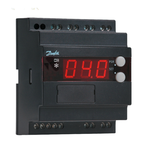
AK-PC 740
Flexible controller for capacity control of
compressors and condenser fans. Number of
I/O can be extended with AK-XM extension
modules.
AK-PC 780
As AK-PC 740 plus:
AK-CC 450
Complete refrigeration appliance control with
great flexibility to adapt to all types of refrigera-
tion appliances and cold storage rooms.
AK-CC 550A
As AK-CC 450 +
AK-CC 750
Flexible refrigeration appliance controller for
control of up to 4 evaporators.
EKC 313
Controller for liquid injection in cascade heat
exchangers with CO2as refrigerant on the low
temperature circuit.
ETS
ETS is a series of electrically operated (stepper
motor) expansion valve
8 Application guide RA8AB102 © Danfoss 10/2010 Cascade HC/HFC - CO2system
FC-SPMC
Danfoss can accept no responsibility for possible errors in catalogues, brochures and other printed material. Danfoss reserves the right to alter its products without notice. This also applies to products
already on order provided that such alternations can be made without subsequential changes being necessary in specifications already agreed.
All trademarks in this material are property of the respecitve companies. Danfoss and Danfoss logotype are trademarks of Danfoss A/S. All rights reserved.

This manual suits for next models

1

Other Danfoss Controllers manuals

Danfoss PVED-CLS User manual

Danfoss

Danfoss PVED-CLS User manual

Danfoss ADAP-KOOL AK-PC 781 Guide

Danfoss

Danfoss ADAP-KOOL AK-PC 781 Guide

Danfoss AFP Series User manual

Danfoss

Danfoss AFP Series User manual

Danfoss FH-TC User manual

Danfoss

Danfoss FH-TC User manual

Danfoss EKC 326A User manual

Danfoss

Danfoss EKC 326A User manual

Danfoss ECL Comfort 310 User manual

Danfoss

Danfoss ECL Comfort 310 User manual

Danfoss MCV105C User manual

Danfoss

Danfoss MCV105C User manual

Danfoss 087H3803 User manual

Danfoss

Danfoss 087H3803 User manual

Danfoss Optyma Plus User manual

Danfoss

Danfoss Optyma Plus User manual

Danfoss MCI 50-3 I-O User manual

Danfoss

Danfoss MCI 50-3 I-O User manual

Danfoss ACI 30-1 User manual

Danfoss

Danfoss ACI 30-1 User manual

Danfoss EKC 331 User manual

Danfoss

Danfoss EKC 331 User manual

Danfoss VLT MCD 600 User manual

Danfoss

Danfoss VLT MCD 600 User manual

Danfoss EKE 347 User manual

Danfoss

Danfoss EKE 347 User manual

Danfoss AK-PC 420 User manual

Danfoss

Danfoss AK-PC 420 User manual

Danfoss EKC 102B User manual

Danfoss

Danfoss EKC 102B User manual

Danfoss AME 655 User manual

Danfoss

Danfoss AME 655 User manual

Danfoss VLT DMS 300 User manual

Danfoss

Danfoss VLT DMS 300 User manual

Danfoss ECL Comfort C31 User manual

Danfoss

Danfoss ECL Comfort C31 User manual

Danfoss OPTYMA Plus OP-LPQM User manual

Danfoss

Danfoss OPTYMA Plus OP-LPQM User manual

Danfoss 101N0715 User manual

Danfoss

Danfoss 101N0715 User manual

Danfoss vlt soft starter mcd 500 User manual

Danfoss

Danfoss vlt soft starter mcd 500 User manual

Danfoss AK-PC 572 User manual

Danfoss

Danfoss AK-PC 572 User manual

Danfoss EKE 1A User manual

Danfoss

Danfoss EKE 1A User manual

Popular Controllers manuals by other brands

Woodward TecJet 110 Installation and operation manual

Woodward

Woodward TecJet 110 Installation and operation manual

Schischek ExMax quick start guide

Schischek

Schischek ExMax quick start guide

YASKAWA DS031 installation instructions

YASKAWA

YASKAWA DS031 installation instructions

Wibre 5.0635.09.52 installation manual

Wibre

Wibre 5.0635.09.52 installation manual

Mitsubishi Electric Central Controller G-50A Technical manual

Mitsubishi Electric

Mitsubishi Electric Central Controller G-50A Technical manual

Ponpe 595 Series manual

Ponpe

Ponpe 595 Series manual

HomeMatic HM-LC-Dim1T-FM Installation and operating manual

HomeMatic

HomeMatic HM-LC-Dim1T-FM Installation and operating manual

Alcad 912-MS Series Installation and programming manual

Alcad

Alcad 912-MS Series Installation and programming manual

Nico Technology 3010L user manual

Nico Technology

Nico Technology 3010L user manual

Eliwell ICPlus 915 manual

Eliwell

Eliwell ICPlus 915 manual

artisan DMC-41-3 Series user manual

artisan

artisan DMC-41-3 Series user manual

ESD electronic CAN-CBX-CPU5202 Hardware manual

ESD electronic

ESD electronic CAN-CBX-CPU5202 Hardware manual

Woodward EGB-10 Operation manual

Woodward

Woodward EGB-10 Operation manual

Graco G Series Instructions-parts list

Graco

Graco G Series Instructions-parts list

Honeywell SEC-H-600 installation instructions

Honeywell

Honeywell SEC-H-600 installation instructions

Continental Access uniVerse CICP2100 Quick setup guide

Continental Access

Continental Access uniVerse CICP2100 Quick setup guide

Emerson Baumann 24000CVF instruction manual

Emerson

Emerson Baumann 24000CVF instruction manual

Toa DP-L2 operating instructions

Toa

Toa DP-L2 operating instructions

manuals.online logo
manuals.online logoBrands
  • About & Mission
  • Contact us
  • Privacy Policy
  • Terms and Conditions

Copyright 2025 Manuals.Online. All Rights Reserved.