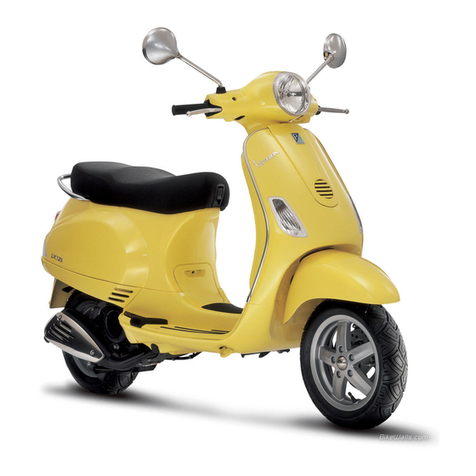
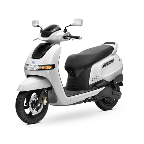
A-EON 350cc User manual

GENERAL INFORMATION
1-1
2010 URBAN 350 EFI
SERVICE MANUAL
FOREWORD
This service manual is designed primarily for use by certified Aeon Master Service
Dealer technicians in a properly equipped shop and should be kept available for
reference. All references to left and right side of the vehicle are from the operator's
perspective when seated in a normal riding position.
Some procedures outlined in this manual require a sound knowledge of mechanical
theory tool use and shop procedures in order to perform the work safely and
correctly. Technicians should read the text and be familiar with service procedures
before starting the work. Certain procedures require the use of special tools. Use
only the proper tools as specified.

GENERAL INFORMATION
1-2
UNDERSTANDING MANUAL SAFETY LABELS AND DIRECTIONS
Throughout this manual, important information is brought to your attention by the following symbols:
SAFETY ALE T WA NING indicates a potential hazard that may result in severe injury or death to the operator, bystander
or person(s) inspecting or servicing the vehicle.
SAFETY ALE T CAUTION indicates a potential hazard that may result in minor personal injury or damage to the vehicle.
CAUTION indicates special precautions that must be taken to avoid vehicle damage or property damage.
NOTE:
NOTE provides key information by clarifying instructions.
IMPORTANT:
IMPO TANT provides key reminders during disassembly, assembly and inspection of components.

GENERAL INFORMATION
1-3
1
GENERAL INFORMATION
1
MAINTENANCE
2
CVT
3
ENGINE / TRANSMISSION
4
ELECTRONIC FUEL INJECTION
5
BODY FRAME
6
ELECTRICAL
7
2
3
4

GENERAL INFORMATION
1-4
CHAPTER 1
MODEL INFORMATION . . . . . . . . . . . . . . . . . . . . . . . . . . . . . . . . . . . . . . . . . . . . . . . . . . . . . . . . . . . . . . . .1-2
VIN IDENTIFICATION . . . . . . . . . . . . . . . . . . . . . . . . . . . . . . . . . . . . . . . . . . . . . . . . . . . . . . . . . . . . . . . . . . . . . . . . . . . . . . . . .1-2
ENGINE SERIAL NUMBER LOCATION . . . . . . . . . . . . . . . . . . . . . . . . . . . . . . . . . . . . . . . . . . . . . . . . . . . . . . . . . . . . . . . . . . .1-2
VEHICLE IDENTIFICATION NUMBER LOCATION . . . . . . . . . . . . . . . . . . . . . . . . . . . . . . . . . . . . . . . . . . . . . . . . . . . . . . . .1-2
GENERAL SPECIFICATIONS . . . . . . . . . . . . . . . . . . . . . . . . . . . . . . . . . . . . . . . . . . . . . . . . . . . . . . . . . . .1-3
URBAN 350I . . . . . . . . . . . . . . . . . . . . . . . . . . . . . . . . . . . . . . . . . . . . . . . . . . . . . . . . . . . . . . . . . . . . . . . . . . . . . . . . . . . . . . .1-3
SPECIFICATION UEBAN 350I . . . . . . . . . . . . . . . . . . . . . . . . . . . . . . . . . . . . . . . . . . . . . . . . . . . . . . . . . . . . . . . . . . . . . . . . .1-4
CONVERSION TABLE . . . . . . . . . . . . . . . . . . . . . . . . . . . . . . . . . . . . . . . . . . . . . . . . . . . . . . . . . . . . . . . . . . . . . . . . . . . . . . . . .1-5
GLOSSARY OF TERMS . . . . . . . . . . . . . . . . . . . . . . . . . . . . . . . . . . . . . . . . . . . . . . . . . . . . . . . . . . . . . . . . . . . . . . . . . . .1-6

GENERAL INFORMATION
1-5
MODEL INFORMATION
VIN IDENTIFICATION
The frame can be found under foot pedal stamped on the right
side of frame.
The vehicle identification number (VIN) and engine serial
number are important for identification purposes. See the
illustrations.
VEHICLE IDENTIFICATION NUMBER
LOCATION
ENGINE SERIAL NUMBER LOCATION
Engine serial number local under rear seat stamped on the
front of crankcase beneath passenger foot pedal.

GENERAL INFORMATION
1-6
GENERAL SPECIFICATION
URBAN 350 I
Model---AS31-62E
Model number---RF3SA3110AT????????
Engine Model---T62N

GENERAL INFORMATION
1-7
SPECIFICATIONS
MODEL: URNAN 350i
ENGINE DRIVE SYSTEM
Type
4 Stroke, Single horizontal camshaft
ear Box Oil capacity
200 CC
Displacement
313 CC ear Oil type 80w90
Cooling Liquid cooled Clutch type Dry Centrifugal clutch
Bore and stroke
78 mm *65.6 mm Final drive ratio 40/12*38/13=9.74
Compression ratio
10.4 : 1
Number of valve 2 ocker arm activated
Inlet valve Ø
ØØ
Ø Ø 33.50mm
Inlet valve clearance 0.10mm
CHASSIS
Exhaust valve Ø
ØØ
Ø Ø 30.00mm Frame Steel
Exhaust valve clearance
0.12mm Front suspension
Telescope forks
ubrication Wet sump and pump pressurized Front wheel travel
100mm
Recommended oil 0W/ 40 Rear suspension
Swing Arm
Oil capacity 1800 CC Rear wheel travel
135 mm
Starting system Electric start/ DC, CDI Front brake
Duel disc with single bore caliper
Max. Power
16.5kw/7500rpm Rear brake
Single Disc with single bore caliper
Max. Torque
25Nm/ 4000rpm Front tire
120/70-16, 29psi
FUEL SYSTEM
Rear tire
140/70-15, 36psi
Type Electrical Fuel Injection
Fuel Delivery Electronic Fuel Pump
Fuel Pressure 3 Bar/ 43.5psi
DIMENSIONS
Throttle dimensions 30mm Overall length
2175 mm
Fuel Capacity 13.5 Liter Overall width
840 mm
Idle RPM 1500±100 Overall height
1290 mm
Seat height
800mm
Wheelbase
1545mm
ENG. ELECTRICAL
Max. Permissible weight
200Kg
Charging system Alternator and voltage regulator Number of passenger
2
Alternator output 168W@4000 PM Min. ground clearance
160mm
Ignition type TDI Dry weight
175Kg
Spark plug type NGK/ DP 7EA-9 Fuel tank capacity
13.5 Liter
Spark plug gap 0.6~0.7mm Max. Speed
120 km/hr
RPM limiter setting 8500 rpm
Battery type GTX10-BS
Fuse type Charge 30A/ Main 15A/ Light
10A/ Spare 15A

GENERAL INFORMATION
1-8
CONVERSION TABLE
Unit of Measure
Multiplied by
Converts to
ft. lbs. x 12 = in. lbs.
in. lbs. x .0833 = ft. lbs.
ft. lbs. x 1.356 = Nm
in. lbs x .0115
= kg-m
Nm x .7376 = ft. lbs.
kg-m x 7.233 = ft. lbs.
kg-m x 86.796 = in. lbs.
kg-m x 10 = Nm
in. x 25.4 = mm
Mm x .03937 = in.
in. x 2.54 = cm
mile (mi.) x 1.6 = km
Km x .6214 = mile (mi.)
Ounces (oz.) x 28.35 = Grams (g)
Fluid Ounces (fl. oz.) x 29.57 = Cubic Centimeters (cc)
Cubic Centimeters (cc) x .03381 = Fluid Ounces (fl. oz.)
Grams (g) x 0.035 = Ounces (oz.)
lb. x .454 = kg
kg x 2.2046 = lb.
Cubic inches (cu. in) x 16.387 = Cubic centimeters (cc)
Cubic centimeters (cc) x 0.061 = Cubic inches (cu. in)
Imperial pints (Imp pt.) x 0.568 = Liters (l)
Liters (l) x 1.76 = Imperial pints (Imp pt.)
Imperial quarts (Imp qt.) x 1.137 = Liters (l)
Liters (l) x 0.88 = Imperial quarts (Imp qt.)
Imperial quarts (Imp qt.) x 1.201 = US quarts (US qt.)
US quarts (US qt.) x 0.833 = Imperial quarts (Imp qt.)
US quarts (US qt.) x 0.946 = Liters (l)
Liters (l) x 1.057 = US quarts (US qt.)
US gallons (US gal) x 3.785 = Liters (l)
Liters (l) x 0.264 = US gallons (US gal)
Pounds - force per square inch x 6.895 = Kilopascals (kPa)
Kilopascals (kPa) x 0.145 = Pounds - force per square inch (psi)
Kilopascals (kPa) x 0.01 = Kilograms - force per square cm
Kilograms - force per square x 98.1 = Kilopascals (kPa)
P (3.14)xR2x H (height)
= Cylinder Volume
°C to °F:
9/5
(°C + 32) = °F
°F to °C:
5/9
(°F - 32) = °C

GENERAL INFORMATION
1-9
GLOSSARY OF TERMS
ABDC: After bottom dead center.
ACV: Alternating current voltage.
Alternator: Electrical generator producing voltage alternating current.
ATDC: After top dead center.
BBDC: Before bottom dead center.
BDC: Bottom dead center.
BTDC: Before top dead center.
CC: Cubic centimeters.
Center Distance: istance between center of crankshaft and center of driven clutch shaft.
Chain Pitch: istance between chain link pins (No. 35 = 3/8" or 1 cm). Polaris measures chain length in number of pitches.
CI: Cubic inches.
Clutch Buttons: Plastic bushings which aid rotation of the movable sheave in the drive and driven clutch.
Clutch Offset: rive and driven clutches are offset so that drive belt will stay nearly straight as it moves along the clutch face.
Clutch Weights: Three levers in the drive clutch which relative to their weight, profile and engine RPM cause the drive clutch to close and
grip the drive belt.
Crankshaft Run-Out: Run-out or "bend" of crankshaft measured with a dial indicator while crankshaft is supported between centers on V
blocks or resting in crankcase. Measure at various points especially at PTO.
CVT: Centrifugal Variable Transmission ( rive Clutch System)
DCV: irect current voltage.
Dial Bore auge: A cylinder-measuring instrument, which uses a dial indicator. Good for showing taper and out-of-round in the cylinder
bore.
Electrical Open: Open circuit. An electrical circuit which isn't complete.
Electrical Short: Short circuit. An electrical circuit that is completed before the current reaches the intended load. (i.e. a bare wire touching
the chassis).
End Seals: Rubber seals at each end of the crankshaft.
Engagement RPM: Engine RPM at which the drive clutch engages to make contact with the drive belt.
ft.: Foot/feet.
Foot Pound: Ft. lb. A force of one pound at the end of a lever one foot in length, applied in a rotational direction.
g: Gram. Unit of weight in the metric system.
gal.: Gallon.
ID: Inside diameter.
in.: Inch/inches.
Inch Pound: In. lb. 12 in. lbs. = 1 ft. lb.
kg/cm2: Kilograms per square centimeter.
kg-m: Kilogram meters.
Kilogram/meter: A force of one kilogram at the end of a lever one meter in length, applied in a rotational direction.
l or ltr: Liter.
lbs/in2: Pounds per square inch.
Left or Right Side: Always referred to based on normal operating position of the driver.
m: Meter/meters.
Mag: Magneto.
Magnetic Induction: As a conductor (coil) is moved through a magnetic field, a voltage will be generated in the windings. Mechanical
energy is converted to electrical energy in the stator.
mi.: Mile/miles.

GENERAL INFORMATION
1-10
mm: Millimeter. Unit of length in the metric system. 1 mm = approximately .040".
Nm: Newton meters.
OD: Outside diameter.
Ohm: The unit of electrical resistance opposing current flow.
oz.: Ounce/ounces.
Piston Clearance: Total distance between piston and cylinder wall.
psi.: Pounds per square inch.
PTO: Power take off.
qt.: Quart/quarts.
Regulator: Voltage regulator. Regulates battery charging system output at approx. 14.5 CV as engine RPM increases.
Reservoir Tank: The fill tank in the liquid cooling system.
Resistance: In the mechanical sense, friction or load. In the electrical sense, ohms, resulting in energy conversion to heat.
RPM: Revolutions per minute.
Seized Piston: Galling of the sides of a piston. Usually there is a transfer of aluminum from the piston onto the cylinder wall.
Possible causes: 1) improper lubrication; 2) excessive temperatures; 3) insufficient piston clearance; 4) stuck piston rings.
Stator Plate: The plate mounted under the flywheel supporting the battery charging coils.
TDC: Top dead center. Piston's most outward travel from crankshaft.
Volt: The unit of measure for electrical pressure of electromotive force. Measured by a voltmeter in parallel with the circuit.
Watt: Unit of electrical power. Watts = amperes x volts.
WOT: Wide open throttle.

GENERAL INFORMATION
1-11

MAINTENANCE
2-12
CHAPTER 2
PERIODIC MAINTENANCE CHART . . . . . . . . . . . . . . . . . . . . . . . . . . . . . . . . . . . . . . . . . . . . . . . . . . . . . .2-3
PERIODIC MAINTENANCE OVERVIEW . . . . . . . . . . . . . . . . . . . . . . . . . . . . . . . . . . . . . . . . . . . . . . . . . . . . . . . . . . . . . . . .2-3
SEVERE USE DEFINITION . . . . . . . . . . . . . . . . . . . . . . . . . . . . . . . . . . . . . . . . . . . . . . . . . . . . . . . . . . . . . . . . . . . . . . . . . . . .2-3
MANTENANCE CHART EY . . . . . . . . . . . . . . . . . . . . . . . . . . . . . . . . . . . . . . . . . . . . . . . . . . . . . . . . . . . . . . . . . . . . . . . . . . .2-3
MAINTENANCE INTERVAL . . . . . . . . . . . . . . . . . . . . . . . . . . . . . . . . . . . . . . . . . . . . . . . . . . . . . . . . . . . . . . . . . . . . . . . . . . .2-4
GENERAL VEHICLE INSPECTION AND MAINTENANCE . . . . . . . . . . . . . . . . . . . . . . . . . . . . . . . . . . . .2-5
FRAME, NUTS, BOLTS AND FASTENER INSPECTION . . . . . . . . . . . . . . . . . . . . . . . . . . . . . . . . . . . . . . . . . . . . . . . . . . . . .2-5
STANDARD TORQUE SPECIFICATIONS . . . . . . . . . . . . . . . . . . . . . . . . . . . . . . . . . . . . . . . . . . . . . . . . . . . . . . . . . . . . . . . .2-5
STANDARD FASTENER TORQUES . . . . . . . . . . . . . . . . . . . . . . . . . . . . . . . . . . . . . . . . . . . . . . . . . . . . . . . . . . . . . . . . . . . .2-5
MAINTENANCE QUIC REFERENCE . . . . . . . . . . . . . . . . . . . . . . . . . . . . . . . . . . . . . . . . . . . . . . . . . . . . . . . . . . . . . . . . . . . .2-5
PREPARATION FOR REMOVAL PROCEDURES . . . . . . . . . . . . . . . . . . . . . . . . . . . . . . . . . . . . . . . . . . . . . . . . . . . . . . . . .2-6
REPLACEMENT PARTS . . . . . . . . . . . . . . . . . . . . . . . . . . . . . . . . . . . . . . . . . . . . . . . . . . . . . . . . . . . . . . . . . . . . . . . . . . . . . .2-6
GAS ETS, OIL SEALS AND O-RING . . . . . . . . . . . . . . . . . . . . . . . . . . . . . . . . . . . . . . . . . . . . . . . . . . . . . . . . . . . . . . . . . . . .2-6
FUEL AND INTAKE SYSTEM . . . . . . . . . . . . . . . . . . . . . . . . . . . . . . . . . . . . . . . . . . . . . . . . . . . . . . . . . . .2-6
FUEL SYSTEM . . . . . . . . . . . . . . . . . . . . . . . . . . . . . . . . . . . . . . . . . . . . . . . . . . . . . . . . . . . . . . . . . . . . . . . . . . . . . . . . . . . . .2-6
FUEL LINES . . . . . . . . . . . . . . . . . . . . . . . . . . . . . . . . . . . . . . . . . . . . . . . . . . . . . . . . . . . . . . . . . . . . . . . . . . . . . . . . . . . . . . . . .2-6
FUEL PUMP/ FUEL FILTERS/ PUMP REGULATOR . . . . . . . . . . . . . . . . . . . . . . . . . . . . . . . . . . . . . . . . . . . . . . . . . . . . . . . . .2-7
VENT LINE . . . . . . . . . . . . . . . . . . . . . . . . . . . . . . . . . . . . . . . . . . . . . . . . . . . . . . . . . . . . . . . . . . . . . . . . . . . . . . . . . . . . . . . . .2-7
THROTTLE INSPECTION . . . . . . . . . . . . . . . . . . . . . . . . . . . . . . . . . . . . . . . . . . . . . . . . . . . . . . . . . . . . . . . . . . . . . . . . . . . . .2-7
THROTTLE FREEPLAY ADJUSTMENT . . . . . . . . . . . . . . . . . . . . . . . . . . . . . . . . . . . . . . . . . . . . . . . . . . . . . . . . . . . . . . . .2-7
AIR CLEANER SERVICE . . . . . . . . . . . . . . . . . . . . . . . . . . . . . . . . . . . . . . . . . . . . . . . . . . . . . . . . . . . . . . . . . . . . . . . . . . . . . .2-8
ENGINE . . . . . . . . . . . . . . . . . . . . . . . . . . . . . . . . . . . . . . . . . . . . . . . . . . . . . . . . . . . . . . . . . . . . . . . . . . . . .2-8
ENGINE OIL LEVEL . . . . . . . . . . . . . . . . . . . . . . . . . . . . . . . . . . . . . . . . . . . . . . . . . . . . . . . . . . . . . . . . . . . . . . . . . . . . . . . . . .2-8
ENGINE OIL AND FILTER SERVICE . . . . . . . . . . . . . . . . . . . . . . . . . . . . . . . . . . . . . . . . . . . . . . . . . . . . . . . . . . . . . . . . . . . .2-9
ENGINE BREATHER HOSE INSPECTION . . . . . . . . . . . . . . . . . . . . . . . . . . . . . . . . . . . . . . . . . . . . . . . . . . . . . . . . . . . . . . . .2-9
ENGINE MOUNT LOCATION . . . . . . . . . . . . . . . . . . . . . . . . . . . . . . . . . . . . . . . . . . . . . . . . . . . . . . . . . . . . . . . . . . . . . . . . . .2-10
TRANSMISSION CASE . . . . . . . . . . . . . . . . . . . . . . . . . . . . . . . . . . . . . . . . . . . . . . . . . . . . . . . . . . . . . . .2-10
TRANSMISSION LUBRICATION . . . . . . . . . . . . . . . . . . . . . . . . . . . . . . . . . . . . . . . . . . . . . . . . . . . . . . . . . . . . . . . . . . . . . . .2-10
TRANSMISSION LUBRICANT CHANGE . . . . . . . . . . . . . . . . . . . . . . . . . . . . . . . . . . . . . . . . . . . . . . . . . . . . . . . . . . . . . . . .2-10
COOLING SYSTEM . . . . . . . . . . . . . . . . . . . . . . . . . . . . . . . . . . . . . . . . . . . . . . . . . . . . . . . . . . . . . . . . . . 2-11
COOLING SYSTEM OVERVIEW . . . . . . . . . . . . . . . . . . . . . . . . . . . . . . . . . . . . . . . . . . . . . . . . . . . . . . . . . . . . . . . . . . . . . . .2-11
COOLANT LEVER INSPECTION . . . . . . . . . . . . . . . . . . . . . . . . . . . . . . . . . . . . . . . . . . . . . . . . . . . . . . . . . . . . . . . . . . . . . . .2-11
COOLANT STRENGTH/ TYPE . . . . . . . . . . . . . . . . . . . . . . . . . . . . . . . . . . . . . . . . . . . . . . . . . . . . . . . . . . . . . . . . . . . . . . . . .2-12
COOLANT SYSTEM HOSE . . . . . . . . . . . . . . . . . . . . . . . . . . . . . . . . . . . . . . . . . . . . . . . . . . . . . . . . . . . . . . . . . . . . . . . . . . . .2-12
RADIATOR . . . . . . . . . . . . . . . . . . . . . . . . . . . . . . . . . . . . . . . . . . . . . . . . . . . . . . . . . . . . . . . . . . . . . . . . . . . . . . . . . . . . . . . . .2-12
COOLANT DRAIN . . . . . . . . . . . . . . . . . . . . . . . . . . . . . . . . . . . . . . . . . . . . . . . . . . . . . . . . . . . . . . . . . . . . . . . . . . . . . . . . . . . .2-12

MAINTENANCE
2-13
WHEELS AND TIRES . . . . . . . . . . . . . . . . . . . . . . . . . . . . . . . . . . . . . . . . . . . . . . . . . . . . . . . . . . . . . . . . .2-13
TIRE PRESSURE MEASUREMENT . . . . . . . . . . . . . . . . . . . . . . . . . . . . . . . . . . . . . . . . . . . . . . . . . . . . . . . . . . . . . . . . . . . .2-13
WEAR INDICATOR . . . . . . . . . . . . . . . . . . . . . . . . . . . . . . . . . . . . . . . . . . . . . . . . . . . . . . . . . . . . . . . . . . . . . . . . . . . . . . . . . .2-13
CHEC WHEELS . . . . . . . . . . . . . . . . . . . . . . . . . . . . . . . . . . . . . . . . . . . . . . . . . . . . . . . . . . . . . . . . . . . . . . . . . . . . . . . . . .2-14
ELECTRICAL AND IGNITION SYSTEM . . . . . . . . . . . . . . . . . . . . . . . . . . . . . . . . . . . . . . . . . . . . . . . . . 2-1
BATTERY MAINTENANCE . . . . . . . . . . . . . . . . . . . . . . . . . . . . . . . . . . . . . . . . . . . . . . . . . . . . . . . . . . . . . . . . . . . . . . . . . . .2-14
BATTERY REMOVAL . . . . . . . . . . . . . . . . . . . . . . . . . . . . . . . . . . . . . . . . . . . . . . . . . . . . . . . . . . . . . . . . . . . . . . . . . . . . . .2-15
BATTERY INSTALLATION . . . . . . . . . . . . . . . . . . . . . . . . . . . . . . . . . . . . . . . . . . . . . . . . . . . . . . . . . . . . . . . . . . . . . . . . . . .2-15
BATTERY OFF SEASON STORAGE . . . . . . . . . . . . . . . . . . . . . . . . . . . . . . . . . . . . . . . . . . . . . . . . . . . . . . . . . . . . . . . . . . . .2-15
SPAR PLUG SERVICE . . . . . . . . . . . . . . . . . . . . . . . . . . . . . . . . . . . . . . . . . . . . . . . . . . . . . . . . . . . . . . . . . . . . . . . . . . .2-16
STEERING AND SUSPENSION . . . . . . . . . . . . . . . . . . . . . . . . . . . . . . . . . . . . . . . . . . . . . . . . . . . . . . . . 2-16
STEERING AND SUSPENSION . . . . . . . . . . . . . . . . . . . . . . . . . . . . . . . . . . . . . . . . . . . . . . . . . . . . . . . . . . . . . . . . . . . . . . .2-16
HANDLEBAR INSPECTION . . . . . . . . . . . . . . . . . . . . . . . . . . . . . . . . . . . . . . . . . . . . . . . . . . . . . . . . . . . . . . . . . . . . . . . . . . .2-16
STEERING HEAD INSPECTION . . . . . . . . . . . . . . . . . . . . . . . . . . . . . . . . . . . . . . . . . . . . . . . . . . . . . . . . . . . . . . . . . . . . . . .2-16
FRONT FOR . . . . . . . . . . . . . . . . . . . . . . . . . . . . . . . . . . . . . . . . . . . . . . . . . . . . . . . . . . . . . . . . . . . . . . . . . . . . . . . . . . . . .2-17
REAR SHOC PRELOAD ADJUSTMENT . . . . . . . . . . . . . . . . . . . . . . . . . . . . . . . . . . . . . . . . . . . . . . . . . . . . . . . . . . . . . . . .2-17
BRAKE SYSTEM . . . . . . . . . . . . . . . . . . . . . . . . . . . . . . . . . . . . . . . . . . . . . . . . . . . . . . . . . . . . . . . . . . . . .2-18
BRA E FLUID INSPECTION . . . . . . . . . . . . . . . . . . . . . . . . . . . . . . . . . . . . . . . . . . . . . . . . . . . . . . . . . . . . . . . . . . . . . . . . . . .2-18
BRA E PAD/ DISC INSPECTION . . . . . . . . . . . . . . . . . . . . . . . . . . . . . . . . . . . . . . . . . . . . . . . . . . . . . . . . . . . . . . . . . . . .2-18
BRA E HOSE AND FITTING INSPECTION . . . . . . . . . . . . . . . . . . . . . . . . . . . . . . . . . . . . . . . . . . . . . . . . . . . . . . . . . . . .2-18

MAINTENANCE
2-14
PERIODIC MAINTENANCE CHART
PERIODIC MAINTENANCE OVERVIEW
Careful periodic maintenance will help keep your vehicle in the safest, most reliable condition. Inspection, adjustment and
lubrication of important components are explained in the periodic maintenance chart.
Inspect, clean, lubricate, adjust and replace parts as necessary. When inspection reveals the need for replacement parts, use
genuine Polaris parts available from your dealer.
NOTE: Service and adjustments are critical. If you’re not familiar with safe service and adjustment
procedures, have qualified dealer perform these operations.
Maintenance intervals in the following chart are based upon average riding conditions and an average vehicle speed of
approximately 10 miles per hour. Vehicles subjected to severe use must be inspected and serviced more frequently.
SEVERE USE DEFINITION
• Frequency immersion in mud, water or sand
• acing or race-style high PM use
• Prolonged low speed, heavy load operation
• Extended idle
• Short trip cold weather operation
Pay special attention to the oil level. A rise in oil level during cold weather can indicate contaminants collecting in oil sump or
crankcase. Change oil immediately if the oil level begins to rise. Monitor the oil level, and if it continues rise, discontinue use
and determine the cause or see your dealer.
MAINTENANCE CHART KEY
The following symbols denote potential items to be aware of during maintenance:
■
Due to the nature of these adjustments, it is recommended this service be performed by authorized
AEON dealer.
◆
◆◆
◆
SEVERE USE ITEM: See information provided above.
Improperly performing the procedures marked with a
■
■■
■
could
result in component failure and lead to
serious injury or death.
Have an authorized AEON
dealer perform these services.

MAINTENANCE
2-15
MAINTENANCE INTERVAL
Periodic Maintenance and Lubrication Chart
ITEM
CHARACTERISTIC
INITIAL
MAINTENANCE INTERVAL
500 2000 4000 6000 8000 10000 12000
◆
◆◆
◆
Engine oil
• When the oil change indicator flashes
• Check oil level and vehicle for oil leakage.
◆
◆◆
◆
Oil pre-filter • Replace.
◆
◆◆
◆
Transmission oil • Check vehicle for oil leakage.
• Change.
Spark plug
• Check condition.
• Adjust gap and clean.
• Replace every 10000 km.
■
■■
■
Valve clearance • Check and adjust valve clearance when
engine is cold.
◆
◆◆
◆
Air cleaner Replace
◆
◆◆
◆
V-belt Replace
■
■■
■
EFI • Check engine idle speed.
■
■■
■
Fuel line • Check fuel hoses for crack or damage.
• Replace if necessary.
■
■■
■
Front brake • Check fluid level and for fluid leakage.
• Replace brake pads if necessary.
■
■■
■
Rear brake • Check fluid level and for fluid leakage.
• Replace brake pads if necessary.
■
■■
■
rake hoses • Check for cracks or damage.
• Replace brake hose if necessary.
■
■■
■
Wheels • Check runout and for damage.
• Replace if necessary.
■
■■
■
Tires • Check tread depth and for damage.
Replace if necessary.
• Check air pressure. Correct if necessary.
■
■■
■
Wheel bearings • Check bearings for smooth operation.
• Replace if necessary.
■
■■
■
Steering bearings
• Check bearing assemblies for looseness
and apply with grease.
■
■■
■
Chassis fasteners
• Check all chassis fitting and fasteners.
■
■■
■
Center stand and
Side stand pivots
• Check operation and apply with grease
■
■■
■
Side stand switch
• Check operation and replace if necessary.
◆
◆◆
◆
Front fork • Check oil leakage. Replace if necessary.
◆
◆◆
◆
Rear shock • Check oil leakage. Replace if necessary.
◆
◆◆
◆
Cooling system • Check coolant level.
• Change.
■
■■
■
Front and rear
brake switches
• Check operation.
■
■■
■
Throttle grip and
cable
• Adjust the throttle cable free play.
• Lubricate the throttle grip and cable.
■
■■
■
Lights, signals
and switches
• Check operation.
• Adjust headlight beam.

MAINTENANCE
2-16
GENERAL VEHICLE INSPECTION AND MAINTENANCE
FRAME, NUTS, BOLTS AND FASTENER INSPECTION
Periodically inspect the torque of all fasteners in accordance with the maintenance schedule. Check that all cotter pins are in
place. efer to specific fastener torques listed in each chapter.
STANDARD TORQUE SPECIFICATIONS
The following torque specifications are to be used as a general guideline. There are exceptions in the steering, suspension, and
engine areas. Always consult the exploded views in each manual section when available for torque values of fasteners before
using standard torque.
STANDARD FASTENER TORQUES
Thread Size
TORQUE (ft. lbs. / in. lbs.)
TORQUE (Nm)
5 mm bolts and nuts
39-52 in. lbs.
4.5-6 Nm
mm bolt and nuts 69-104 in. lbs. 8-12 Nm
8 mm bolts and nuts 13-18 ft. lbs. 18-25 Nm
10 mm bolts and nuts 22-29 ft. lbs. 30-40 Nm
12 mm bolts and nuts 36-43 ft. lbs. 50-60 Nm
4 mm screws 22-30 in. lbs. 2.5-3.4 Nm
5 mm screws 30-43 in. lbs. 3.5-5 Nm
mm Hex bolts 87-121 in. lbs. 10-14 Nm
8 mm Hex bolts 17-22 ft. lbs. 24-30 Nm
10 mm Hex bolts 25-32 ft. lbs. 35-45 Nm
MAINTENANCE QUICK REFERENCE
Item Lube Rec. Method Frequency
1 Engine oil OW-50 Synthetic
Check level or
change oil
Check during pre-ride inspection change
oil every 2000km reading on odometer.
2 Transmission SAE80W-90 Gear Lubricant
Check level or
change lube.
Inspect periodically and change
lubrication every 4000km reading on
odometer.
3 Brake fluid DOT-4 Brake Fluid Fill master cylinder
reservoir to indicated
lever inside reservoir.
As require. Change fluid every 2 years.
5
Front and rear
Suspension
Premium All Season
Grease
Inspect; tighten
fasteners; grease
zerks.
Every 4000km reading on odometer or 6
months (also after washing scooter or
driving in water). More often in severe use

MAINTENANCE
2-17
FUEL AND INTAKE SYSTEM
PREPARATION FOR REMOVAL
PROCEDURES
1. emove all dirt, mud, dust and foreign material before
removal and disassembly.
2. Use proper tools and cleaning equipment.
3. When disassembling the vehicle, always keep mated parts
together. This includes gears, cylinder, piston and other parts
that have been “mated” through normal wear.
Mated parts must always be reused or replaced as an assembly.
4. During vehicle disassembly, clean all parts and place them
in trays in the order of disassembly.
This will speed up assembly and allow for the correct
installation of all parts.
5. Keep all parts away from any source of fire.
REPLACEMENT PARTS
Use only genuine AEON parts for all replacements. Use oil
and grease recommended by service manual for all lubrication
jobs.
GASKETS, OIL SEALS AND O-RINGS
1. eplace all gaskets, seals and O-rings when overhauling the
engine. All gasket surfaces, oil seal lips and O-rings must be
cleaned.
2. Properly oil all mating parts and bearings during
reassembly. Apply grease to the oil seal lips.
FUEL SYSTEM
asoline is extremely flammable and explosive
under certain conditions.
Always stop the engine and refuel outdoors or in a
well-ventilated area.
Do not smoke or allow open flames or sparks in or
near the area where refueling is performed or where
gasoline is stored.
Do not overfill the tank. Do not fill the tank neck.
If you get gasoline in your eyes or if you swallow
gasoline, seek medical attention immediately.
If you spill gasoline on your skin or clothing,
immediately wash it off with soap and water and
change clothing.
Never start the engine or let it run in an enclosed
area. Engine exhaust fumes are poisonous and can
result loss of consciousness or death in a short
time.
Never drain the fuel when the engine is hot.
Severe burns may result.
FUEL LINE
1. Check the connect fuel line for signs of wear, deterioration,
damage or leakage. eplace if necessary.
2. Be sure fuel line is routed properly.
IMPORTANT: Make sure line is not kinked or pinched.
3. eplace fuel line every two years.

MAINTENANCE
2-18
FUEL PUMP FUEL FILTERS PUMP
REGULATOR
The 350 EFI engine uses a non-serviceable, high-volume,
high-pressure, fuel pump system that includes a filter and a
pump regulator.
NOTE: For all other information related to the EFI
System, refer to Chapter 6.
VENT LINES
1. Check fuel tank, front gear case, rear gear case and
transmission vent lines for signs of wear, deterioration,
damage or leakage. eplace every two years.
2. Be sure vent lines are routed properly and secured with
cable ties.
IMPORTANT: Ensure lines are not kinked or pinched.
THROTTLE INSPECTION
If the throttle has excessive play due to cable stretch or cable
maladjustment, it will cause a delay in throttle speed.
Also, the throttle may not open fully. If the throttle has no
play, the throttle may be hard to control, and the idle speed
may be erratic.
Check the throttle pedal play periodically in accordance with
the Periodic Maintenance Chart and adjust the play if
necessary.
THROTTLE FREE PLAY ADJUSTMENT
Inspection
1. Start the engine, and warm it up thoroughly.
2. Measure the distance the throttle pedal moves before the
engine begins to pick up speed. Free play should be 3 - 5 mm.
Adjustment
1. Squeeze the end of the rubber boot and slide it far enough to
expose the end of the inline cable adjuster.
2. Loosen the adjuster lock nut.
3. otate the boot to turn the adjuster until 3-5 mm of freeplay
is achieved at the throttle pedal.
NOTE: While adjusting, lightly pull the throttle lever.
4. Tighten the lock nut.
5. Squeeze the end of the rubber boot and slide it over the
cable adjuster to its original position.
After adjusting the throttle cable free play, start the
engine and turn the handlebars to the right and to
the left to ensure that this
does not cause the engine
idling speed to change.

MAINTENANCE
2-19
ENGINE
AIR CLEANER SERVICE
1. The air cleaner is located just above the rear wheel in the
left of vehicle.
NOTE: It is recommended that the air filter be
inspected as part of pre-ride inspection. When riding
in extremely dusty conditions, air filter replacement
will be required more often.
2. emove all screw and remove the air box cover. Inspect the
seal. It should adhere tightly to the cover and seal all the way
around.
3. emove air filter assembly. Blow by compressed air to filter
outer surface.
4. Inspect the air filter element and replace if necessary.
ENGINE OIL LEVEL
The horizontal cylinder engine is a wet-sump engine, meaning
the oil is contained in the bottom of the crankcase. To check
the oil level follows the procedure listed below.
1. Position vehicle on a level surface.
2. Be sure the machine has sat for a while before removing the
dipstick.
IMPORTANT: Do not run the machine and then check
the dipstick.
3. emove dipstick and wipe dry with a clean cloth.
4. einstall the dipstick completely and screw it to the end.
NOTE: Make certain the dipstick is inserted all the
way into the filler tube to keep the angle and depth of
dipstick consistent.
7. emove the dipstick and check the oil level. Maintain the oil
level between the” Upper and Lower” range. Add oil as
indicated by the level on the dipstick. Do not overfill (see
NOTE below).
Crankcase Drain Plug Torque:
20 Nm (15 ft. lbs.)
Oil Filter Torque:
5 Nm (45 in. lbs.)

MAINTENANCE
2-20
NOTE: A rising oil level between checks in cool
weather driving can indicate contaminants such as
gas or moisture collecting in the crankcase. If the oil
level is over the full mark, change the oil immediately.
8. einstall the dipstick and seat the lever lock.
ENGINE OIL AND FILTER SERVICE
Always change engine oil and filter at the intervals outlined in
the Periodic Maintenance Chart. Always change the oil filter
whenever changing the engine oil.
Personal injury can occur when handling used oil.
Hot oil can cause burns or skin damage.
Recommended Engine Oil:
Synthetic SAE 0W-40 Above 0°
°°
°C (32°
°°
°F)
Semi-Synthetic SAE 20W-40 Below 0°
°°
°C (32°
°°
°F)
1. Position vehicle on a level surface.
2. Clean area around oil drain plug at bottom of engine.
CAUTION
Hot oil can cause serious burns to skin. Do not
allow hot oil to come in contact with skin.
3. Place a drain pan beneath engine crankcase and remove the
drain plug.
4. Allow oil to drain completely.
5. eplace the sealing washer on drain cap.
NOTE: The sealing surface on the drain plug should
be clean and free of burrs, nicks or scratches.
6. einstall drain plug and torque to 20 Nm (15 ft. lbs.).
7. Place shop towels beneath oil filter. Using Oil Filter
Wrench, turn the oil filter counter-clockwise to remove it.
8. Using a clean dry cloth, clean filter sealing surface on the
crankcase.
9. Lubricate O-ring on new filter can with a film of fresh
engine oil. Check to make sure the O-ring is in good condition.
10. Install new filter can and turn by hand until filter gasket
contacts the sealing surface then turn an additional 1/2 turn.
11. emove dipstick and fill sump with 1800cc 0W-40
synthetic oil.
8. Start the engine and let it idle for one to two minutes.
12. Stop the engine and inspect for leaks.
13. e-check the oil level on the dipstick and add oil as
necessary to bring the level to the upper mark on the dipstick.
14. Dispose of used oil and oil filter properly.
ENGINE BREATHER HOSE INSPECTION
The engine is equipped with a breather hose. Inspect the
breather hose for possible kinks or wear. The hose is form
fitted for a proper fit. Follow the breather hose from the side of
the air cleaner to the engine valve cover.
NOTE: Make sure line is not kinked or pinched.
Table of contents


