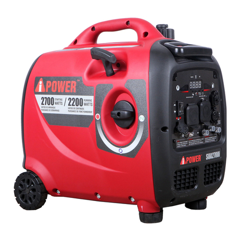
A-iPower PK12000 User manual

Parallel Kit
Owner’s Manual
P/N: 32082-04884-00
Model:
Serial:
Date Purchased:
Model# PK12000 REV00
SAVE THIS MANUAL FOR FUTURE REFERENCE
DO NOT RETURN
TO STORE!
CALL US FIRST
855-888-3598
FOR SUPPORT

Table of Contents
Introduction....................................................................................................................1
Read This Manual Thoroughly...............................................................................................1
Safety........................................................................................................................................1
Definitions And Symbols.......................................................................................................1
Assembly And Operation.................................................................................................3
Set up and Operation............................................................................................................3
Controls And Feature......................................................................................................5
Parts Diagram And Parts List..........................................................................................6
Circuit Diagram..............................................................................................................7
Warranty........................................................................................................................8
Parts Diagram......................................................................................................................6

INTRODUCTION
SAFETY
Read This Manual Thoroughly
The manufacturer cannot possibly anticipate every possible circumstance that might involve a hazard. The
warnings in this manual and the tags and decals affixed to the unit are therefore not all-inclusive. If you use a
procedure, work method or operating technique that the manufacturer does not specifically recommend you
must satisfy yourself that it is safe for you and others. You must also make sure that the procedure work
method or operating technique that you choose does not render the generator unsafe.
If any section of this manual is not understood,
contact customer Service at 855-888-3598, or
www.a-ipower.com for starting, operating and
servicing procedures. The owner is responsible for
proper maintenance and safe use of the unit.
SAVE THESE INSTRUCTIONS for future reference.
This manual contains important instructions that
must be followed during placement, operation and
maintenance of the unit and its components. Always
supply this manual to any individual that will use this
unit.
The information in this manual is accurate based on
products produced at the time of publication. The
manufacturer reserves the right to make technical
updates, corrections and product revisions at any
time without notice.
1
Definitions And Symbols
DANGER
Indicates a hazard
which, if not avoided,
will result in death or
serious injury.
WARNING
Indicates a hazard
which, if not avoided,
could result in death
or serious injury.
NOTICE
Indicates information
considered important,
but not hazard-related
(e.g.,messages relating
to property damage).
CAUTION
Indicates a hazard
which, if not avoided,
could result in minor
or moderate injury.
WARNING
Read and understand manual completely
before using product. Failure to
completely understand manual and
product couldresult in death or serious
injury.
WARNING
Operating, servicing, and maintaining this equipment
can expose you to chemicals including engine
exhaust, carbon monoxide, phthalates, and lead,
which are known to the State of California to cause
cancer and birth defects orother reproductive harm.
To minimize exposure, avoid breathing exhaust, and
wear gloves or wash your hands frequently when
servicing this equipment. For more information go to
www.P65warnings.ca.gov.
The words DANGER, WARNING, CAUTION, and NOTICE are used throughout this manual to highlight important
information. Make sure that the meanings of this safety information is known to all who operate, perform
maintenance on, or are nearthe generator.
This safety alert symbol appears with most safety statements. It means attention,become alert, your
safety is involved! Please read and abide by the message that follows the safety alerts symbol.

WARNING
SAFETY
1. Set up and use only on a flat,level,dry and well-ventilated surface.
2. Inspect thoroughly before each use.Do not use if damaged.
3. Fully insert cable plugs into outlets.Do not use excessive force to make connections.
4. Do not drive,drag or place objects over paralled kit cords.Do not walk on paralled kit cords.
5. Read all safety precautions on generator for instruction manual.
6. This product is for outdoor use only.
7. Do not connect or disconnect parallel kit while generator is running. Doing so can cause permanent
damage not covered under warranty.
8. Do not get the product wet.Do not use if this product is exposed to moisture.
9. If required, use only certified approved extension cords with this product.
10. Do not overload the parallel kit. The kit can supply a maximum of 50 Amps at 240 Volt or 12000 Watts
per outlets depending on the rating of the inverter generators.
11. Do not arallel more than two inverter generators.
12. Link two inverter generators together for 90-95% of the sum of the two inverter wattage rating.
(depends on the models).
13. Use only A-ipower inverters for paralleling.
2

Set Up And Operation(Applicable To All Models)
ASSEMBLY AND OPERATION
This kit is intended for use on A-ipower lnverter
Generators.
Please refer to your Inverter Owner's Manual forsafety
rules, start up and shut down procedures,specifica-
tions and troubleshooting.
5. Turn on both inverters. See inverter owner’s manual
for starting instruction.
lf not spaced apart, the exhaust heat from one unit
may discolor or melt the plastic on the other unit.
2. Inverters to be TURNED OFF and all electrical loads
DlSCONNECTED before installing parallel kit.
NOTE: Do not connect or disconnect the parallel kit
while the inverters are running.
3. The low idle switch(button) must be in the same
position (ON or OFF) on both generators.
4. On each inverter:
4.1 Remove the parallel outlet covers. Plug the black
and red parallel cable terminals to the black and red
parallel outlet (black to black and red to red) on
each corresponding inverters control panel. Do not
plug two red cables or two black cables into the
same inverter.
4.2 Loosen nuts on grounding terminals and attach
round wire to ground terminal in each inverter.
Tighten securely.
3
1. Align the two inverters on a firm, flat and level
surface at a minimum 20 inch apart.
WARNING
If not spaced apart, the exhaust heat
from one generator discolors or melt
the plastic shell on other generator.
20”
5b. Recoil start
Pull recoil starter slowly until resistance is felt,
then pull rapidly.
5a. Electric start
Turn and hold the ENGINE START/STOP
switch for 5 seconds until the engine start.
Parallel Cable
Terminals
Parallel
Outlets
Grouding Wire

NOTE: Make sure the indicator light of overload reset
button(or output indicator) is green on each inverter.
6. The low idle switch(button) must be in the same
position (ON or OFF) on both generators before
applying any load.
7. Plug in the 240 Volt AC, single phase, 60Hz electrical
loads into parallel kit receptacles and turn on first
load. Allow generator output to stabilize before
plugging in the next load.
NOTE : It is strongly recommended to plug in devices
with the largest output first and the smallest output
last to help prevent overloading the inverters. Do not
exceed maximum wattage rating of inverters, parallel
kit and receptacles.
8.When finished, turn off the inverter generators
per owner’s manual instructions and then disconnect
the parallel kit.
ASSEMBLY AND OPERATION
4
5c. Remote start
Turn and hold the REMOTE START switch for 5
seconds until the engine start.

CONTROLS AND FEATURE
5
GEN 1 GEN 2
4
8
1
4
3
5
2
6
7
8
1
3
1 - Grouding Wire
2 - Parallel Kit
3 - Parallel Cable Terminal
4 - Parallel Cable GEN 2
5 - 240V AC 50A 14-50R
6 - Circuit Breakers
7 - 240V AC 30A L6-30R
8 - Parallel Cable GEN 1
9 - Parallel Outlets
10 - Grouding Wire
93
10

PARTS DIAGRAM AND PARTS LIST
6
PARTS DIAGRAM
NO.
1
2
3
4
5
6
7
8
9
10
11
12
13
Qty.
1
1
4
4
1
1
1
1
1
6
1
2
2
Part Number Description
Outlet cover L6-30R
Outlet cover 14-50R
Cross plate head bolt
Parallel box panel
Receptacle L6-30R
Receptacle 14-50R
Circuit breaker amp 50A
Circuit breaker amp 30A
Hex nut
Back cover
Rubber cover
Parallel cable
70001-00965-00
3
1
2
4
5
6
7
12
13
8
9
10
11

Circuit Diagram
50A
30A
50A
14-50R
30A
L6-30R
R
Y/G
L
N
G
B
LNG
CIRCUIT DIAGRAM Model: PK12000
7
B:BLACK
Br:BROWN
G:GREEN
Gy:GRAY
L:BLUE
O:ORANGE
R:RED
W:WHITE
Y:YELLOW
P:PINK
B/W:BLACK/WHITE
Y/G:YELLOW/GREEN
R/W:RED/WHITE

LIMITED WARRANTY
WARRANTY
Warranty Term
WARRANTY
KEEP YOUR RECEIPT. Proof of purchase will be
required to substantiate any warranty claim.
WHAT IS COVERED: A-iPower Corp. warrants to the
original retail purchaser in the United States of
America, or Canada that this product is free of
defects in material and workmanship and agrees, at
A-iPower Corp’s direction, to either repair, provide
replacement parts for, or replace (without charge for
parts or labor) any product or component with a
material defect for a period of 1 year from the date
of purchase, except as limited below. Warranty
service and replacement parts are warranted only for
the duration of the warranty on the original product.
All replaced parts or products become a property of
A-iPower Corp.
This product is also covered by an Emissions Control
System Warranty which is separate from and in
addition to the warranty.
A-iPower Limited Warranty – 1 Year Residential and
120 days Commercial
1 year Residential warranty applies as follow: 1st
year Parts & Labor
A-iPower will provide warranty for any of its products
purchased through any authorized AiPower dealer in
North America to the original purchaser and will be
warranted against defects in material or workmanship
for a period of one (1) year for Consumer use from
date of purchase, subject to exclusions noted herein.
Commercial and Rental applications are warranted for
a period of 120 days from date of purchase.
How to Obtain Warranty Service
DO NOT RETURN THE PRODUCT TO THE PLACE
OF PURCHASE
Please call our Customer Service Dept.
855-888-3598
or e-mail to [email protected]
Please have necessary information available - Model
Number, Serial Number, Proof of Purchase
Warranty Exclusions
This warranty does not cover the following:
Regular wear and maintenance - this warranty will
not cover repair when normal use has exhausted the
lifetime of a part(s) or engine.
Installation and Maintenance - this warranty does not
cover improper or unauthorized assembly, alteration,
modification or any other damage resulting from
misuse or neglect.
Normal maintenance parts - this warranty does not
cover spark plugs, air filters, adjustments, or other
related service due to obstructions and other build
ups resulting from improper maintenance.
Additional exclusions - this warranty does not cover
wearable parts such as filers, spark plugs, o-rings,
batteries etc. It does not cover any cosmetic defects
such as scratches to paint, decals etc. It does not
cover any damage resulting from use of non-original
manufacturer’s parts, use of aftermarket parts. It
does not cover any failures due to acts of God and
A-iPower Customer Service Dept will assist with all
product related questions and will help troubleshoot
issues and will send any replacement parts as
necessary while product is within the warranty period
at no charge. If the issue cannot be resolved then
A-iPower Customer Service Dept at its discretion
determine and authorize diagnosis and repair through
one of its authorized Service Centers. A-iPower Corp
at its discretion may choose to provide replace of
part, component, or product.
Service or replacement of parts at any unauthorized
repair facility without prior authorization will not be
covered by this warranty.
“Consumer Use” - residential household use by a
retail consumer
“Commercial Use” - all other use - commercial ,
business, industrial, or rental purpose
Thank you for choosing A-iPower products. To
ensure proper registration of your product warranty,
please submit your warranty registration along with
proof of purchase within 10 days of the date of
purchase, this can be done by
a) Completing the Warranty Registration form at the
back of this manual and mailing to:
A-IPOWER CORP
10887 COMMERCE WAY UNIT A
FONTANA CA 92337 USA
b) Visit us at www.a-ipower.com and click the
product registration icon
8

other force majeure events beyond the control of the
manufacturer.
Warranty limits and Implications and
Consequential Damages
A-iPower is not obligated to cover any loss of time,
use of product, freight cost, or any other incidental
or consequential claim from the use of this product.
This warranty is in Lieu of all other warranties,
express or implied.
This warranty gives you specific legal rights which
vary from state to state.
MERCHANDISE RETURN GUIDELINES
• All products must be returned in original or
equivalent packaging. Improperly packaged returns
will not be accepted.
• Must have adequate packing for transportation.
• Federal Law requires that all machines that utilize
gasoline, oil, or other flammable liquids must be
drained Completely & Thoroughly prior to shipment.
• Gas caps and oil plugs must be left off for 24
hours prior to shipping. Please note: liability for this
violation of the law resides with the sender of the
shipment.
• Return to address provided in return authorization,
using the parcel service required. Units returned
without authorization will not be honored.
• Please Note: Refunds will not be granted for items
that have been modified or damaged by abuse or
usage not in accordance with product instructions.
WARRANTY
9

A-iPOWER WARRANTY REGISTRATION FORM
Register your product by emailing this form to support@a-ipower.com or register on-line at:
www.a-ipower.com.
Registering your product is important , it provides the following protections:
1. You have record of product purchased
2. Customer Service can Better serve you for Warranty related issues
3.
1.THE PRODUCT WAS PURCHASED FOR: A. Residential cleaning
B. Other ____________________
2.THIS PRODUCT IS A: (select one)
A. First time purchase B. Replacement
3.HOW DID YOU FIRST LEARN OF THIS PRODUCT: (select one)
A. Radio G. Direct Mail
B. Store Display H. From Friend/Relative/Neighbor
C. Contractor I. Internet
D. Trade Show J. Other ____________________
4. PLEASE RATE THE Completly Not at all
FOLLOWING:
5 4 3 2 1
Product Value for Price Paid
Performance
Features
Product Appearance
Warranty
Ease of Maintenance
Noise Level
5 . HOW LIKELY ARE YOU TO RECOMMEND A-iPOWER TO FAMILY OR FRIENDS?
Extremely Not Likely
Likely at all
5 4 3 2 1
Privacy Statement: A-ipower is committed to respecting your privacy and to complying with
the regulations regarding the protection of personal data. The survey data we collect is for
the purposes of marketing or product support and demographic information about the entire
audience registering their products.
Customer Information:
Name: _________________________
Phone: _________________________
E-mail: _________________________
Address: _______________________
City, State: ______________________
Zip code: _______________________
Purchase Date: __________________
Product Information:
Serial #
Model #
The serial No. can be found on the engine.
PLEASE NOTE: Your product cannot be
registered without model & serial numbers.

Fontana, CA 92337 USA
Phone: 855-888-3598
support@a-ipower.com
www.a-ipower.com

Kit Paralelo
Manual Del Usuario
P/N: 32082-04884-00
Modelo# PK12000 REV00
Modelo:
Número de Serie:
Fecha de Compra:
INO LO DEVUELVA
A LA TIENDA!
LLÁMENOS
PRIMERO AL
855-888-3598
PARA PEDIR
APOYO
GUARDE ESTE MANUAL PARA FUTURAS REFERENCIAS

TABLA DE CONTENIDO
Introducción...................................................................................................................1
Lea Este Manual Cuidadosamente.........................................................................................1
Seguridad..................................................................................................................................1
Definiciones y Símbolos.......................................................................................................1
Montaje Y Funcionamiento.............................................................................................3
Configuración y Funcionamiento...........................................................................................3
Controles Y Funciones....................................................................................................5
Dibujos Y listas de Piezas...............................................................................................6
Diagrama Del Circuito.....................................................................................................7
Garantía..........................................................................................................................8
Dibujo de Piezas...................................................................................................................6
1

INTRODUCCIÓN
SEGURIDAD
Lea Este Manual Completamente
El fabricante no puede prever todas y cada una de las circunstancias posibles en las que se podría presentar un
peligro. Por lo tanto, las advertencias en este manual y las etiquetas y calcomanías colocadas en la unidad no
todas están incluidas. Si utiliza un procedimiento, un método de trabajo o una técnica operativa que no sea
específicamente recomendado por el fabricante, debe asegurar que sea seguro para usted y para los demás.
También tendrá que garantizar que el procedimiento, el método de trabajo o la técnica operativa que elija no haga
inseguro el generador.
Si no se entiende alguna sección de este manual,
póngase en contacto con el Servicio al Cliente al
855-888-3598, o www.a-ipower.com para conocer
los procedimientos de arranque, operación y revisión.
El propietario es responsable del mantenimiento
adecuado y uso seguro de la unidad. GUARDE ESTAS
INSTRUCCIONES para futuras referencias. Este
manual contiene instrucciones importantes que se
deben seguir durante la colocación, la operación y el
mantenimiento de la unidad y sus componentes.
Siempre proporcione este manual a cualquier
individuo que utilizará esta unidad.
La información contenida en este manual es precisa
basándose en los productos fabricados en el momento
de la publicación. El fabricante se reserva el derecho
de realizar actualizaciones técnicas, correcciones y
revisiones de productos en cualquier momento sin
previo aviso.
DEFINICIONES Y SÍMBOLOS
PELIGRO
indica un peligro que,
si no se evita, resultará
en la muerte o graves
lesiones.
ADVERTENCIA
Indica un peligro que,
si no se evita, podría
resultar en la muerte o
graves lesiones.
PRECAUCIÓN
Indicates a hazard
which, if not avoided,
could result in minor
or moderate injury.
ADVERTENCIA
Lea y entienda el manual por completo
antes de utilizar el producto. El no
entender completamente el manual y el
producto podría resultar en la muerte o
graves lesiones. ADVERTENCIA
La operación, la revisión y el mantenimiento de este
equipo pueden exponerle a productos químicos
incluidos los gases de escape del motor, el monóxido
de carbono, los ftalatos y el plomo que, conforme al
estado de California, producen cáncer, defectos de
nacimiento u otros daños reproductivos. Para
minimizar la exposición, evite respirar gases de
escape y use guantes o lávese las manos con
frecuencia al revisar este equipo. Para más
información, visite www.P65warnings.ca.gov.
En este manual se emplean las palabras PELIGRO, ADVERTENCIA, PRECAUCIÓN y AVISO para resaltar
información importante. Asegúrese de que el significado de esta información de seguridad se conozca por todos
los que operan, efectúan mantenimientos en o se encuentran cerca del generador.
Este símbolo de alerta de seguridad aparece con la mayoría de las indicaciones de seguridad. Significa
atención, ¡manténgase alerta, su seguridad está involucrada! Lea y obedezca el mensaje que sigue al
símbolo de alerta de seguridad.
AVISO
Indicates information
considered important,
but not hazard-related
(e.g.,messages relating
to property damage).
2

ADVERTENCIA
SEGURIDAD
1. Instalar y utilizar sólo en superficies planas, horizontales, secas y bien ventiladas.
2. Compruebe a fondo antes de cada uso. No usar si está dañado.
3. Inserte el enchufe del cable completamente en el enchufe. No aplique demasiada fuerza cuando se
conecte.
4. No conduzca, arrastre ni coloque objetos en Saltadores de Kit paralelos. No camine sobre cuerdas
paralelas.
5. Lea todas las precauciones de seguridad del generador en las instrucciones.
6. Este producto es sólo para uso al aire libre.
7. Durante el funcionamiento del generador, no conecte ni desconecte el kit paralelo. Esto puede causar
daños permanentes fuera del alcance de la garantía.
8. No humedezca el producto. No utilice este producto si está expuesto a la humedad.
9. Si es necesario, este producto sólo puede utilizar cables de extensión certificados.
10. No sobrecargar el kit paralelo. Dependiendo de la calificación del generador inversor, el kit puede
proporcionar hasta 50 amperios de corriente en cada toma de 240 voltios o 12000 vatios.
11. Los generadores de inversores paralelos no deben exceder de dos.
12. Conecte los dos generadores de inversores juntos para alcanzar el 90 - 95% de la Potencia nominal
total de los dos inversores. (dependiendo del modelo).
13. Sólo el inversor de potencia A-ipower se utiliza en paralelo.
3

Configuración Y Funcionamiento
(Para Todos Los Modelos)
MONTAJE Y FUNCIONAMIENTO
El kit es adecuado para generadores de inversores de
potencia A-ipower.
Consulte el Manual del usuario del inversor para las
reglas de Seguridad, procedimientos de inicio y
cierre, especificaciones y solución de problemas.
5. Encienda los dos inversores. Consulte el Manual del
usuario del convertidor para las instrucciones de
arranque.
3
1. Alinear los dos inversores en una superficie
firme, plana y horizontal con una distancia
mínima de 20 pulgadas.
ADVERTENCIA
Si no hay separación, el calor residual
de un generador puede cambiar de color
o derretir la carcasa de plástico de otro
generador.
20”
5b. Arranque manual de retroceso
Tire lentamente del arranque de retroceso hasta
que se sienta la resistencia y luego tire rápidamente.
5a. Arranque eléctrico
Gire y mantenga el interruptor de arranque / parada
del motor durante 5 segundos hasta que el motor
arranque.
Terminal de
cable paralelo
Socket paralelo
Cable de tierra
Si no hay separación, el calor residual de un disposi-
tivo puede decolorar o derretir el plástico de otro.
2. Antes de instalar el kit paralelo, apague el inversor
y conecte todas las cargas eléctricas.
NOTA: No conecte ni desconecte el kit paralelo
mientras el inversor está funcionando.
3. El interruptor de ralentí bajo (botón) en ambos
generadores debe estar en la misma posición
(ON or OFF).
4. En cada inversor:
4.1 Retire la tapa de salida paralela. Inserte los
terminales de cable paralelo negro y rojo en las
salidas paralelas negras y Rojas (negro a negro,
rojo a rojo) en cada panel de control del inversor
correspondiente. No inserte dos cables rojos o dos
cables negros en el mismo inversor.
4.2 afloje las tuercas de los terminales de puesta a
tierra y conecte los cables circulares a los
terminales de puesta a tierra de cada inversor.
Apriete firmemente.

NOTA: Asegúrese de que la luz indicadora del botón de
reposo de sobrecarga (o indicador de salida) en cada
inversor es verde.
6. El interruptor de ralentí bajo (botón) en ambos
generadores debe estar en la misma posición
(ON or OFF) antes de aplicar cualquier carga.
7. Inserte una carga eléctrica monofásica de 240V
AC de 60 Hz en el enchufe del kit paralelo y abra
la primera carga. Antes de insertar la siguiente
carga, mantenga la salida del generador estable.
NOTA: Se recomienda encarecidamente insertar prime-
ro el dispositivo con la salida máxima y luego el dispos-
itivo con la salida mínima para ayudar a prevenir la
sobrecarga del inversor. No supere la Potencia máxima
del inversor, el kit paralelo y el enchufe.
8. Cuando haya terminado, apague el generador del
inversor de acuerdo con las instrucciones del Manual
del usuario y desconecte el kit paralelo.
MONTAJE Y FUNCIONAMIENTO
4
5c. Arranque remoto
Gire y mantenga pulsado el interruptor de
Arranque remoto durante 5 segundos hasta que
el motor arranque.

CONTROLES Y FUNCIONES
5
1 - Alambre Grouding
2 - Kit Paralelo
3 - Terminal de Cable Paralelo
4 - Cable Paralelo GEN 2
5 - 240V AC 50A 14-50R
6 - Disyuntores
7 - 240V AC 30A L6-30R
8 - Cable Paralelo GEN 1
9 - Puntos de Venta Paralelos
10 - Alambre Grouding
GEN 1 GEN 2
4
8
1
4
3
5
2
6
7
8
1
3
93
10
Table of contents
Languages:
Other A-iPower Portable Generator manuals

A-iPower
A-iPower SUA2000iV User manual

A-iPower
A-iPower SUA12000ED User manual

A-iPower
A-iPower AP5000 User manual

A-iPower
A-iPower SUA7000C User manual

A-iPower
A-iPower SUA5000P User manual

A-iPower
A-iPower AP4000 User manual

A-iPower
A-iPower SUA9000E User manual

A-iPower
A-iPower PK6000 REV00 User manual

A-iPower
A-iPower DUAL FUEL Series User manual

A-iPower
A-iPower SUA12000EAP User manual