A.J.Antunes UF-216C Series User manual

WATER FILTRATION
SYSTEM
UF-216C Series
Owner’s Manual
P/N 1010885 07/04
MANUFACTURING
NUMBERS:
9700405

UF-216 WATER FILTRATION SYSTEM
2P/N 1010885 07/04
UF-216 WATER FILTRATION SYSTEM
3
P/N 1010885 07/04
General
Antunes Filtration Technologies, Division of A.J.
Antunes & Co., has partnered with companies from
around the globe to produce the UF-216 water filtration
systems. The UF-216 removes bacteria and
provides a substantial reduction of viruses that can
enter a typical water supply. This patented technology
is now available to you, sized for your particular appli-
cation. All filter configurations utilize NeoH capillary
membranes, providing the latest innovation in reusable
surface filtration technology.
This manual provides the safety, installation and
operating procedures for the UF-216 water filtration
systems. We recommend that all information contained
in this manual be read prior to installing and operating
the unit.
Your UF-216 unit is manufactured from the finest mate-
rials available and is assembled to AFT’s strict quality
standards. This unit has been tested at the
factory to ensure dependable trouble-free operation.
OWNER INFORMATION
TABLE OF CONTENTS
IMPORTANT! Keep these instructions for future reference. If the unit changes owner-
ship, be sure this manual accompanies the equipment.
Warranty Information
Please read the full text of the Limited Warranty in this
manual.
If the unit arrives damaged, contact the carrier imme-
diately and file a damage claim with them. Save all
packing materials when filing a claim. Freight damage
claims are the responsibility of the purchaser and are
not covered under warranty.
The warranty does not extend to:
• Damages caused in shipment or damage as
result of improper use.
• Installation of electrical service.
• Normal maintenance as outlined in this manual.
• Malfunction resulting from improper maintenance.
• Damage from moisture leaking into electrical
components.
• Normal maintenance as outlined in this manual.
• Damage from tampering with, removal of, or
changing any preset control or safety device.
Owner Information .....................................................2
General......................................................................2
Warranty Information .................................................2
Important Safety Information ....................................3
Service/Technical Assistance ....................................3
Specifications .............................................................5
Electrical Cord & Plug Configurations .......................5
Electrical Ratings.......................................................5
Dimensions................................................................5
Specifications (Filter Cartridges) ...............................5
Components ..............................................................6
Components ..............................................................7
Unpacking..................................................................8
Equipment Setup.......................................................8
Installation...................................................................8
Locating and Mounting the system ...........................9
Flushing and Starting the System ............................9
Operation...................................................................13
Filtration Process.................................................... 13
LED Display ........................................................... 13
Starting the System ................................................ 13
Programming Timer ............................................... 13
Setting the Flush Interval (Fi) ................................. 13
Setting Flush Duration (Fd) .................................... 14
Programming Timer While Unit
is in Flush Interval (Fi) Mode.................................. 15
Manual Flushing ..................................................... 16
Changing the Cartridges ........................................ 17
Manual Flushing ..................................................... 17
Checking the Timer Program.................................. 17
Maintenance..............................................................17
Troubleshooting .......................................................18
Replacement parts UF-216 ......................................19
Wiring Diagram.........................................................23
LIMITED WARRANTY ...............................Back Cover

UF-216 WATER FILTRATION SYSTEM
2P/N 1010885 07/04
UF-216 WATER FILTRATION SYSTEM
3
P/N 1010885 07/04
Purchased From:
Date of Purchase:
Model No.:
Serial No.:
Mfg. No.:
Throughout this manual, you will find the following
safety words and symbols that signify important safety
issues with regards to operating or maintaining the unit.
WARNING
GENERAL WARNING. Indicates informa-
tion important to the proper operation of
the equipment. Failure to observe may
result in damage to the equipment and/or
severe bodily injury or death.
WARNING
ELECTRICAL WARNING. Indicates infor-
mation relating to possible shock hazard.
Failure to observe may result in damage
to the equipment and/or severe bodily
injury or death.
CAUTION
GENERAL CAUTION. Indicates informa-
tion important to the proper operation of
the equipment. Failure to observe may
result in damage to the equipment.
IMPORTANT SAFETY INFORMATION
In addition to the warnings and cautions in this manual,
use the following guidelines for safe operation of the
unit.
• Read all instructions before using equipment.
• For your safety, the equipment is furnished with
a properly grounded cord connector. Do not
attempt to defeat the grounded connector.
• Install or locate the equipment only for its intend-
ed use as described in this manual. Do not use
corrosive chemicals in this equipment.
• Do not operate this equipment if it has a dam-
aged cord or plug; if it is not working properly, or
if it has been damaged or dropped.
• This equipment should be serviced by qualified
personnel only. Contact Antunes Equipment
Manufacturing (Suzhou) Co., Ltd. at 86-512-684-
3637 for repair
• Do not immerse cord or plug in water.
Service/Technical Assistance
If you experience any problems with the installation
or operation of your unit, contact Antunes Equipment
Manufacturing (Suzhou) Co., Ltd. at 86-512-684-3637.
Fill in the information in the next column and have it
handy when calling for assistance. The serial number
is on the specification plate located on the unit.
OWNER INFORMATION (continued)
IMPORTANT
Antunes Filtration Technologies reserves the right to change specifications and product
design without notice. Such revisions do not entitle the buyer to corresponding chang-
es, improvements, additions or replacements for previously purchased equipment.

UF-216 WATER FILTRATION SYSTEM
4P/N 1010885 07/04
UF-216 WATER FILTRATION SYSTEM
5
P/N 1010885 07/04
IMPORTANT SAFETY INFORMATION (continued)
• Keep cord away from heated surfaces.
The following warnings and cautions appear throughout
this manual and should be carefully observed.
• Turn the unit off and disconnect the power source
before performing any service or
maintenance on the unit.
• The equipment should be grounded according to
local electrical codes to prevent the possibility of
electrical shock. It requires a grounded recep-
tacle with separate electrical lines, protected by
fuses or circuit breaker of the proper rating.
• All electrical connections must be in accordance
with local electrical codes and any other appli-
cable codes.
• WARNING ELECTRICAL SHOCK HAZARD.
FAILURE TO FOLLOW THESE INSTRUCTIONS
COULD RESULT IN SERIOUS INJURY OR
DEATH.
- Electrical ground is required on this
appliance.
- Do not modify the power supply cord plug. If
it does not fit the outlet, have a proper outlet
installed by a qualified electrician.
- Do not use an extension cord with this appli-
ance.
- Check with a qualified electrician if you are in
doubt as to whether the appliance is properly
grounded.
• If the supply cord is damaged, it must be
replaced by the manufacturer or its service agent
or a similarly qualified person.
• This equipment is to be installed to comply with
the local plumbing code and any other applicable
code.
• Water pressure must not exceed the membrane
burst pressure of 7 bar (100 psi). To reduce
water pressure, install a water pressure regulator
and set water pressure to suit application. Note
that trans membrane pressure (inlet water pres-
sure minus the permeate water pressure) must
be .5 - 2.5 bar (7 - 36 psi).

UF-216 WATER FILTRATION SYSTEM
4P/N 1010885 07/04
UF-216 WATER FILTRATION SYSTEM
5
P/N 1010885 07/04
SPECIFICATIONS
Electrical Ratings
Electrical Cord & Plug Configurations
Dimensions
CAUTION
All electrical connections must be in accordance
with local electrical codes and any other
applicable codes.
WARNING
ELECTRICAL SHOCK HAZARD.
FAILURE TO FOLLOW THE INSTRUCTIONS IN
THIS MANUAL COULD RESULT IN SERIOUS INJU-
RY OR DEATH.
• Electrical ground is required on this appliance.
• Do not modify the power supply cord plug. If
it does not fit the outlet, have a proper outlet
installed by a qualified electrician.
• Do not use an extension cord with this
appliance.
• Check with a qualified electrician if you are in
doubt as to whether the appliance is properly
grounded.
Specifications (Filter Cartridges)
Maximum Operating Pressure 7 bar (100 psi)
Maximum Operating Temp. 40°C (104°F)
Trans Membrane Pressure 0.5-2.5 Bar (7-36 psi)
pH Range 3-10
MWCO 100 kD
Sanitizing Temp. 80°C (176°F)
Unit A
Width
(inches)
B
Depth
(inches)
C
Height
(inches)
UF-216C 15 inches
(381 mm)
5.5 inches
(139.7 mm)
28 inches
(711.1 mm)
Letter
Code*
Description Configuration
H Harmonized Cord
(H)K* Chinese/Australian
10 Amp, 250 VAC
* Indicates that the plug comes with a Harmonized
Cord.
Voltage Watts Hertz
230 10 50/60
Figure 1. Dimensions
Operating Weight: 39 lbs (17.7 kg)

UF-216 WATER FILTRATION SYSTEM
6P/N 1010885 07/04
UF-216 WATER FILTRATION SYSTEM
7
P/N 1010885 07/04
SPECIFICATIONS (continued)
Figure 2a. Components
Components
Inlet Nipple
Permeate
Nipple
Drain
Nipple
Power Cord
Shroud

UF-216 WATER FILTRATION SYSTEM
6P/N 1010885 07/04
UF-216 WATER FILTRATION SYSTEM
7
P/N 1010885 07/04
LED Display
Program
Button
Power Cord
Filter
Cartridge
Strainer
Permeate
Drain
Inlet
Figure 2b. Components
SPECIFICATIONS (continued)
Components

UF-216 WATER FILTRATION SYSTEM
8P/N 1010885 07/04
UF-216 WATER FILTRATION SYSTEM
9
P/N 1010885 07/04
Unpacking
1. Remove the system and all packing materials
from the chipping carton.
2. Remove all packing materials and protective cov-
erings from the system
3. Remove the information packet. To prevent any
delay in obtaining warranty coverage, fill out and
mail the warranty card.
NOTE: If any parts are damaged, contact Antunes
Equipment Manufacturing (Suzhou) Co. Ltd.
IMMEDIATELY at 88-512-684-3637.
Equipment Setup
GENERAL
When placing the unit into service, pay attention to the
following guidelines:
• Make sure power to the unit is off.
• Do not immerse cord or plug in water.
• Keep cord away from heated surfaces.
ELECTRICAL
Ensure that the line voltage corresponds to the stated
voltage on the units specification label. Make sure that
the plug on the power cord from the system and the
outlet match. For proper operation, and to ensure the
highest quality water from the system, make sure that
the system is not connected to a switched electrical
outlet.
PLUMBING
NOTE: This unit is designed to use tap water not
to exceed 104°F (40°C).
The UF-216 uses the following connections (Figure 1):
• Water Inlet 1/2” NPT
• Permeate (Product Water) 1/2” NPT
• Drain 1/2” NPT
When making a plumbing connection to the system,
remember to use a back-up wrench on the supporting
plumbing. Always use a good quality, approved, pipe
sealant or Teflon tape on pipe threads. Be careful not
to get the pipe sealant inside the pipe when making the
connections.
INSTALLATION
Do not over tighten the connections. It is recommend-
ed that plastic fittings be used when connecting to the
plastic connections of the system. This will reduce the
possibility of cracking the connections due to overtight-
ening.
If soldered plumbing is used, do not apply heat to, or
near, the filtration system. The use of union (O-ring
seal) connections is highly recommended for ease of
installation and future servicing.
SUGGESTED TOOLS AND SUPPLIES FOR INSTALLATION
The following tools and supplies are suggested to make
the installation easier:
• Screwdriver
• Drill with bits
• Strap wrench
(up to 6” diameter)
• Tape measure
• Two gallon bucket
• Fresh 5 1/4% liquid
chlorine bleach
(such as Clorox®)
• Adjustable wrenches
• Pipe wrenches
• Level
• Pipe dope or Teflon
tape
CAUTION
This equipment is to be installed to comply with
the basic plumbing code of the Building Officials
and Code Administrators, Inc. (BOCA) and the
Food Service Sanitation Manual of the Food and
Drug Administration (FDA).
CAUTION
Water pressure must not exceed a membrane
burst pressure of 7 bar (100 psi). To reduce water
pressure, install a water pressure regulator and
set water pressure to suit application. Note that
trans membrane pressure must be .5 - 2.5 bar (7
- 36 psi).

UF-216 WATER FILTRATION SYSTEM
8P/N 1010885 07/04
UF-216 WATER FILTRATION SYSTEM
9
P/N 1010885 07/04
INSTALLATION (continued)
Locating and Mounting the system
Consider these points before mounting the system:
• Note the location of the water supply, drain, and
an appropriate electrical outlet when choosing a
mounting location.
• Remember to allow for access to the timer/
programmer controls.
• Do not mount the system above any electrical
equipment, or items that may be damaged if they
get wet.
• Install the system in a location that will allow for
future service access.
• Mount the system on a wall using appropriate
mounting hardware.
• Remember to consider the operating weight of
the system when choosing mounting hardware.
Depending on the type of wall the system is being
mounted to, wall reinforcement may be necessary.
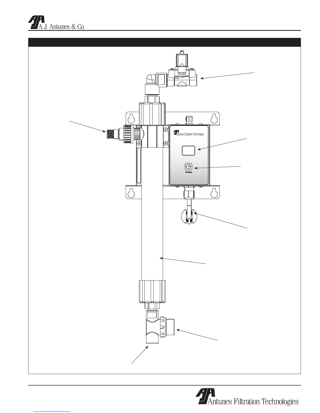
INLET WATER PLUMBING
It is recommended that the inlet water plumbing line
be 1/2”” NPT or larger. A shutoff valve (not supplied)
should be installed in the line leading to the system.
The valve should be mounted close to the system inlet,
and sized properly for the inlet plumbing line. This
valve will allow for easier servicing and future cartridge
change-out.
NOTE: The system should only be connected to the
cold water line.
To ensure that the highest quality water is produced
from the system, the plumbing leading to the filter sys-
tem must be flushed clear of all debris before the sys-
tem is hooked up. Before making the connection to the
inlet of the filter system, hold a bucket or other contain-
er at the inlet water line and slowly open the inlet water
valve. Allow the pipe to flush until all debris is removed.
PERMEATE LINE PLUMBING
To ensure the highest quality and safest water, it is rec-
ommended that a check valve (to prevent back flow) be
installed in the water line after the permeate connec-
tion. This will help prevent possible contamination of
the filter system due to other equipment downstream.
The check valve (not supplied) should be mounted
close to the system outlet, and sized properly for the
plumbing line. Check with local codes for the proper
specification.
DRAIN LINE PLUMBING
The drain line is used to flush away the particle buildup
when cleaning the filter. The drain line must be able
to support the flow rate when the system flushes. The
flow rate from the flush depends on the inlet water pres-
sure, inlet pipe size, and system selected. It is recom-
mended that the drain line be as large as, or larger
than, the inlet plumbing line. The drain line should be
as short as possible, sloping downward without kinks
or loops. Be sure that the drain used is not blocked or
restricted.
The filter system must be protected from possible back
contamination by the installation of an air gap between
the drain connection of the system and the drain
(Figure 3). This gap in the line, with no physical contact
between the system and sewer, prevents contamination
of the system in the event of a backed-up sewer.
NOTE: Make sure that the end of the drain line is
positioned and secured at least 2 inches above
the drain so that the water flow is directed into the
drain, without splashing.
Flushing and Starting the System
FLUSH THE PIPES
To ensure that the highest quality water is produced
from the system, the plumbing leading from the filter
system must be flushed clear of all debris after the
system is hooked up. After making the connection to
the outlet of the filter system, open a faucet or tap clos-
est to the filter system, then slowly open the inlet water
valve. Allow the pipe to flush until all debris is removed.
FLUSH THE MEMBRANE CARTRIDGE
The ultrafiltration membrane cartridge must be flushed
to remove air and the shipping/storage solution. For
maximum quality, the permeate water produced during
the flushing procedure must be discarded. Direct this
permeate water to the drain.
1. Plug the power cord into the appropriate electri-
IMPORTANT
It is recommended that you flush the membrane
cartridge first, without the carbon cartridge
installed in the Carbon Filter Housing, followed
by flushing the carbon cartridge. This prevents
the shipping/storage solution in the membrane
cartridge from entering the carbon cartridge and
ensures that the system produces the highest
quality water.

UF-216 WATER FILTRATION SYSTEM
10 P/N 1010885 07/04
UF-216 WATER FILTRATION SYSTEM
11
P/N 1010885 07/04
Figure 3. Proper Draining
2”
minimum
2”
minimum
Floor
Drain
Secure
End
Drain Line
from System
Drain Line
from System
Secure
End
Drain
Standpipe
INSTALLATION (continued)
cal outlet. The display will power on and the LED
display will display the following for about two sec-
onds each:
• 8.8
• F8 followed by its time settings in seconds
• Fi and its time setting in minutes or hours.
The F8 and Fi sequence repeats for 30 seconds
after which the unit automatically returns to the
Flush Interval Mode (Fi). The time setting for Fi will
be displayed and the decimal point will flash in one
second intervals.
2. Open the tap or faucet closest downstream to the
filter system.
3. Slowly open the inlet water valve and allow water
to enter the system.
4. Press and hold the Start button. After 6-7 sec-
onds, the drain valve will open and FL will appear
on the display.
5. Continue holding the Start button down for at least
CAUTION
Ingesting the protective solution may cause irrita-
tion of the gastrointestinal tract, colic, diarrhea, or
other similar symptoms
30 seconds to keep the drain open. This flushes
air out of the center of the hollow fibers. The
drain will remain open as long as the Start button
is pressed. Check to make sure that the drain
water is directed into the drain without splashing.
6. Release the Start button. This closes the drain
valve. Water should continue to flow through the
system and out of the open tap. Allow water to
flow out of the tap for at least 15 minutes at maxi-
mum flow rate.
7. Close the tap and let the system stand with no
water flow for 15 minutes to allow any trapped air
to come out of the hollow fibers. Check for leaks
at all fittings.
8. After 15 minutes without water flow, open the
tap for 5 minutes to allow any trapped air to be
flushed out.
9. Close the tap. Flushing of the membrane car-
tridge is complete.
INSTALL AND FLUSH THE CARBON FILTER CARTRIDGE

UF-216 WATER FILTRATION SYSTEM
10 P/N 1010885 07/04
UF-216 WATER FILTRATION SYSTEM
11
P/N 1010885 07/04
INSTALLATION (continued)
Refer to the figure to the right and follow the Steps
below to install and flush the Carbon Cartridge.
1. Shut off the water to the system using the inlet
water valve.
2. Open the tap or faucet closest downstream to the
filter system to relieve pressure in the system.
3. Unscrew the Carbon Filter Housing, remove the
old Carbon Filter and discard any water inside the
housing.
4. Remove the plastic wrap and labels from the new
carbon cartridge. Make sure the rubber gaskets
are in place on both ends of the Carbon Cartridge
before inserting into the Carbon Filter Housing.
Place the Carbon Cartridge into the Housing and
screw the Housing up into the Filter Housing Cap
5. Slowly open the inlet water valve and allow water
to enter the system.
6. Water should flow through the system and out of
the open tap. Allow water to flow out of the tap
for at least 5 minutes at maximum flow rate. After
5 minutes of flushing, close the tap.
7. Press and hold the Start button for at least 30
seconds to flush air out of the center of the hollow
fibers of the membrane cartridge.
8. Release the Start button. Flushing of the system
is complete.
SANITIZING THE SYSTEM AND LINES
O-Ring
Rubber Gasket
Rubber Gasket
Carbon Filter
Cartridge
Carbon Filter
Housing
Filter Housing
Cap

UF-216 WATER FILTRATION SYSTEM
12 P/N 1010885 07/04
UF-216 WATER FILTRATION SYSTEM
13
P/N 1010885 07/04
The plumbing must be sanitized to eliminate possible
contamination that may have occurred during the instal-
lation process. Chlorine bleach can be used to sanitize
the plumbing. The amount of bleach to use depends
on the system installed and the amount of plumbing
downstream of the filter system. Generally, 1 ounce
(30 ml) of bleach will be sufficient to sanitize the sys-
tem.
1. Make sure that the system has been flushed of
air and debris as described in the Flushing and
Starting up the System section of this manual.
2. Open the tap closest downstream to the filter sys-
tem.
3. Close the inlet water valve and allow the system
to depressurize.
4. Place a bucket under the strainer at the inlet
connection to the system. Open the strainer by
unscrewing the cap. Water will flow out of the
strainer as the system drains.
5. When the water flow out of the strainer stops,
pour the liquid bleach into the strainer. Be care-
ful not to spill bleach onto clothing or skin. You
may want to add the bleach using a cup or fun-
nel. Reattach the cap on the strainer or the inlet
plumbing line.
6. Slowly open the inlet water valve and allow water
to flow out of the tap until the smell of bleach is
present.
7. Close the tap and let the system stand with no
water flow for at least 15 minutes to allow the
bleach to sanitize the pipes.
8. After 15 minutes without flow, open the tap and
flush until the presence of bleach is gone. All
other taps should be opened to flush any bleach
from the plumbing.
9. Close the tap. The sanitization is complete.
10. Remember to reinstall the carbon cartridge as
described in the Install and Flush the Carbon
Cartridge section of this manual.
Program the timer following the procedure outlined in
the Operation section of this manual.
INSTALLATION (continued)
IMPORTANT
The carbon cartridge must be removed from the
filter system during the sanitization process.

UF-216 WATER FILTRATION SYSTEM
12 P/N 1010885 07/04
UF-216 WATER FILTRATION SYSTEM
13
P/N 1010885 07/04
Programming Timer
NOTE: Once the UF-216 unit is powered up, the
LED display cycles through the default or current
settings: Flush Duration (Fd) and its setting will
be followed by Flush Interval (Fi) and its settings.
At any time during this sequence, which lasts
approximately 30 seconds the UF-216 unit can be
programmed.
Setting the Flush Interval (Fi)
1. When Fi (Figure 5) is displayed, press and
release start button to view current setting .
2. To make a change, press and hold down start
button to scroll through settings - release button
at desired setting (Figure 6).
3. After ten seconds, unless start button is
depressed, unit automatically returns to
Flush Interval Mode.
NOTE: Fi times are displayed in ten minute inter-
vals, after fifty minutes they are displayed in hours
(Table A).
Filtration Process
Water filtration in the UF-216 is accomplished using
two modes: Flush Interval Mode, shown as Fi on the
LED Display and Flush Duration Mode (Fd on LED dis-
play). During the Flush Interval, water enters the inlet
and flows through the filter element before exiting the
Permeate outlet as usable product water.
After a certain period of time, depending upon water
quality, the filter has to be cleaned. This is accom-
plished through the Flush Duration Mode. During
this mode, the drain valve opens and flushes the
membrane to remove debris collected inside the
membrane walls.
NOTE: Both the Flush Interval Mode and the Flush
Duration Mode can be automated by programming
the timer. During the Flush Interval Mode, the valve
is not powered in order to keep water filtering during
a power outage.
Figure 4. LED Display, Front Panel
LED Display
Fi - Flush Interval Mode is the time between flushes
and is displayed in minutes or hours.
Fd - Flush Duration Mode is the amount of time used
to flush and remove debris from filter cartridge and
is displayed in seconds.
FL - Manual Flush Mode operation, solenoid is
manually activated by the user.
Starting the System
Power up the unit.
The LED read-out displays the following for about two
seconds each:
1. 8.8
2. Fd followed by its time settings in seconds.
3. Fi and its time setting, in minutes or hours.
The Fd, Fi sequence repeats for 30 seconds
after which, the unit automatically returns to the
Flush Interval Mode (Fi). The time setting for Fi
will be displayed and the decimal point will flash in
one second intervals.
NOTE: The timer can be programmed immediately
after start-up or while in Flush Interval Mode.
OPERATION

UF-216 WATER FILTRATION SYSTEM
14 P/N 1010885 07/04
UF-216 WATER FILTRATION SYSTEM
15
P/N 1010885 07/04
OPERATION (continued)
Figure 7. LED Display for Flush Duration Mode
Figure 8. Time Setting Fd Mode (55 Seconds)
Table A. LED Display Settings
Figure 6. Time Setting Fi Mode (22 Hours)
Figure 5. LED Display for Flush Interval Mode
Setting Flush Duration (Fd)
2. When Fd is displayed, press and release start but-
ton to view current setting (Figure 7).
3. To make a change, press and hold down start
button to scroll through settings - release button
at desired setting (Figure 8).
4. After ten seconds, unless button is depressed,
unit automatically returns to Flush Interval Mode.
NOTE: Fd times are displayed in 5 second intervals
up to 60 seconds (Table A).
1- 10 minutes 5 5 seconds
5- 50 Minutes 10 10 seconds
01 1 Hour 15 15 Seconds
12 12 Hours 30 30 Seconds
24 24 hours 60 60 Seconds
Fi - Flush Interval Mode Fd - Flush Duration Mode

UF-216 WATER FILTRATION SYSTEM
14 P/N 1010885 07/04
UF-216 WATER FILTRATION SYSTEM
15
P/N 1010885 07/04
OPERATION (continued)
Programming continued
Programming Timer While Unit is in Flush
Interval (Fi) Mode
TO SET Fi - FLUSH INTERVAL MODE
NOTE: After power-up and cycling - Fi time setting
displays a flashing decimal point.
1. Press and hold down start button for four
seconds. Release button, LED will display. Fd
followed by its setting.
2. When Fi (Figure 7) is displayed, press and release
button to view current setting.
3. To make a change, press and hold down start but-
ton to scroll through settings - release button at
desired setting (Figure 8).
4. After ten seconds, if start button is not pressed, unit
automatically returns to Flush Interval Mode.
NOTE: Fi times are displayed in ten minute intervals,
after fifty minutes they are displayed in hours (Table
B).
TO SET Fd - FLUSH DURATION MODE
1. Press and hold down start button for four
seconds. Release button, LED will display. Fd.
2. When Fd is displayed (Figure 9), press and
release button to view current setting .
3. To make a change, press and hold down start
button to scroll through settings - release button
at desired setting (Figure 10).
4. After ten seconds, if start button is not pressed
unit automatically returns to Flush Interval Mode.
NOTE: Fd times are displayed in 5 second intervals
up to 60 seconds (Table B).
Figure 11. LED Display for Flush Duration
Figure 12. Time Display for Fd Mode (15 Seconds)
Table B. LED Display Settings
Figure 10. Time display for Fi Mode (30 Minutes)
Figure 9. Fi - LED Display for Flush Interval Mode
1- 10 minutes 5 5 seconds
5- 50 Minutes 10 10 seconds
01 1 Hour 15 15 Seconds
12 12 Hours 30 30 Seconds
24 24 hours 60 60 Seconds
Fi - Flush Interval Mode Fd - Flush Duration Mode

UF-216 WATER FILTRATION SYSTEM
16 P/N 1010885 07/04
UF-216 WATER FILTRATION SYSTEM
17
P/N 1010885 07/04
Manual Flushing
NOTE: Manual flushing only works when unit is in
Flush Interval Mode (Fi).
While the unit is in Flush Interval Mode (decimal point
flashing), hold the start button down for 6-7
seconds until the LED displays FL (Figure 11).
Continue holding the button down to keep the drain
open. Drain will remain open for as long as start button
is depressed. (FL will flash on LED.) Releasing the but-
ton closes the drain and puts the unit back into startup
mode. After ten seconds, if the start button is not pressed
the unit automatically returns to the Flush Interval Mode
(Fi).
Figure 13. Manual Flush
OPERATION (continued)

UF-216 WATER FILTRATION SYSTEM
16 P/N 1010885 07/04
UF-216 WATER FILTRATION SYSTEM
17
P/N 1010885 07/04
MAINTENANCE
The filtration system is designed to require very little
maintenance. To ensure that the water is of the highest
quality, occasionally some service is required.
Manual Flushing
NOTE: Manual flushing only works when the unit is
in Flush Interval mode (Fi).
While the unit is in Flush Interval mode (decimal point
flashing), hold the Start button down for 6-7 seconds
until the LED displays FL (Figure 14).
Continue holding the button down to keep the drain
open. The drain will remain open for as long as the
Start button is pressed (FL will flash on the LED dis-
play).
Releasing the Start Button closes the drain and puts
the unit back into start up mode. After ten seconds, if
the Start Button is not pressed the unit automatically
returns to Flush Interval mode (Fi).
Checking the Timer Program
During normal operation, the system displays the time
setting for the Flush Interval Mode (Fi) and the decimal
will flash in one second intervals.
NOTE: This is the time between flushing, not a time-
of-day setting.
Over time, it is possible that the system flush will occurs
at a time of high water use. If this creates a problem,
the timer can be reset by unplugging the power cord,
waiting for 5 seconds, and plugging the power cord
in again. The timer then begins timing from the point
power is restored to the system. Follow the procedures
within the Operation section of this manual to check
and set the timer settings.
Changing the Cartridges
The UF-216 system uses two types of filtration: Carbon
Block filtration and capillary membrane filtration. While
the filtration system is designed for long life, eventually
the cartridges will need to be replaced.
CHANGING THE CARBON FILTER CARTRIDGE
To change the Carbon Filter Cartridge, follow the steps
under Install and Flush the Carbon Filter Cartridge
in the Installation section of this manual.
CHANGING THE CAPILLARY MEMBRANE FILTER
CARTRIDGE
1. Open the faucet or tap closest downstream to the
filtration system and close the inlet water valve
and allow the system to depressurize.
2. Place a bucket under the strainer at the inlet
connection to the system. Open the strainer by
unscrewing the cap. Water will flow out of the
strainer as the system drains.
3. Press and hold the Start button to help drain the
system.
4. Reattach the cap on the strainer when the water
flow stops. Unplug the power cord.
5. Using a strap wrench (up to 6” capacity), loosen
the top and bottom end caps. DO NOT remove
the top and bottom End Caps yet.
6. Disconnect the permeate port connection.
7. Using a screwdriver, remove the screws from the
cartridge bracket and set the bracket and screws
aside.
8. Unscrew the cartridge end caps from the car-
tridge, being careful to retain the O-rings from
each cap. Set the O-rings aside.
9. Install a new cartridge to the system using the
cartridge bracket and screws saved from Step 8.
10. Connect the permeate port connection.
11. Inspect the O-rings to make sure they are clean
and are not splitting or cut. For all O-rings, make
sure they are lubricated with an approved food
grade lubricant acceptable for drinking water use.
12. Screw the cap onto the cartridge. Tighten with
strap wrench as necessary.
13. Follow the Flushing and Starting the System and
Sanitizing the System and Lines procedures in the
Installation section of this manual to complete the
cartridge change.
SYSTEM SANITIZATION
Over time and use, the plumbing downstream from the
system may require sanitization. It is recommended
that the system and downstream plumbing be sani-
tized at least once a year. When necessary, follow the
Sanitizing the System and Lines procedure in the
Installation section of this manual.

UF-216 WATER FILTRATION SYSTEM
18 P/N 1010885 07/04
UF-216 WATER FILTRATION SYSTEM
19
P/N 1010885 07/04
TROUBLESHOOTING
Problem Possible Cause Corrective Action
Unit does not have power. The power cord is not correctly
plugged in.
Plug power cord in correctly.
The Control Display is blank. The power cord is not correctly
plugged in.
Plug power cord in correctly.
Control Board is inoperable. Contact your maintenance person or
Authorized Service agency.
Transformer is inoperable.
No water comes out of the
filter system
Inlet Valve closed. Open the Inlet Valve.
Inlet Strainer is plugged. Clean/replace Inlet Strainer.
End of the capillaries plugged. Clean/replace Ultrafilter Cartridge.
Carbon Cartridge Filter plugged. Replace Carbon Cartridge Filter.
Low water flow/pressure out of
system
See above. See above.
The system may be in a flush cycle. Wait for the flush cycle to end.
Flushing program not set correctly for
water conditions.
Decrease the flush interval and increase the
flush duration (refer to the Operation section
of this manual).
Drain Valve is stuck open. Clean/replace/rebuild the Drain Valve.
The inlet water pressure is too low. Boost the inlet water pressure/replace pipes.
Water tastes bad. Storage/shipping solution not com-
pletely flushed out of system.
Flush system for a longer period of time.
Carbon Cartridge Filter has reached or
exceeded it’s filtration capacity.
Replace the Carbon Cartridge Filter.
Biological growth in pipes. Sanitize plumbing.
Water conditions changed. Consider installing additional filtration.
Broken capillary in Filter Cartridge. Replace Filter Cartridge.
Flush runs continuously. Drain Valve stuck open. Clean/replace/rebuild the Drain Valve.
Controller sending continuous signal
to valve.
Replace the controller.
Flush runs too long. Program duration set too long. Re-program the unit to flush for a shorter
duration of time.
Flush occurs at time of high
water usage.
The Flush Interval is set to interfere
with water use.
Change Flush Interval/reprogram time.
Unplug unit and plug in at a time of lower
water usage.
Water splashes at drain during
flush.
Drain line not positioned properly. Reposition the end of the drain line.
Water leaks at the ends of the
Filter Cartridge after changing
cartridges.
Cartridge end connections are not tight
enough.
Tighten with strap wrench if necessary.
O-rings not lubricated. Lubricate O-rings with food-grade lubricant.
O-rings are split, cut, or twisted Replace O-rings.
Water leaks from Permeate
port.
Permeate port is not tight enough Tighten, with strap wrench if necessary.
O-ring not lubricated. Lubricate O-ring with food-grade lubricant.
O-ring split, cut, or twisted. Replace O-ring.
Water leaks from system fitting
or connection.
Fitting broken or loose. Retighten or replace the fitting.
Not enough pipe thread sealant used. Redo the fitting with the proper amount of
sealant.

UF-216 WATER FILTRATION SYSTEM
18 P/N 1010885 07/04
UF-216 WATER FILTRATION SYSTEM
19
P/N 1010885 07/04
REPLACEMENT PARTS UF-216

UF-216 WATER FILTRATION SYSTEM
20 P/N 1010885 07/04
UF-216 WATER FILTRATION SYSTEM
21
P/N 1010885 07/04
REPLACEMENT PARTS UF-216 (continued)
1 3100183 Screw, TAP #10-24 x 3/4” 4
PHPANHD T-F T/C
2 0504250 Back Plate 1
3 2190149 Nipple, 4” 3
4 0700354 Power Cord 1
5 1030784 Spec. Label 1
6 0011809 Filter Housing, 10” 1
7 1001149 Label, Shroud 1
8 2090139 Cartridge, Carbon Block 1
9 3080103 Screw, MACH. #8-32 x 1/4” 1
Item Part Description Qty.
No.
Item Part Description Qty.
No.
SLTRSHD
10 1001083 Label, Drain 1
11 0504251 Shroud 1
12 0200246 O-Ring, Filter Housing Sump 1
13 2180206 Cap Filter Housing 1
14 2140144* Tape, Pipe Thread, Teflon 1
15 0400138* Lock Nut, Conduit 1/2” NPT 1
16 1001081* Label, Inlet 1
17 1001134* Label, Permeate 1
18 1010885* Owner’s Manual 1
Table of contents
Other A.J.Antunes Water Filtration System manuals
Popular Water Filtration System manuals by other brands

JohnDow Industries
JohnDow Industries AFC-100-94 owner's manual

CAS
CAS Talline Installation & operating instructions

Aquatlantis
Aquatlantis tecatlantis CLEANSYS PRO 730 operating manual

Schoner Wassertechnik
Schoner Wassertechnik EDGE infinity MRO1791A-400G manual

H3C
H3C LSUM110504DUST user manual

Brita
Brita PURITYHEADPLV installation instructions