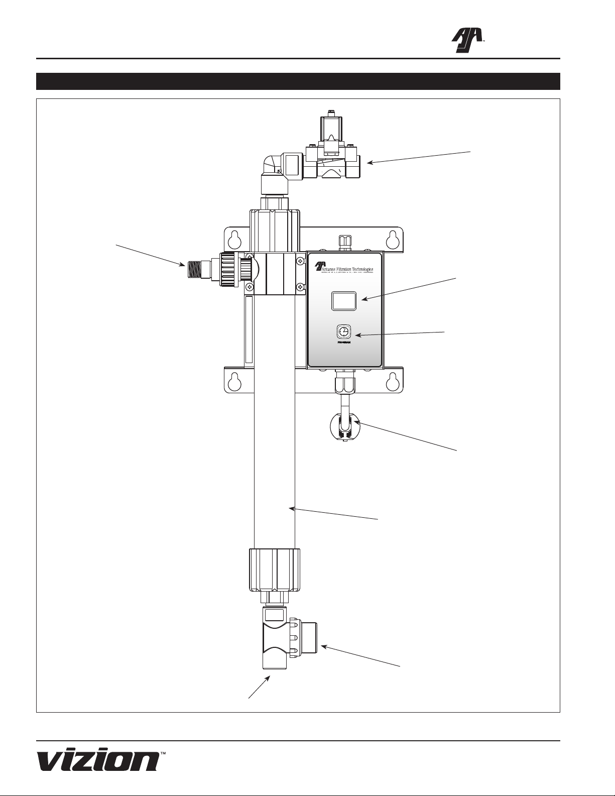
UF SERIES WATER FILTRATION SYSTEM
2
A.J. Antunes & Co.
P/N 1010808 Rev. E 03/12
General
VIZION of A.J. Antunes & Co., has partnered with
companies from around the globe to produce the UF
Series water filtration systems. The UF Series removes
bacteria and provides a substantial reduction of viruses
that can enter a typical water supply. This patented
technology is now available to you, sized for your par-
ticular application. All filter configurations utilize NeoH
capillary membranes, providing the latest innovation in
reusable surface filtration technology.
This manual provides the safety, installation and
operating procedures for the UF-Series water filtration
systems. We recommend that all information contained
in this manual be read prior to installing and operating
the unit.
Your UF-Series unit is manufactured from the finest
materials available and is assembled to our strict
quality standards. This unit has been tested at the
factory to ensure dependable trouble-free operation.
OWNER INFORMATION
TABLE OF CONTENTS
IMPORTANT! Keep these instructions for future reference. If the unit changes
ownership, be sure this manual accompanies the equipment.
Warranty Information
Please read the full text of the Limited Warranty in this
manual.
If the unit arrives damaged, contact the carrier imme-
diately and file a damage claim with them. Save all
packing materials when filing a claim. Freight damage
claims are the responsibility of the purchaser and are
not covered under warranty.
The warranty does NOT extend to:
result of improper use.
components.
changing any preset control or safety device.
Owner Information .....................................................2
General......................................................................2
Warranty Information .................................................2
Important Safety Information ....................................3
Service/Technical Assistance ....................................3
Electrical Cord & Plug Configurations .......................5
Specifications .............................................................5
Electrical Ratings.......................................................5
................................................................5
Specifications (Filter Cartridges) ...............................5
Specifications .............................................................6
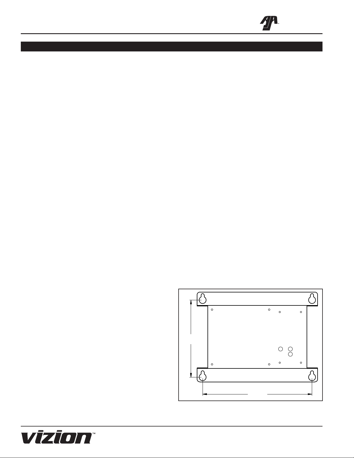
Installation...................................................................7
Unpacking..................................................................7
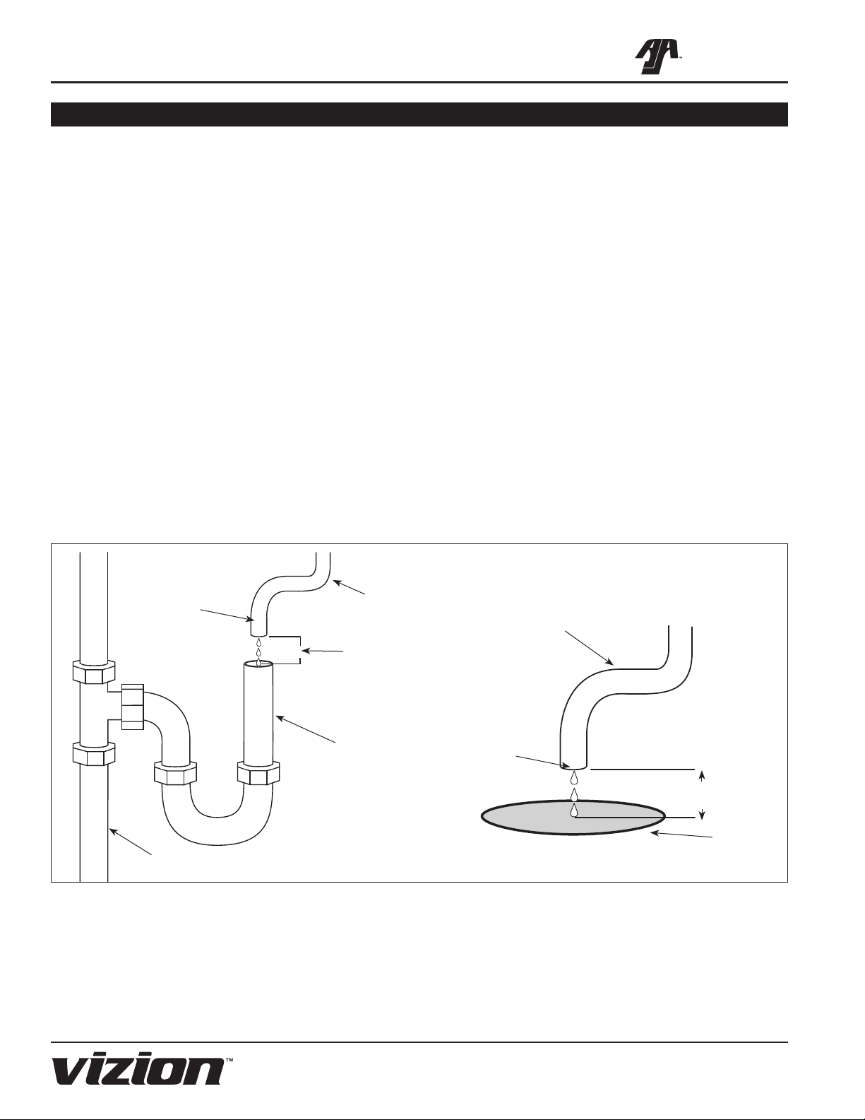
Equipment Setup.......................................................7
...........................8
Filtration Process.....................................................11
.............................................................11
Operation................................................................... 11
Starting the System .................................................11
.........................12
Setting the Flush Interval (FI)..................................12
.....................................12
Checking the Timer Program...................................14
Changing the Cartridges .........................................14
Maintenance..............................................................14
......................................................14
Troubleshooting .......................................................15
Replacement Parts UF-216/224...............................16
Wiring Diagram.........................................................18
Notes..........................................................................19
LIMITED WARRANTY ...............................Back Cover