3
INSPECT SHIPMENT
There may be hidden damage caused in transit. Check to be certain
all parts of the venting system, as listed below, are present. Inspect
the upper and lower air inlet boxes, rear air tube and all parts of the
venting system. CAUTION!!! IF THERE ARE ANY DAMAGED
PARTS, DO NOT INSTALL THIS WATER HEATER. REPORT ANY
SHORTAGE TO YOUR DISTRIBUTOR OR DAMAGE TO YOUR
CARRIER.
VENT KIT ASSEMBLY COMPONENTS
1 — 3" 90° steel elbow
1 — 5" 90° aluminum elbow
1 — 3" tube assembly (2-pcs. meshed)
1 — 5" tube assembly (2-pcs. meshed)
1 — Finishing collar (inside)
1 — Finishing collar (outside)
1 — Terminal Vent Cap Assembly
1 — Tube silicone sealant
8 — Sheet metal screws
GENERAL SAFETY INFORMATION
EXTERNAL DAMAGE
Do not operate the water heater until it has been fully checked out
by a qualified technician, if the water heater:
•Has been exposed to fire or damage.
•Displays evidence of sooting.
•Produces steam or unusually hot water.
If the water heater has been flooded it must be replaced.
CHEMICAL VAPOR CORROSION
WARNING
CORROSION OF THE FLUEWAYS AND VENT SYSTEM MAY
OCCUR IF AIR FOR COMBUSTION CONTAINS CERTAIN
CHEMICAL VAPORS. SUCH CORROSION MAY RESULT IN
FAILURE AND RISK OF ASPHYXIATION.
Spray can propellants, cleaning solvents, refrigerator and air
conditioning refrigerants, swimming pool chemicals, calcium and
sodium chloride (water softener salt), waxes and process chemicals
are typical compounds which are potentially corrosive.
Do not store products of this sort near the heater. Also, air which is
brought in contact with the heater should not contain any of these
chemicals. If necessary, uncontaminated air should be obtained
from remote or outside sources. The limited warranty is voided
when failure of water heater is due to a corrosive atmosphere. (Refer
to the limited warranty for complete terms and conditions).
EXTENDED NON-USE PERIODS
WARNING
HYDROGEN GAS CAN BE PRODUCED IN A HOT WATER
SYSTEM SERVED BY THIS HEATER THAT HAS NOT BEEN USED
FOR A LONG PERIOD OF TIME (GENERALLY TWO WEEKS OR
MORE). HYDROGEN GAS IS EXTREMELY FLAMMABLE. To
reduce the risk of injury under these conditions, it is recommended
that the hot water faucet be opened for several minutes at the kitchen
sink before using any electrical appliance connected to the hot water
system. If hydrogen is present, there will probably be an unusual
sound such as air escaping through the pipe as the water begins to
flow. THERE SHOULD BE NO SMOKING OR OPEN FLAME NEAR
THE FAUCET AT THE TIME IT IS OPEN.
INSULATION BLANKETS
Insulation blankets available to the general public for external use
on gas water heaters are not necessary with A. O. Smith products.
The purpose of an insulation blanket is to reduce the standby heat
loss encountered with storage tank water heaters. Your A. O. Smith
water heater meets or exceeds the National Appliance Energy
Conservation Act standards with respect to insulation and standby
loss requirements, making an insulation blanket unnecessary.
WARNING
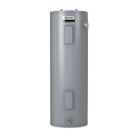
Should you choose to apply an insulation blanket to this heater,
you should follow these instructions (See Figure 1 for identification
of components mentioned below). Failure to follow these
instructions can restrict the air flow required for proper combustion,
resulting in fire, asphyxiation, serious personal injury or death.
•Do not cover the outer door, thermostat or temperature &
pressure relief valve.
•Do not cover the instruction manual. Keep it on the side of the
water heater or nearby for future reference.
•Do obtain new warning and instruction labels from A.O. Smith
for placement on the blanket directly over the existing labels.
INSTALLATION
REQUIRED ABILITY
INSTALLATION OR SERVICE OF THIS WATER HEATER
REQUIRES ABILITY EQUIVALENT TO THAT OF A LICENSED
TRADESMAN IN THE FIELD INVOLVED. PLUMBING, AIR
SUPPLY, VENTING AND GAS SUPPLY ARE REQUIRED.
GENERAL
The installation must conform to these instructions and the local
code authority having jurisdiction. In the absence of local codes,
conform to the latest edition of National Fuel Gas Code ANSI Z223.1
The code manual can be purchased from the American Gas
Association Laboratories, 8501 East Pleasant Valley Road,
Cleveland, OH 44131.
LOCATION OF HEATER
This is a direct vent water heater which draws combustion air from
outside the structure and exhausts all products of combustion to
the outside of the structure. All air for combustion and all products
of combustion are routed through the ducting provided, directly
from and to the outside of the building. It therefore must be located
next to the outside wall within the range of the adjustments illustrated
in fig. 15. DO NOT attempt to extend the air supply tube or inner
flue vent tube beyond the dimensions specified on page 7 vent
connections, steps 6 and 7.
The heater is design certified by the American Gas Association for
installation on combustible flooring in a closet having minimum
clearances from combustible material of: 0" clearance from sides,
rear, and top air tube, 4" from the front and 18" from the top. If
clearances stated on the heater differ from standard clearances,
install water heater according to clearances stated on heater.
A minimum clearance of 4" must be allowed for access to re-
placeable parts such as the thermostats, drain valve and relief valve.
Adequate clearance for servicing this appliance should be
considered before installation, such as changing the anodes, etc.
When installing the heater, consideration must be given to proper
location. The water heater should be located as close to or
centralized to the water piping system as possible. The water heater
should be located in an area not subject to freezing temperatures.
