AAF HermanNelson IM 725 User manual

AAF®-HermanNelson®Classroom Unit Ventilators
©2002 AAF®-HermanNelson®
Installation Manual IM 725
Group: Unit Ventilator
Part Number: 106506101
Date: January 2002
Vertical Floor Models AVS, AVV, AVB, and AVR
Horizontal Ceiling Models AHF, AHB, AHV, and AHR
Before beginning installation, please read this publication in its entirety.
Develop a thorough understanding before starting the installation procedure.
This manual is to be used by the installer as a guide. Each installation is unique, only general topics are covered.
The order in which topics are covered may not be those required for the actual installation.
IMPORTANT!

2IM 725 (1-02)
Table of Contents
Safety Information and Tools Required ............................................................ 2
Pre-Installation Considerations ......................................................................... 2
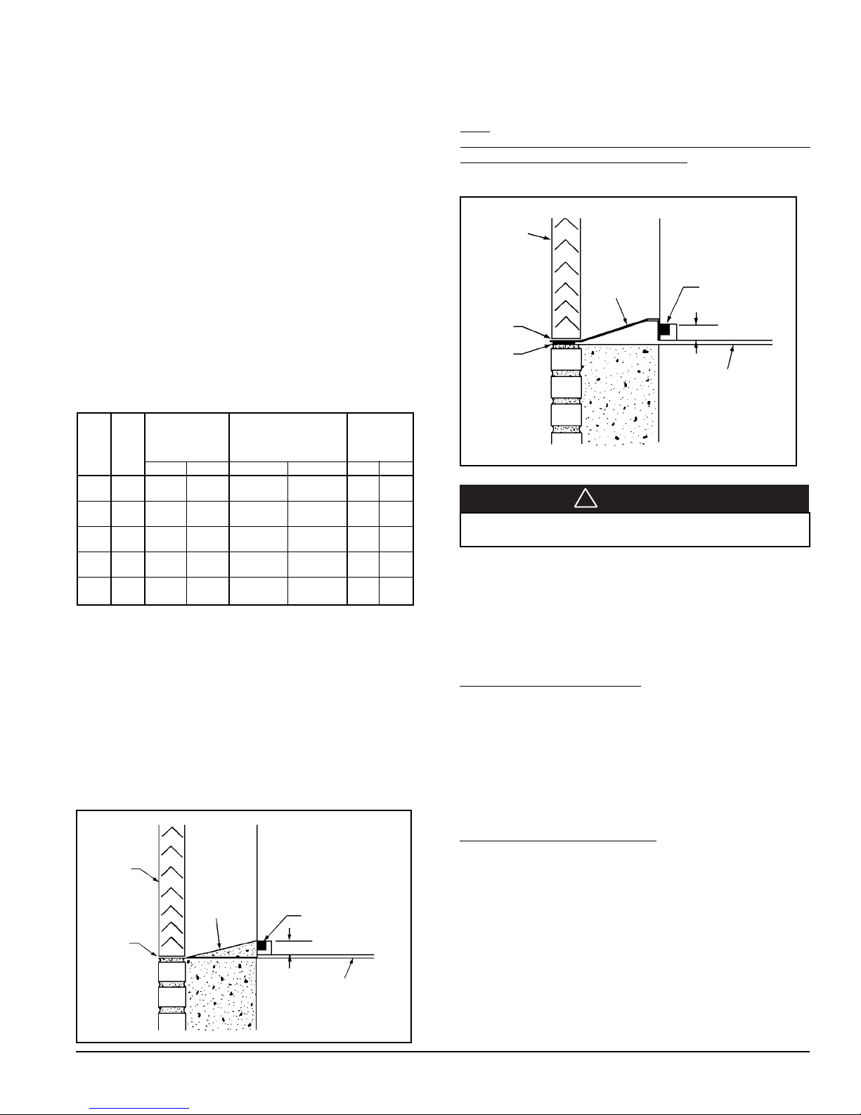
Wall Openings, Louvers, and VentiMatic Shutter ............................................ 3
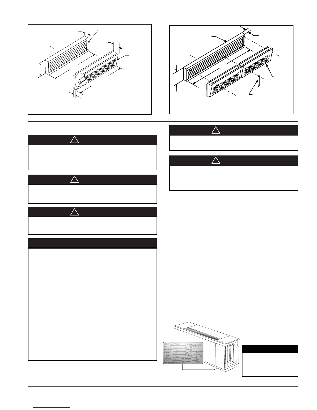
Installing Louvers .............................................................................................. 7
Installing the VentiMatic Shutter Assembly ...................................................... 8
Installing The AV Unit Ventilator .............................................................. 9
Step 1 - Uncrate and Inspect the Unit Ventilator(s) .......................................... 9
Model AV Data Plate - Specific Information ................................................... 10
Step 2 - Position the Unit Ventilator ............................................................ 11-12
Step 3 - Make Piping Connections .................................................................. 12
In All Systems .................................................................................................. 12
In Water Systems ............................................................................................ 13
Coil Header, Locations ............................................................................... 14-16
(Heating Only, Cooling Only) ..................................................................... 14
(Heat/Cool) ................................................................................................. 15
(Reheat) ...................................................................................................... 16
Valves and Piping (diagrams and dimensions) ......................................... 17-19
2-Way and 3-Way End of Cycle Valves ..................................................... 17
2-Way and 3-Way Modulating Valves ........................................................ 18
End of Cycle (In Steam Systems) Valve Piping ........................................ 19
Typical Coil Piping ...................................................................................... 20-21
Condensate Piping .......................................................................................... 22
Unit Ventilator Split Systems Guidelines (DX) Systems ........................... 23-25
Step 4 - Make Electrical Connections .............................................................. 26
Unit Mounted MicroTech™ Direct Digital Controls (DDC) Components .... 27-28
Typical Wall Mounted Room Air Sensor ......................................................... 29
Step 5 - Prepare AV Unit Ventilator for Start-up ............................................. 30
Installing Unit Ventilator End Panels .............................................................. 30
Oiling the Fan Shaft Bearing ........................................................................... 30
AV Unit Ventilator Start-Up ............................................................................. 30
Model AH Ceiling Unit Installation .......................................................... 31
Safety Information and Tools Required .......................................................... 31
Model AH Data Plate - Specific Information ................................................... 32
Typical Ceiling AH Unit Air Arrangements ................................................ 33-34
Pre-Installation Condsiderations ..................................................................... 34
Duct System Design for Noise Control ...................................................... 35-36
Anchoring The Ceiling Unit ............................................................................. 36
Filters ............................................................................................................... 37
Same End Piping Connections ....................................................................... 37
Remote Two Speed Control Switch ................................................................ 38
Prepare AH Ceiling Unit Ventilator for Start-up ............................................. 39
Installing AH Unit Ventilator End Panels ........................................................ 39
Check, Test and Start Warranty Notice .......................................................... 39
Warranty .......................................................................................................... 39
Tools Required
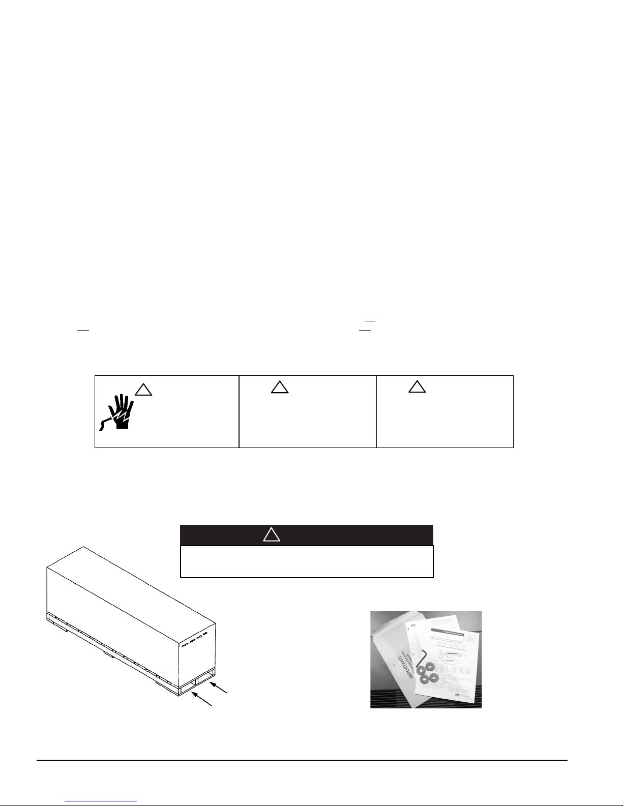
A forklift or other lifting device is needed to install this product. Applicable tools for lifting, hook-up of piping, electrical and insulation. Unit comes
with an allen wrench and four (4) lagging washers in the envelope in end compartment of the unit. (see photo below)
Install this product in accordance with good engineering practices and workmanship, following these general instructions, plus the job-specific
AAF®-HermanNelson®submittal drawings provided for specific dimensions, unit arrangements, controls and electrical details, pipe stub-up
locations, etc.
Pre-Installation Considerations
Storage – If equipment is stored for any length of time before installation, it should remain in its shipping packaging in a clean, dry, climate
controlled area.
Safety Information
Follow all safety codes. Wear safety glasses and work gloves. Use a quenching cloth for brazing operations. Have a fire extinguisher available. Follow all warnings and
cautions in these instructions and attached to the unit. Consult applicable local building codes and National Electrical Codes (NEC) for special requirements.
Recognize safety information. When you see a safety symbol on the unit or in these instructions, be alert to the potential for personal injury. Understand the meanings
of the words DANGER, WARNING, and CAUTION. DANGER identifies the most serious hazards that will result in death or severe personal injury; WARNING means
the hazards can result in death or severe personal injury; CAUTION identifies unsafe practices that can result in personal injury or product and property damage.
Improper installation, adjustment, service, maintenance, or use can cause explosion, fire, electrical shock, or other conditions which may result in personal injury or
property damage. This product must be installed only by personnel with the training, experience, skills, and applicable licensing that makes him/her “a qualified
professional HVACR installer.”
DISCONNECT ALL ELECTRICAL
POWERBEFORESERVICINGUNIT
TO PREVENT INJURY OR DEATH
DUE TO ELECTRICAL SHOCK.
WARNING
HAZARDOUS VOLTAGE!
DISCONNECT ALL ELECTRIC POWER IN-
CLUDING REMOTE DISCONNECTS BEFORE
SERVICING. FAILURE TO DISCONNECT
POWER BEFORE SERVICING CAN CAUSE
SEVERE PERSONAL INJURY OR DEATH.
!CAUTION
USE COPPER CONDUCTORS ONLY.
UNIT TERMINALS ARE NOT DESIGNED TO
ACCEPT OTHER TYPES OF CONDUCTORS.
FAILURE TO DO SO MAY CAUSE DAMAGE
TO THE EQUIPMENT.
!
Forklift lifting location
(see Caution above and table 2, page
11 for unit weights)
Shipping Envelope Contents - Located in
right end compartment of unit.
CAUTION
!
Use 72" length forklift tines, short tines will damage the unit
bottom.
!DANGER

IM 725 (1-02) 3
Figure 1 – Typical Classroom Unit Ventilator Installation And Louver Details (see installation section for typical warnings and cautions)
Figure 2 – Typical VentiMatic
™
Shutter Assembly Installation (see installation section for typical warnings and cautions)
Unit Gasket
Pipe Tunnel
Lag Screws (By Others)
Weep Holes
Caulk Top And
Two Sides Of Louver
Sealed Mortar Bed
Caulk
Weep
Holes
Floor
Unit Insulating Blanket
Back Of Unit
Unit Bottom Gasket
Seal Under Unit
Bird
Screen
Internal Column For
Wall Bracing
(By Others)
Caulk
(top and 2 Sides)
Louvers
Drain Holes
(Do Not Block)
Flange
(4 Sides)
1" Minimum
Lintels (By Others)
Bird Screen
Sealed Cement Mortar
Pitched Away from Unit
Toward Louver
Vertical or Horizontal Blade Wall Intake
Louver (Flanged)
(Vertical Blade Shown)
Drain Holes
(Do Not
Block With
Mortar or
Caulking
Materials
Bird Screen
Sealed Cement
Mortar Pitched
Away from Unit
Toward Louver
1" Minimum
Vertical or Horizontal Blade Wall Intake Louver
(Recessed Without Flange)
(Horizontal Blade Shown)
Lintels (By Others)
Louvers
Unit Gasket
Louver
Unit Ventilator
Outdoor Air Opening
Outside
Roomside
See figure 1 for typical louver installation
Outside
Roomside
VentiMatic Shutter
Unit Outside Air Opening
Wall Openings, Louvers, and VentiMatic Shutter
Prior to unit installation, be sure that the exterior wall openings and louvers, as applicable,
are ready and in accordance with the job plans.
Vertical Floor Models AVS, AVV, AVB, AVR are typically installed in front of a wall
opening containing a properly sized louver that is designed to let in outside air while
preventing water (such as driving rain) from getting past the louver and into the unit itself.
A weather-tight seal keeps unwanted air and moisture from entering the occupied space.
See Figures 1 through 18, and table 1 for various louver details.
Building Wall

4IM 725 (1-02)
Figure 3 – Horizontal and Vertical Blade Louvers, Without Flange
Figure 4 – Horizontal and Vertical Blade Louvers, Without Flanges With Grille or With Flange Without Grille
Louver drain lip
Grille/Louver with weep hole
Vertical Blade Louver
Horizontal Blade Louver
Flange
Flange
Outside Air
Outside Air
Outside Air
Bird Screen On Side Toward Unit
Vertical Louver with Flange,
without Grille
Horizontal Louver without
Flange, with Grille
CAUTION
!
Locate Weep Hole or Drain Lip at bottom of louver to allow
proper drainage.

IM 725 (1-02) 5
Figure 6 -165⁄8" (422mm) Deep Unit with Open Pipe Tunnel & High Louver
Application with Chased Wall
1"
(25mm)
Sealed Cement
Mortar;
Pitch Away
From Unit
Louver
Lintel
(By Others)
Floor Line
Piping
Louver
Not Less
Than 3" (76mm)
Not More
Than 21" (533mm)
Sealed Cement
Mortar;
Pitch Away
From Unit
Piping
Floor Line
Figure 5 - The 165/8” (422mm) Deep Unit with Open Pipe Tunnel and Standard
Louver Location
Louver Installation With Typical Unit Configurations
Unit Configuration Type AL
1"
(25mm)
Important: Gasket sealing
surface is required. (see figure
13 & 14 on page 7) Seal under
unit required.
Important: Gasket sealing
surface is required. (see figure
13 & 14 on page 7) Seal under
unit required.
Lintel
(By Others)
Figure 7 - Above Floor Level Outdoor Air Intake Using Arrangement AV or AL
With Accessory Closed Pipe Tunnel
Piping
Floor Line
Lintel (By Others)
Intake Louver
Not Less Than 3"
Not More
Than 28"
Insulated Closure
Plate Accessory
Provide
Drainage
1"
(25mm)
Important: Gasket sealing
surface is required. (see figure
13 & 14 on page 7) Seal under
unit required.
Figure 8 - Floor Level Outdoor Air Intake With Window Below Unit Top Using
Arrangement AL And 9˝ “Finished” (Painted) Accessory (Uninsulated) Closed
Pipe Tunnel
Unit Configuration Type AL
Lintel (By Others)
Intake Louver
Sealed Cement
Mortar;
Pitch Away
From Unit Sealed Cement
Mortar;
Pitch Away
From Unit
Important: Gasket sealing
surface is required. (see figure
13 & 14 on page 7) Seal under
unit required.
Sash Piping
1"
(25mm)
Painted Insulated Closure Plate Accessory
Floor Line
Provide
Drainage
Gasket Seal Gasket Seal
Gasket Seal
Accumulated moisture can cause property damage if not
properly drained. Installing contractor must provide such
drainage.
CAUTION
!

6IM 725 (1-02)
Figure 11 – The 217/8” (556mm) Deep Full Adapter Back Unit with Closed Pipe
Tunnel, Ducted with Top Intake
Figure 12 – 217/8" (556mm) Deep Partial Adapter Back Unit with Open Pipe
Tunnel
Intake Louver
Not More
Than 12"
Unit Configuration Type AP Unit Configuration Type AK
Figure 9 - 217⁄8" (556mm) Deep Full Adapter Back Unit With Standard Louver
Application
Figure 10 - 217⁄8" (556mm) Deep Full Adapter Back Unit with High Louver
Application
Not More
Than 28"
(711mm)
Floor
Line
Unit Configuration Type AN
1"
(25mm)
Sealed Cement
Mortar;
Pitch Away
From Unit
Louver
Piping
Important: Gasket sealing
surface is required. (see figure
13 & 14 on page 7) Seal under
unit required.
Lintel
(By Others)
Piping
Floor
Line
Sealed Cement
Mortar;
Pitch Away
From Unit
Important: Gasket sealing
surface is required. (see figure
13 & 14 on page 7) Seal under
unit required.
Louver
Lintel
(By Others)
Piping
Piping
Important: Gasket sealing surface is required.
(see figure 13 & 14 on page 7) Seal under unit
required.
1"
(25mm)
Floor Line
Piping
Piping
Sealed Cement
Mortar;
Pitch Away
From Unit
Important: Gasket sealing
surface is required. (see figure
13 & 14 on page 7) Seal under
unit required.
Louver Installation With Typical Unit Configurations
Lintel
(By Others)
Gasket Seal Gasket Seal
Floor Line
Gasket Seal
Gasket Seal
Intake Louver
Piping
Piping
Window Sash
“Goose Neck”
Insulated Duct (By Others)
Duct Collar (By AAF)
Note:
Arrangement AB with full metal back panel, similar to
configuration type AN. (Outside air opening to be cut and
sealed by others.)

IM 725 (1-02) 7
Installing Louvers
Typical Installation Methods
If the fresh air opening has not yet been made, see figures 5 through
12 for the recommended locations and the job-specific plans for the
exact location. Follow local codes.
Cut the wall opening so that it is slightly larger than the louver being
installed. For dimensions, see Table 1. If the opening is already there,
measure to be sure there is a minimum of 3/8" (9mm) clearance around
all sides. For masonry installations, a lintel must be installed above all
louvers.
In thick wall applications, the portion of the wall between the louver
and the unit is the outside air plenum. Line this plenum area with 3/8"
(9 mm) mortar or other suitable material. In some applications, the job
specifications require a metal sleeve connection between the louver
and the unit. If using such a sleeve, properly caulk it to ensure a
weather-tight seal. This is critical in preventing freeze-ups, cold
drafts, and air infiltration. Be sure the wall is smooth, square, and
provides a suitable mating surface.
See figure 13. Before setting the louver, construct a sloping, sealed
cement mortar base to drain unwanted moisture to the outside. Be sure
the mortar base is 1" (25mm) thick at the unit and tapers toward the
louver. The mortar at the unit also acts as a backing against which the
open cell gasket of the unit itself can seal. This is critical in preventing
water leaks and air leaks under the unit. Be sure the sealed cement
mortar base is smooth and flush with the interior wall.
If it is not possible to construct a sloping mortar base, then field-
supplied flashing is required. See figure 14. The flashing should
terminate flush with the exterior of the building. Place a bead of caulk
under the flashing to prevent moisture from wicking back to the unit.
Do not caulk the joint between the louver and the flashing. This joint
is designed to let unwanted moisture escape.
Personal injury hazard. Avoid contact with sharp edges.
See figures 5 through 12. Before setting the louver, be sure the drain
lip or weep holes are at the bottom, and the bird screen is towards the
unit. See figures 3 and 4. Place a heavy bead of caulk along the top and
the two vertical sides of the louver, leaving the bottom uncaulked so
that if moisture gets into the area between the louver and the unit, it can
drain to the outside, unrestricted.
If the louver is supplied with flanges, (see figure 4) place an additional
bead of caulk on the inside of the top and side flanges that come in
contact with the building facade. Do not caulk the bottom flange. Place
the louver in the opening and push it tight against the supplied
building, fastening it to the exterior of the building using fasteners (by
others) appropriate to the installation. Seal the top and sides with a
waterproof caulk to make it weather-tight. Do not caulk the bottom of
the louver; doing so might trap unwanted moisture behind the flange.
(See figure 16)
If the louver is supplied with no flanges, (see figure 3) place the louver
in the opening so that it is recessed a minimum 1/16" (2mm) beyond
the building facade or as directed in the architectural plans. If specified
in the plans, secure the louver in the wall using mechanical fasteners
(supplied by others) appropriate to the installation. (See figure 15 for
suggested fastening). With the louver solidly in place, run a bead of
caulk around the perimeter of the louver to seal it weather-tight. Do not
plug the weep holes (horizontal louver) or the drip line (vertical
louver). This might restrict the flow of unwanted moisture to the
outside (see figure 16)
See figure 14. If flashing was used instead of the sloping mortar base,
caulk the flashing where it meets the inside of the opening between the
louver and the unit. This helps prevent moisture from getting under the
flashing and into the room.
CAUTION
!
Louver
No
Caulk
Unit Gasket
Wall Unit
1" (25mm)
Floor
Caulk
(By
Others)
Flashing
(By
Others)
Figure 14 - Typical Louver Installation with Flashing
Unit Gasket
Sealed Cement
Mortar;
Pitch Away
From Unit
Floor
Wall
Unit
Louver
No
Caulk 1" (25mm)
Figure 13 - Typical Louver Installation with Sloping Sealed Cement Mortar
Base
Table 1 - Recommended Wall Openings For Wall Louvers (for figures 18 - 20)
Recommended Maximum Number of VentiMatic
Wall Openings VentiMatic Shutters Shutter(s)
BC
For Wall Louvers Which Can Be Mounted Air Capacity
On Standard Louver Maximum
Length Height 24" Shutter 36" Shutter cfm L/s
24" 27" 245⁄8"10
7⁄8"
(610) (659) (613) (267) 10500 236
36" 39" 365⁄8"10
7⁄8"
(914) (991) (918) (267) 01750 354
48" 51" 485⁄8"10
7⁄8"
(1219) (1295) (1222) (267) 201000 472
60" 63" 605⁄8"10
7⁄8"
(1524) (1600) (1527) (267) 111250 590
72" 75" 725⁄8"19
7⁄8"
(1829) (1905) (1832) (495) 021500 708

8IM 725 (1-02)
Caulk
(Top and 2 Sides)
Louvers
Drain Holes (Do Not Block)
Flange (4 Sides)
1" Minimum
Lintels (By Others)
Bird Screen
Sealed Cement
Mortar Pitched
Away from Unit
Toward Louver
Vertical or Horizontal Blade
Wall Intake Louver
(Flanged)
(Vertical Blade Shown)
Lintels (By Others)
Louvers
Drain Holes
(Do Not
Block With
Mortar or
Caulking
Materials
Bird Screen
Sealed Cement
Mortar Pitched
Away from Unit
Toward Louver
1" Minimum
Vertical or Horizontal Blade
Wall Intake Louver
(Recessed Without Flange)
(Horizontal Blade Shown)
Notes:
1. Horizontal blade wall louver shown. Vertical blade wall louver also available
with Ventimatic shutter.
2. Optional exterior grille matches unit ventilator wall louver in material and
design. Mounted on wall louvers.
3. Optional steel interior wall grille should be used to conceal the interior wall
opening whenever the Ventimatic shutter is not located behind shelf cabinets
or DraftStop enclosure. Hardware to mount the interior wall grille is not
included.
Installing the VentiMatic Shutter Assembly
The VentiMatic Shutter Assembly is mounted on an installed wall
louver. For larger units with 100% ventilation air dampers, two
VentiMatic Shutters may be mounted side by side on the same louver.
See figure 20.
The size and appearance of the wall louvers with or without optional
grilles used with the unit ventilator, and the VentiMatic Shutter, are
identical.
Figure 15 - Suggested method for fastening louver (without flange)
inside wall opening .
Figure 18 - Louver Details, Dimensions
As Directed
By Architect
3⁄4" (19mm) Approx.
7"
(178mm)
Cement Mortar
Steel Interior Wall Grille
(Optional) See Note 3
125⁄8"
(314mm)
3⁄4" (19mm) Approx.
Bird
Screen
Do Not Block Drain
Holes With Caulk or
Mortar
Not
Less
Than 9"
(229mm)
Cement Mortar
C
(see table 1, page 7)
Wall Opening
Louver
(Bird Screen Not Shown)
Angle Iron
(by others)
Room Side
Exterior
Figure 16 - Louver Installation Views
Note: Birdscreen and louver are shipped in one (1) piece.
Pre-Installation Considerations
VentiMatic™Shutter Assembly
In many installations, an AAF®-HermanNelson®VentiMatic Shutter
Assembly is specified. See figure 17. This one-way shutter is a
continuously variable, gravity actuated, room exhaust vent that operates
in direct response to positive static pressure. It opposes any airflow
into the room and allows a slight positive pressure.
It is important that the VentiMatic shutter and unit ventilator louvers
are mounted on the same wall. This neutralizes the effect of the wind.
Forcing excess air into the room through the unit ventilator louver
overcomes the same wind pressure that works to keep the VentiMatic
shutter closed. This prevents room air exhausting from the room
through the VentiMatic shutter.
Figure 17 – VentiMatic Shutter Assembly
Outside
Louver
VentiMatic Shutter
Roomside
Relief Air
When installing VentiMatic Shutter(s) on the wall louver, make sure
all moving parts are free to operate unobstructed and placed level and
plumb for proper operation. If optional steel interior wall grille is
furnished, install as shown in Figure 18.

IM 725 (1-02) 9
Plastic packaging is a suffocation hazard, dispose of properly.
Keep away from children.
Cleaning agents may cause serious damage to internal
components, such as aluminum coils and electronic controls,
etc. Do not operate unit ventilator while building maintenance
cleaning agents are in use.
Aluminum Wall Louver
Assembly with Bird Screen
(See Note 1)
3'' (76mm)
VentiMatic
Shutter
Assembly
Center Cover103⁄8"
(264mm)
Figure 20 - Two VentiMatic Shutters & Wall Louver
Aluminum Wall Louver
Assembly With Bird Screen
(See Note 1)
B
(see table 1,
page 7)
Steel
VentiMatic
Shutter
Assembly
41⁄8"
(105mm)
237⁄8" (606mm)
or
357⁄8" (911mm)
2" (51mm)
103⁄8"
(264mm)
3" (76mm)
Decorative Exterior Grille Also Available (See Note 2)
(Bird Screen not shown)
Figure 19 - Single VentiMatic Shutter & Wall Louver
B
(see table 1,
page 7)
Before Installing Unit Ventilator
Check that the lifting equipment can handle the weight of the
unit safely. Personal injury may result if proper lifting and
moving methods are not used. (See table 2, page 11 for
approximate shipping weights)
Personal injury hazard. Handle with care to avoid possible cuts
and abrasions from exposed edges. Avoid contact with sharp
edges.
Improper handling can damage internal components. Do not
stand the unit on end or stack.
This product was carefully packed and thoroughly inspected
before leaving the factory. Responsibility for its safe delivery
was assumed by the carrier upon acceptance of the shipment.
Claims for loss or damage sustained in transit must therefore
be made upon the carrier, as follows:
VISIBLE LOSS OR DAMAGE
Any external evidence of loss or damage must be noted on the
freight bill or carrier’s receipt, and signed by the carrier’s agent.
Failure to adequately describe such external evidence of loss
or damage may result in the carrier’s refusing to honor a
damage claim. The form required to file such a claim will be
supplied by the carrier.
CONCEALED LOSS OR DAMAGE
Concealed loss or damage means loss or damage which does
not become apparent until the product has been unpacked. The
contents may be damaged in transit due to rough handling even
though the carton may not show external damages. When the
damage is discovered upon unpacking, make a written request
for inspection by the carrier’s agent within fifteen (15) days of
the delivery date. File a claim with the carrier since such
damage is the carrier’s responsibility.
WARNING
!
CAUTION
!
CAUTION
!
NOTICE
WARNING
!
WARNING
!
Step 1
Uncrate and Inspect the Unit Ventilator(s)
Carefully remove the packaging, remaining alert to any signs of
shipping damage. Be careful not to discard components that may be
included with the packaging. (You may want to retain some or all of
the packaging to provide jobsite unit location information and
temporary protection for the unit ventilator after installation.) Be sure
to dispose of plastic packaging and protective cardboard properly, in
accordance with local recycling rules and guidelines.
If unit is damaged, file a claim with the carrier. Notify the local AAF®-
McQuay Unit Ventilator representative immediately.
Properly Identify Unit Ventilator(s)
To be sure the correct unit ventilator(s) is/are installed in the correct
location(s), the installer must check the packing list and unit
identification/tagging number(s) against the plans. Further, the unit
data plate, (see figure 21) located on the lower right end of the unit
ventilator, contains specific information of standard components as
follows: (see next page)
Installing The Unit Ventilator
Figure 21 - Unit Ventilator Data Plate and Serial Number Location
Outside
Outside
▲
▲
Decorative Exterior Grille Also Available (See Note 2)
(Bird Screen not shown)
Directions given in this bulletin
for right and left sides assume
a position facing the indoor side
of the unit ventilator
INFORMATION

10 IM 725 (1-02)
1. Product Category
U = Unit Ventilator
2. Product Identifier*
AVS = Floor, Face and Bypass Damper, Heat/Cool, Heat Only, Cool
Only
AVV = Floor, Valve Control, Hydronic or Electric Heat/Cool, Heat
Only, Cool Only
AVR = Floor, Valve Control, Hydronic or Electric Reheat/Dehumid
AVB = Floor, Face and Bypass Damper, Hydronic Reheat
* End panels not included; Ordered as accessory, shipped
separately boxed
3. Design Series
4 = D Design
4. Nominal Capacity, cubic feet per minute (cfm)
S07 = 750
S10 = 1000
S13 = 1250
S15 = 1500
5. Voltage, volts, phase, Hertz (v-Hz-ph)
A = 115-60-1
C = 208-60-1
G = 230-60-1
J = 265-60-1
D = 208-60-3
H = 230-60-3
K = 460-60-3
6. Cooling Options
U = 2-row Chilled Water/Hot Water, 2-pipe
D = 3-row Chilled Water/Hot Water, 2-pipe
E = 4-row Chilled Water/Hot Water, 2-pipe
F = 5-row Chilled Water/Hot Water, 2-pipe
1 = 2-row High Capacity Chilled Water/Hot Water, 2-pipe
2 = 3-row High Capacity Chilled Water/Hot Water, 2-pipe
3 = 4-row High Capacity Chilled Water/Hot Water, 2-pipe
4 = 5-row High Capacity Chilled Water/Hot Water, 2-pipe
G = Direct Expansion (DX)
S = 3-row Chilled Water
V = 2-row Chilled Water
W = 4-row Chilled Water
Y = 5-row Chilled Water
5 = 2-row High Capacity Chilled Water
6 = 3-row High Capacity Chilled Water
7 = 4-row High Capacity Chilled Water
8 = 5-row High Capacity Chilled Water
Z = None
7. Heating Options
00 = None
12 = Low Electric Heat, 3-element
13 = High Electric Heat, 6-element
65 = 1-row, Hot Water
66 = 2-row, Hot Water
67 = 3-row, Hot Water
68 = Low Capacity Steam
69 = High Capacity Steam
78 = Low Capacity Steam, Opposite End Drain
79 = High Capacity Steam, Opposite End Drain
Unit Ventilator (Floor Type) Data Plate - Specific Information
8. Hand Orientation [Right (RH) Left (LH)]
A = LH Both Coils (only w Controls by Others)
B = RH Both Coils (only w Controls by Others)
D = RH Electric Heating, One Coil
E = LH Heating, RH Cooling
F = RH Heating, LH Cooling
G = RH Electric Heating, LH Cooling
R = LH Single Coil
S = RH Single Coil
9. Controls
15 = MicroTech w Unit Mounted Sensor
16 = Part Load Variable Air MicroTech w Unit Mounted Sensor and
Humidity Sensor (if required)
19 = MicroTech for Remote Wall Sensor (accessory Sensor and
Humidity Sensor (required)
20 = Part Load Variable Air MicroTech for Remote Wall Sensor
(accessory Sensor/ Humidity Sensor required)
23 = Field Mounted Controls by Others
17 = Digital Ready/with Damper Acutators, (3)@ 10k NTC Sensors,
3 Terminal Strips, 75 VA 24 Volt T’fmr, w/o UV Controller
10. Discharge
AB = 21-7/8" Unit, Top Bar Grille Discharge, Full Adapter Back w
Closed Pipe Tunnel w Solid Back
AK = 21-7/8" Unit, Top Bar Grille Discharge, Partial Adapter Back w
Open Pipe Tunnel
AL = 16-5/8" Unit, Top Bar Grille Discharge
AM = 21-7/8" Unit, Top Bar Grille Discharge, 2" Stepdown Full
Adapter Back w Closed Pipe Tunnel
AN = 21-7/8" Unit, Top Bar Grille Discharge, Full Adapter Back w
Closed Pipe Tunnel
AP = 21-7/8" Unit, Top Bar Grille Discharge, Partial Adapter Back w
Closed Pipe Tunnel, Top Duct Intake
11. Return Air (RA) / Outside Air (OA)
22 = RA Bottom Front / OA Rear Duct Collar
24 = 100% RA Bottom Front / No OA Opening / No OA/RA Dampers
30 = RA Bottom Front w Draft Stop / OA Rear Duct Collar
12. Power Connection
G = Box w Switch
13. Color
B = Putty Beige
G = Soft Gray
I = Antique Ivory
W = Off White
14. SKU
B = Standard Delivery
C = Extended Delivery
15. Product Style
1
Field-Installed Accessories may accompany Unit Ventilator(s), or
may be shipped separately. These may include: Adapter Backs;
Aluminum Louvers; Aluminum Grilles; Auxiliary Drain Pans; Controls
/ Sensors; End Panels; Spare Filters; MicroTech Controls, Sensors
(temperature, humidity, CO2); End of Cycle DDC Valve; Modulating
DDC Valves; Subbases. See instructions shipped with accessories
and install according to these and the plans.
Field 12345 6789101112 13 14 15
Model UAVS 4 S07 A S 65 E 23 AL 22 G B C 1

IM 725 (1-02) 11
Models
AVS, AVV, Dimension "A"
AVR, AVB Inches (mm)
S07 48" (1219)
S10 60" (1524)
S13 72" (1828)
S15 84" (2133)
Models Shipping Weight Approx. Shipping Weight Filter Size Unit Length* Number
AVS, AVV, lbs. (kg) lbs. (kg) in. (mm) in. (mm) Of Fans
AVR, AVB 165/8"Units 217/8"Units
S07 350 (168) 370 (163) 10 x 36.5 x 1 62 (1575) 2
(254 x 927 x 25)
S10 425 (193) 445 (202) 10 x 48.5 x 1 74 (1880) 3
(254 x 1232 x 25)
S13 495 (225) 525 (238) 10 x 60.5 x 1 86 (2174) 4
(254 x 1551 x 25)
S15 570 (259) 600 (272) Two: 10 x 36.5 x 1 98 (2489) 4
(254 x 927 x 25)
Step 2
Position the Unit Ventilator
Move the unit ventilator to the correct location. See Table 2 for approximate shipping weights.
Carefully remove unit ventilator from wood skid. Be sure to properly dispose of the skid in accordance with local recycling rules and guidelines.
Table 2- Approximate Shipping Weights, Physical Data
* Measurement is without end panels. All unit ventilators are 30" (762 mm) high.
Figure 22 - Front View With End Panels - Mounting Holes Locations
Mounting Holes
Figure 23 - Rear View Without End Panels And Subbase - Piping And Electrical Knockout Locations And Dimensions
131⁄2"
(343mm)
7" (178mm)
22"
(559mm)
51⁄2"
(140mm)
11⁄2"
(38mm) 7"
(178mm)
5" (127mm)
4" (102mm)
27/8" (73mm)
8"
(203mm)
8"
(203mm)
Knockout Opening Between Pipe
Tunnel & End Compartment.
Rear Entry Area or Draftstop Opening Knockouts
30"
(762mm)
61⁄2" (165mm)
1" (25mm)
7" (178mm)
1" (25mm)
10"
(254mm)
231⁄2"
(597mm)
Outdoor Air Intake Opening
NOTICE
End compartment Draftstop knockouts
must be removed for proper Draftstop
operation. (21-7/8" units only)
A
(See Table 3)
IMPORTANT!
To prevent leakage of outdoor air that wastes energy, causes drafts and erratic unit ventilator operation, be sure to heed the following details:
At the correct unit ventilator location, examine the wall surface, making sure that it is smooth, plumb, and perpendicular to the floor, (See
Figure 1). The seals on the rear of the unit ventilator will take up the small irregularities found in normal masonry construction. If the wall is
irregular or has mullions, install furring strips to provide a flush surface against which the unit ventilator can seal. If there are moldings on
the floor/wall line, omit them behind the unit ventilator. Provide a sealing surface at the floor line. Install a seal pad under the unit to prevent
air leakage. Install the unit ventilator against a wall made of non-combustible material, and on a floor made of non-combustible material. Floor
must be level, unbroken and structurally strong to support the unit.
Table 3 - Dimension Between Mounting Holes
Note:
See Draftstop IM bulletin for suggested installation
procedure.

12 IM 725 (1-02)
Step 3
Make Piping Connections
Be sure the hot and chilled water supply and return system are
thoroughly flushed and cleaned before connecting piping to the
unit ventilator.
In All Systems
Be sure to install the control valve(s) on the correct unit ventilator.
Indiscriminate mixing of valves in the field can result in valves
improperly sized for the desired flow rate, which can result in poor
operation and coil freezeups. Install control valve so there is at least
2" (51mm) minimum clearance to remove the actuator from the valve
body.
Be certain that the control valve is installed correctly, with its
orientation vertical. Valves should be installed at least 5°off center.
Be certain that the control valves are installed with the proper
port orientation to provide proper flow and fail safe operation.
Incorrect installation can result in improper unit operation, and/
or the possibility of coil freeze-up.
With future servicing considerations in mind, use standard, field-
supplied shutoff valves and union connections; this permits easy
removal of the coil or control valve if servicing is required.
While brazing have an extinguisher readily available. Wear
appropriate eye and hand protection. Ensure all areas with
shared ventilation have ample fresh air ventilation.
Refer to figure 1 and figures 22 through 27 and attach the unit
ventilator to the wall through the four (4) mounting holes provided,
using field-supplied fasteners appropriate to the wall construction and
the washers provided in the brown envelope with these instructions
(figure 25). Envelope also contains allen wrench to provide access to
unit. Push the unit ventilator tight to the wall structure so that the
outdoor air seals are compressed. Secure the wall fasteners to prevent
the unit ventilator from moving and tipping over.
Remove moldings
behind unit
Before setting the unit ventilator in place, if it is a cooling unit, check
the condensate drain hand connection to be sure it is the same as the
cooling coil hand of connection, and that it agrees with the drain stub-
up. If necessary, move condensate drain cap to the opposite end. Do
not discard (see figure 24).
Before setting the unit ventilator in position, be sure that field-
supplied electrical connections are in place, de-energized and in
accordance with the plans.
Move the unit ventilator into position against the wall surface. Check
to see that the unit ventilator is level, from end to end and back to front.
Using a 4' level is recommended. Leveling bolts are located at each
end of the front kickplate (see figure 27).
Unit must be anchored to an internal wall column or other suitable
support (see figure 1, page 3)
11"
(279 mm)
7⁄8"22 mm)
O.D. Copper
Drain
7⁄8"(22 mm)
O.D. Copper
Drain
5"
(127 mm)
Condensate
Drain
Figure 24 - Move Condensate Drain Cap To Opposite End of Drain Stub-Up.
Left Hand
Front View of End Compartment
Right Hand
11"
(279 mm)
Figure 25 - Shipping Envelope Contents
Figure 26 - Setting The Unit Ventilator In Place
Figure 27 - Leveling Legs Location
DANGER
!
Disconnect all electrical power before servicing unit to prevent
injury or death due to electrical shock.
CAUTION
!
CAUTION
!
WARNING
!
CAUTION
!

IM 725 (1-02) 13
In Water Systems
After flushing piping adequately, so all debris is removed, fill the
system.
At initial operation, vent manually by unscrewing the vent plug one or
two turns, figure 31. After venting, tighten the vent plug firmly.
Unscrew the vent plug only one or two complete turns. System
is under pressure and can result in severe personal injury
WARNING
!
Figure 31 - Vent and Drain Plug
Unscrew the vent plug one or
two turns to manually vent
system.
Water system under pressure. When venting keep face and
body parts well away, and vent slowly.
Figure 28 - Hot Water Coil Connections
Chilled Water Coil
Hot Water Coil
Chilled Water Return
Chilled Water Supply
Hot Water Return
Hot Water Supply
Water Coil Connections
Hook up water piping in accordance with the below figure’s 28 and 29
for hot water and chilled water coil connections.
Figure 29 - Chilled Water Coil Connections
Failure to install water piping to coils properly can result in
improper unit operation and possible coil freeze-ups.
Proper ventilation is required for brazing. When brazing, be sure to
protect unit ventilator components from overheating damage (melting
insulation, also damage to valves, wiring, electronics, sensors, etc.).
Before filling, be sure to flush all piping adequately so that all debris
is removed. Foreign debris can prevent proper valve operation, resulting
in overheating, overcooling, etc.
Ensure proper insulation of supply and return piping. Proper insulation
prevents loss of unit ventilator capacity, overheating of end
compartment, and / or moisture dripping.
The piping to and from the unit must be protected from outside air and
freeze conditions. The piping must be suitably insulated for
condensation or heat lose or gain. Penetrations entering the unit end
compartments must be fitted/sealed for unit integrity.
Figure 30 - Protect Components From Overheating Before Brazing
Use A Quenching Cloth
When Brazing, to Prevent
Overheating The Piping
Components (Avoid Valve
Damage and Eratic
Operation)
Vent
Drain Plug
CAUTION
!
WARNING
!

14 IM 725 (1-02)
Heating Coils
00 = None
Cooling Coils
V=2Row CW Coil
S=3Row CW Coil W= 4Row CW Coil
Y=5Row CW Coil
5=2 Row High Capacity CW Coil
6=3 Row High Capacity CW Coil
Heating Only
Figure 32 - Hot Water Heating Only Unit
(Coils 65, 66, 67)
Cooling Only
Unit Series S07 S10 S13 S15
Suction Line O.D. (in/mm) 3⁄419 3⁄419 7⁄822 7⁄822
Liquid LIne O.D. (in/mm) 1⁄46.35 1⁄463⁄810 3⁄810
Notes:
1. All coils have same end supply and return connections.
2. Steam coils have a factory installed pressure equalizing valve and a 24" (610mm) long
pressure equalizing line which terminates in a 1⁄2" M.P.T. fitting.
3. Steam/hot water connections may be same end as cooling coil connections, but they
are recommended to be opposite end to facilitate piping. (Must be opposite end when
using AAF controls.)
4. Cooling condensate connection is shipped same end as cooling coil connections, but
is field reversible.
5. Electric heating coil power connections are right end only. Junction box has 1"(25mm)
and 2" (51mm) (trade size) knockouts, 101⁄2" (267mm) from right end of the unit.
6. For limitations with coil combinations see tables 151-1, 151-2, 152-1 and 153-1.
7. Coil stubs are 7⁄8" I.D. (female) and terminate 9" (229mm) from the end of the unit.
8. Steam coils are 11⁄8" female (sweat) connections and terminate 9” (229mm) from the
end of the unit.
9. DX coils (G) have O.D. sweat connections. Interconnecting tube by others. See table
7 for correct tubing size.
Table 6 - Dimensions
Table 7 - DX Coil (G) Connection Tubing
L.H. Connections
A
B
R
S
J115⁄8
(295 mm)
133⁄8
(340 mm) 133⁄8
(340 mm)
115⁄8
(295 mm)
S
R
A
B
J
S = Supply
R = Return
A
C
R
S
J73⁄8
(187 mm)
115⁄8
(295 mm) 115⁄8
(295 mm)
S
R
C
A
J
73⁄8
(187 mm)
Junction
Box
HJ
Electric Heating
Only
S = Supply
R = Return
R.H. Connections L.H. Connections R.H. Connections R.H. Connections
133⁄4
(349 mm)
Table 4 - Heating Only – Coil Position/Combinations In Air Stream
(one coil per position) Note: X indicates Available.
Face and Bypass Valve
First Position in Air Stream Second Position in Air Stream AVS AVV AVV Elec.
65 66 67 68 69 78 79 Z X X
12 13 Z X
Heating Coils
65 = 1 Row Hot Water Coil
66 = 2 Row Hot Water Coil
67 = 3 Row Hot Water Coil
68 = Low Capacity Steam Coil
69 = High Capacity Steam Coil
78 = Opposite End Drain Low Capacity Steam Coil
79 = Opposite End Drain High Capacity Steam Coil
12 = Low Electric Heat Coil
13 = High Electric Heat Coil
Cooling Coils
Z=None
Table 5 - Cooling Only – Coil Position/Combinations In Air Stream
(one coil per position) Note: X indicates Available.
Face and Bypass Valve
First Position in Air Stream Second Position in Air Stream AVS AVV
VSWY 00 XX
5678
G00 X
7=4 Row High Capacity CW Coil
8=5 Row High Capacity CW Coil
G= Direct Expansion Coil
L.H. Connections
A
B
S
R
J115⁄8
(295 mm)
133⁄8
(340 mm) 133⁄8
(340 mm)
115⁄8
(295 mm)
R
S
A
B
J
B
D
LL
SL
J113⁄8
(289 mm)
133⁄8
(340 mm) 113⁄8
(289 mm)
C
D
J
73⁄8
(187 mm)
SL
LL
S=Supply
R=Return
Figure 35 - Chilled Water Only Unit
(Coils S, W, Y, V, 5, 6, 7, 8) Figure 36 - Direct Expansion Cooling Only Unit (Coil G)
R.H. Connections L.H. Connections R.H. Connections
LL = Liquid Line
SL = Suction Line
Air Flow Air Flow
Air
Flow Air
Flow
Air Flow
Air Flow Air Flow Air Flow Air Flow
Unit Dimensions
Depth ABCDEFGHJ
in 165⁄863⁄8105⁄845⁄865⁄848
3⁄821⁄414 27⁄8
mm 422 162 270 117 168 102 213 57 356 73
in 217⁄8115⁄8157⁄897⁄8117⁄891⁄4135⁄871⁄2191⁄481⁄8
mm 556 295 403 251 302 235 346 191 489 206
Note: For opposite end drain steam coils (code 78,79) Return (R) is 71⁄4"(184mm) from bottom of unit and C - 27⁄8"(73mm) from back of unit.
Figure 33 - Steam Heating Only Unit
(Coils 68, 69, 78, 79)
Figure 34 - Electric Heating Only Unit
(Coils 12, 13)
Coil Headers, Locations

IM 725 (1-02) 15
Heat/Cool
See Notes and Tables 6 and 7 on page 14
Table 8 - Heat/Cool Position/Combinations In Air Stream (one coil per position) Note: X indicates Available.
Face and Bypass Valve
First Position in Air Stream Second Position in Air Stream AVS AVS Elec. AVV AVV Elec.
UDE F 00 X X
1234
65 66 67 68 69 78 79 V S 5 6 X X
65 66 W 7 X X
G65666768697879 X X
G1213 X
12 13 V S W 5 6 7 X
VSW567 12 X
Heating Coils
65 = 1 Row Hot Water Coil
66 = 2 Row Hot Water Coil
67 = 3 Row Hot Water Coil
68 = Low Capacity Steam Coil
Cooling Coils
U=2Row CW/HW 2-Pipe Coil
D=3Row CW/HW 2-Pipe Coil
E=4Row CW/HW 2-Pipe Coil
F=5Row CW/HW 2-Pipe Coil
1=2 Row High Capacity CW/HW 2-Pipe Coil
2=3 Row High Capacity CW/HW 2-Pipe Coil
3=4 Row High Capacity CW/HW 2-Pipe Coil
4=5 Row High Capacity CW/HW 2-Pipe Coil
V=2Row CW Coil
S=3Row CW Coil
W= 4Row CW Coil
5=2 Row High Capacity CW Coil
6=3 Row High Capacity CW Coil
7=4 Row High Capacity CW Coil
G= Direct Expansion Coil
69 = High Capacity Steam Coil
78 = Opposite End Drain Low Capacity Steam Coil
79 = Opposite End Drain High Capacity Steam Coil
12 = Low Electric Heat Coil
13 = High Electric Heat Coil
00 = None
L.H. Connections
A
B
S
R
J115⁄8
(295 mm)
133⁄8
(340 mm) 133⁄8
(340 mm)
115⁄8
(295 mm)
R
S
A
B
J
E
F
R
S
J
137⁄8
(352 mm)
155⁄8
(397 mm) 133⁄8
(340 mm) 115⁄8
(295 mm)
R
S
A
B
J
HWCoil
CWCoil
E
F
S
R
J
115⁄8
(295 mm) 73⁄8
(187 mm)
R
S
C
A
J
Steam
CWCoil
D
B
J113⁄8
(289 mm)
133⁄8
(340 mm)
R
SE
F
J
HWCoil
137⁄8
(352 mm)
155⁄8
(397 mm)
R
S
G
E
J
95⁄8
(244 mm)
137⁄8
(352 mm)
Junction
Box
HJ
Figure 37 - Chilled/Hot Water (2-pipe) Unit
(Coils D, E, F, U, 1, 2, 3, 4)
Figure 38 - Chilled Water and Hot Water Unit
Cooling Coils S, W, V, 5, 6, 7 Heating Coils 65, 66, 67
Figure 39 - Chilled Water and Steam Unit
Cooling Coils S, W, V, 5, 6, 7
Heating Coils 68, 69, 78, 79
Figure 40 - Direct Expansion (G) and Hot Water Unit
Cooling Coil G Heating Coils 65, 66, 67
Figure 41 - Direct Expansion (G) and Steam Unit
Cooling Coil G Heating Coils 68, 69, 78, 79
Figure 42 - Direct Expansion and Electric Heating
Cooling Coils G Heating Coils 12, 13
S = Supply
R = Return
S = Supply
R = Return S = Supply
R = Return
R.H. Connections L.H. Connections R.H. Connections L.H. Connections R.H. Connections
S=Supply
R=Return
LL = Liquid Line
SL = Suction Line
Heating Dimensions Shown
R.H. Connections R.H. Connections
Cooling Dimensions Shown Heating Dimensions Shown
137⁄8
(352 mm)
155⁄8
(397 mm)
LL
SL
D
B
J113⁄8
(289 mm)
133⁄8
(340 mm)
Steam
LL
SL
133⁄4
(349 mm)
D
C113⁄8
(289 mm)
73⁄8
(187mm)
Air Flow Air Flow
Air
Flow
Air Flow
Air
Flow Air
Flow
Air Flow
Air
Flow
Air Flow
Air
Flow
Air
Flow
Cooling Dimensions Shown Heating Dimensions Shown
S=Supply
R=Return
LL = Liquid Line
SL = Suction Line
LL
SL
LL SL
C
73⁄8
(187 mm)
C
LL
SL
73⁄8
(187 mm)
Junction
Box
HJ
Figure 44 - Chilled Water (2nd Position) and Electric Heating
Cooling Coils V, S, W, 5, 6, 7 Heating Coils 12,13
R.H. Connections
133⁄4
(349 mm) 137⁄8
(352 mm)
155⁄8
(397 mm)
R
S
Air Flow
HJ
Figure 43 - Chilled Water (1st Position) and Electric Heating
Cooling Coils V, S, W, 5, 6, 7 Heating Coils 12,13
R.H. Connections
133⁄4
(349 mm)
Junction
Box
Air Flow
133⁄8
(340 mm)
115⁄8
(295 mm)
RS
BA
Cooling Dimensions Shown
L.H. Connections Heating Dimensions Shown
R.H. Connections
Cooling Dimensions Shown
L.H. Connections
Note: For opposite end drain steam coils (code 78,79) Return (R) is 71⁄4" (184mm) from bottom of unit and C - 27⁄8" (73mm) from back of unit.
Coil Headers, Locations (Continued)

16 IM 725 (1-02)
Face and Bypass Valve
First Position in Air Stream Second Position in Air Stream AVB AVR AVR Elec.
VS56 6566 67 68 69 78 79 X X
W7 6566 X X
G65666768697879 X
G1213 X
VSW567 1213 X
Reheat
Table 9 - Reheat Coil Position/Combinations In Air Stream (one coil per position) Note: X indicates Available.
Heating Coils
65 = 1 Row Hot Water Coil
66 = 2 Row Hot Water Coil
Cooling Coils
V=2Row CW Coil
S=3Row CW Coil
W= 4Row CW Coil
5=2 Row High Capacity CW Coil
6=3 Row High Capacity CW Coil
7=4 Row High Capacity CW Coil
G= Direct Expansion Coil
67 = 3 Row Hot Water Coil
68 = Low Capacity Steam Coil
69 = High Capacity Steam Coil
78 = Opposite End Drain Low Capacity Steam Coil
79 = Opposite End Drain High Capacity Steam Coil
12 = Low Electric Heat Coil
13 = High Electric Heat Coil
Figure 48 - Direct Expansion (G) and Hot Water Unit
Cooling Coil G Heating Coils 65, 66, 67
Figure 49 - Direct Expansion (G) and Steam Unit
Cooling Coil G Heating Coils 68, 69, 78, 79
Figure 45 - Chilled Water and Hot Water Unit
Cooling Coils S, W, V, 5, 6, 7 Heating Coils 65, 66, 67
Figure 46 - Chilled Water and Steam Unit
Cooling Coils S, W, V, 5, 6, 7 Heating Coils 68, 69,
78, 79
Figure 47 - Chilled Water and Electric Heating
Cooling Coils V, S, W, 5, 6, 7
Heating Coils 12, 13
L.H. Connections
A
B
S
R
J
115⁄8
(295 mm)
133⁄8
(340 mm) 155⁄8
(397mm)
137⁄8
(352 mm)
R
SE
F
J
137⁄8
(352 mm)
95⁄8
(244 mm)
R
SG
E
J
Figure 50 - Direct Expansion and Electric Heating
Cooling Coils G Heating Coils 12, 13
S = Supply
R = Return
S = Supply
R = Return
R.H. Connections R.H. Connections
CWCoil
HWCoil
L.H. Connections
CWCoil
Air Flow
Air
Flow Air
Flow
Cooling Dimensions Shown Heating Dimensions Shown Cooling Dimensions Shown Heating Dimensions Shown
D
B
J113⁄8
(289 mm)
133⁄8
(340 mm)
R
SE
F
J
HWCoil
137⁄8
(352 mm)
155⁄8
(397 mm)
R
S
G
E
J
95⁄8
(244 mm)
137⁄8
(352 mm)
S=Supply
R=Return
LL = Liquid Line
SL = Suction Line
LL
SL
D
B
J113⁄8
(289 mm)
133⁄8
(340 mm)
Steam
LL
SL
Air Flow
Air
Flow
Air Flow
Air
Flow
S=Supply
R=Return
LL = Liquid Line
SL = Suction Line
LL SL
C
73⁄8
(187 mm)
C
LL
SL
73⁄8
(187 mm)
Junction
Box
HJ
R.H. Connections
133⁄4
(349 mm)
D
C113⁄8
(289 mm)
73⁄8
(187mm)
Air
Flow
LL
SL
HJ
R.H. Connections
133⁄4
(349 mm)
Junction
Box
Air Flow
133⁄8
(340 mm)
115⁄8
(295 mm)
RS
BA
Heating Dimensions Shown
R.H. Connections
Cooling Dimensions Shown
L.H. Connections Heating Dimensions Shown
R.H. Connections
Cooling Dimensions Shown
L.H. Connections
A
B
S
R
J
115⁄8
(295 mm)
133⁄8
(340 mm)
Steam
Air Flow
Note: For opposite end drain steam coils (code 78,79) Return (R) is 71⁄4˝ (184mm) from bottom of unit and C - 27⁄8˝ (73mm) from back of unit.
Coil Headers, Locations (Continued)

IM 725 (1-02) 17
Valves and Piping
The optional factory-supplied AAF®-HermanNelson®Control Valve(s)
for water applications can be either 2-way or 3-way type, and is / are
shipped separate from the unit ventilator itself so no shipping damage
occurs to the piping of the connection stub from the weight of the valve
and to provide the installer with maximum flexibility in making the
field piping connection. Before proceeding, see figures 53 through 62
as applicable, as well as the job-specific piping drawings.
Face and Bypass
2-Way and 3-Way End-of-Cycle Valves
Control 2 Position
Electrical 24 VAC, 50/60 Hz
Stroke Power Stroke 9 to 11 seconds
Spring return 4 to 5 seconds
Ambient 32°F to 125°F (0°C to 52°C)
Connections 3⁄4" FNPT
Static Pressure 300 psi (2100 kPa)
Close-Off Pressure 13 psi (90 kPa)
Temperature 32°F to 200°F (0°C to 93°C)
Connections 3⁄4" FNPT, 1" FNPT
Static Pressure 300 psi (2100 kPa)
Close-Off Pressure 13 psi and 15 psi
(90 kPa and 103 kPa)
Temperature 32°F to 200°F (0°C to 93°C)
Control 2 Position
Electrical 24 VAC, 50/60 Hz
Stroke Power Stroke 9 to 11 seconds
Spring return 4 to 5 seconds
Ambient 32°F to 125°F (0°C to 52°C)
Table 10 - 2-way Actuator
Table 11 - 2-way Valve Body
Table 12 - 3-way Actuator
Table 13 - 3-way Valve Body
Connection CvXY Z
3⁄4"(19mm) FNPT 7.0 111⁄16" (43mm) 11⁄16" (23mm) 35⁄8" (92mm)
*1"(25mm) FNPT 7.0 17⁄8" (47mm) 1" (25mm) 311⁄16" (94mm)
* 1" valve for steam only
Table 14 - EOC Connection
23⁄8"
(61mm)
33⁄16"
(81mm)
17⁄16"
(37mm)
35⁄8"
(92mm)
111⁄16"
(43mm)
111⁄16"
(43mm)
311⁄16"
(94mm) 31⁄4"
(83mm)11⁄4"
(32mm)
29⁄16"
(66mm)
3⁄4"
(19mm)
7⁄8"
(22mm)
Figure 52 - 3-way EOC Valve
3⁄4"
(19mm)
11⁄4"
(32mm)
31⁄4"
(83mm)
23⁄8"
(61mm)
33⁄16"
(81mm)
XX
Y
Z
311⁄16"
(94mm) 29⁄16"
(66mm)
3⁄4"
(19mm)
3⁄4"
(19mm)
7⁄8"
(22mm)
Figure 51 - 2-way EOC Valve
Notes:
1. See label furnished on 2-way valve to determine direction of flow through the
valve.
2. Adhere to the port orientation shown for the 3-way valve.
For hot water applications and chilled water/hot water (2-pipe) applications, the
2-way valve furnished is normally piped open to the coil; the 3-way valve is piped
normally open to the coil.
For chilled water applications, the 2-way valve furnished is normally piped closed
to the coil; the 3-way valve is piped normally closed to the coil.
All water coil stubs are 7/8" I.D. female sweat. Coil connections terminate 9"
(229mm) from the end of the unit. Hot water connections may be same end as
cooling coil connections, but are recommended to be opposite end to facilitate
piping. When using AAF®MicroTech controls, they must be opposite end.
The 2-way EOC hot water or 2-pipe CW/HW valve is furnished
normally open to the coil. When the valve is de-energized (off) there
is full flow through the coil. Energizing the valve shuts off the water
flow.
Figure 53 - 2-way EOC, Normally Open, Hot Water or 2-pipe CW/HW Valve Piping
The 3-way hot water or 2-pipe CW/HW valve is furnished normally
open to the coil. When the valve is de-energized (off) there is full flow
through the coil. Energizing the valve allows the water to bypass the
coil.
Figure 54- 3-way EOC, Normally Open, Hot Water or 2-pipe CW/HW Valve Piping
Return
Return
Balancing and Shutoff Valve
Shutoff Valve
Supply
Supply
2-way EOC
Valve Unit Coil
Unions
AB
Return
Return
Shutoff Valve
Shutoff Valve
Supply
Supply
3-way EOC Valve
Unit Coil
Union
Balancing
Valve
Bypass
A
B
AB Union
Heating – Hot Water End of Cycle Valve Piping

18 IM 725 (1-02)
Figure 59 - 2-way Modulating, Normally Open, Hot Water or 2-pipe CW/HW
Valve Piping
31⁄4"
(83mm)
6.9 Max.
(175mm)
Z
Y
X
Optional Factory-Supplied
2-way Modulating Valve Optional Factory-Supplied
3-way Modulating Valve
31⁄4"
(83mm)
6.9 Max.
(175mm)
Z
Y
X
Connection CvXY Z
1⁄2"(13mm) 1.3 3.02" 1.06" 8.02"
FNPT 2.2 (77mm) (27mm) (204mm)
4.4
3⁄4"(19mm) 5.5 3.60" 1.06" 8.02"
FNPT 7.5 (91mm) (27mm) (204mm)
*1"(25mm) 10.0 4.60" 1.13" 8.70"
FNPT 14.0 (117mm) (25mm) (221mm)
* 1" valve for steam only
Connection CvXY Z
3⁄4"(13mm) 2.0 3.0" 1.37" 8.02"
FNPT 4.0 (76mm) (36mm) (204mm)
3⁄4"(19mm) 6.8 3.60" 1.30" 8.02"
FNPT (91mm) (33mm) (204mm)
Table 15 - 2-Way Connection
Table 16 - 3-way Connection
Figure 57 - 2-Way Modulating Valve Figure 58 - 3-Way Modulating Valve
2-Way and 3-Way Modulating Valves
The 2-way EOC CW valve is furnished normally closed to the coil.
When the valve is de-energized (off) there is no flow through the coil.
Energizing the valve allows flow through the coil.
The 3-way EOC CW valve is furnished normally closed to the coil.
When the valve is de-energized (off) the flow bypasses the coil.
Energizing the valve allows flow through the coil.
Figure 55 - 2-way EOC, Normally Closed, Chilled Water Valve Piping Figure 56 - 3-way EOC, Normally Closed, Chilled Water Valve Piping
Return
Return
Balancing and Shutoff Valve
Shutoff Valve
Supply
Supply
2-way EOC
Valve Unit Coil
Unions
AB
Return
Return
Shutoff Valve
Supply
Unit Coil
Union
Shutoff Valve
Supply
3-way EOC Valve Union
Bypass
AB
AB
Balancing
Valve
Cooling – Chilled Water EOC Valve Piping
Heating – Hot Water Modulating Valve Piping
The 2-way Modulating hot water (2-pipe CW/HW) valve is furnished
normally open to the coil. When the valve is de-energized (off) there
is full flow through the coil. Energizing the valve reduces the volume
of water flow in a modulating fashion.
Return
Return
Balancing and Shutoff Valve
Shutoff Valve
Supply
Supply
2-Way
Modulating Valve Unit Coil
Unions
AB
The 3-way Modulating hot water or 2-pipe CW/HW valve is furnished
normally open to the coil. When the valve is de-energized (off) there
is full flow through the coil. Energizing the valve allows a varying
amount of water to bypass the coil.
Figure 60 - 3-way Modulating, Normally Open, Hot Water or 2-pipe CW/HW Valve
Piping
Return
Return
Shutoff Valve
Shutoff Valve
Supply
Supply
3-way Modulating Valve
Unit Coil
Union
Union
Balancing Valve
B
ABA
A
CAUTION
!
Care must be taken with modulating valves to ensure proper
water flow. In freezing conditions, water flow must be maintained
through the heating coil or a suitable freeze-prevention solution
employed to prevent freeze-up. Similarly, the cooling coil
should be drained or a suitable freeze-prevention solution
employed.

IM 725 (1-02) 19
In Steam Systems:
Theoptional factory-suppliedAAF®-HermanNelson®Modulating
Control Valve for steam applications is the 2-way type. It is shipped
separately from the unit ventilator to preclude shipping damage, yet
provide the installer with maximum flexibility in making the field
piping connection. Before proceeding, see Figure 63, as well as the
job-specific piping drawings.
Return
Shutoff Valve
Shutoff Valve
Supply
Return
Supply
Unit Coil
Equalizing Line
(Note 1)
Steam Trap
See Figures 64 and 65. Connect the 1/4" (6.35mm) vacuum breaker
tube to the downstream return line. Make this connection downstream
of the trap outlet.
Figure 63 - Typical 2-Way Modulating Valve, Steam Piping
Note: See label furnished on 2-way valve to determine direction of flow
through the valve.
For steam applications, the 2-way, angle pattern valve furnished is
normally piped open to the coil. All steam coils are 1-1/8" (34mm)
female sweat connections. Coil connections terminate 9" (229mm)
from the end of the unit.
Steam coils have a factory-installed pressure equalizing valve and a
24" (610mm) long pressure equalizing line that terminates in a 1/2"
M.P.T. fitting.
Steam connections may be same end as cooling coil connections, but
are recommended to be opposite end to facilitate piping. When using
AAF®MicroTech controls, they must be opposite end.
Figure 64 - Same End Connections (68/69 Coils)
Control Valve: Install On
Center Coil Connection
Vacuum Breaker
(By AAF-HermanNelson)
Vacuum Breaker Tube
(By AAF-HermanNelson)
Steam Trap (By Others)
1⁄4˝ Flare By 1⁄2˝ MPT
Half-Union And 1⁄4˝ Flare
(By AAF-HermanNelson)
Tee (By Others)
Cooling – Chilled Water Modulating Valve Piping
Figure 62 - 3-way Modulating, Normally Closed, Chilled Water Valve Piping
The 2-way Modulating chilled water valve is furnished normally
closed to the coil. When the valve is de-energized (off) there is no flow
through the coil. Energizing the valve allows flow through the coil in
a modulating fashion.
The 3-way Modulating chilled water valve is furnished normally
closed to the coil. When the valve is de-energized (off) the flow
bypasses the coil. Energizing the valve allows flow through the coil in
a modulating fashion.
Figure 61 - 2-way Modulating, Normally Closed, Chilled Water Valve Piping
Return
Return
Balancing and Shutoff Valve
Shutoff Valve
Supply
Supply
2-Way
Modulating Valve Unit Coil
Unions
A
AB
End of Cycle Steam Valve Piping
Return
Shutoff Valve
Supply
Supply
3-way
Modulating Valve
Union
Balancing Valve
A
B
Return
Shutoff Valve
Unit Coil
Union
AB

20 IM 725 (1-02)
Typical Hot Water Coil Piping
Figure 65 - Face and Bypass With End-of-Cycle Valve
(Piping Within Unit End Compartment)
Figure 66 - Face and Bypass With End-of-Cycle Valve
(Piping Outside Unit End Compartment)
Figure 67 - 3-Way Modulating Valve Control
(Piping Within Unit End Compartment)
Figure 68 - 3-Way Modulating Valve Control
(Piping Outside Unit End Compartment)
11
2
1
3
45
15
67
15
2
3
4
5
67
8
2
3
4
5
6
7
8
2
3
4
5
6
7
15
15
15
15
15
11
1
15
Coil Piping
Heating valve actuators should be mounted in an upright position
above the centerline of the valve body and should be piped normally
open to the coil. Modulating valve actuators for hot water applications
may be positioned above the valve body a maximum of 75°from the
vertical. For steam applications only, mount the modulating valve
actuator above the valve body at 45°from the vertical. Two-position,
end-of-cycle (EOC) valves used with face and bypass damper controlled
units may be positioned above the valve body a maximum of 85°from
the vertical. All control valves are shipped loose so no shipping
damage occurs to the piping or the coil connection stub from the
weight of the valve and to provide the installing contractor with
maximum flexibility in making the field piping connections. Refer to
AAF-HermanNelson factory instruction sheet shipped with the unit
for port orientation and a piping schematic. Control valves must be
installed on the units in which they are shipped. Indiscriminate mixing
of valves among units can result in valves not properly sized for the
desired flow rate. Control valves should be installed so that there is 2"
minimum clearance to remove the actuator from the valve body. As a
future service consideration, provide unions for removal of the unit
coil and/or the control valve.
Descriptions
Three-way control valve (AAF-HermanNelson)
Coil air vent (AAF-HermanNelson)
Coil drain (AAF-HermanNelson)
Shutoff valve (Others)
Balancing shutoff valve(s) (Others)
Supply
Return
Unions (Others)—Must disconect below floor line
2
1
3
6
4
5
7
815
14
13
12
11
10
9Two-way, two-posiiton valve (AAF-HermanNelson)
Union: Half attached to coil, half attached to valve
Modulating control valve (AAF-HermanNelson)
All piping, fittings and unions by others (not AAF-HermanNelson) except as
noted
Check valve and pressure equalizing line (AAF-HermanNelson)
Float and thermostaic steam trap (Others)
Supply and return coil connection and stub-up unions by others
Table of contents
Other AAF Ventilation Hood manuals