Eriez X8 User manual

X8 METAL DETECTOR
REFERENCE GUIDE
2023810A (sw pkg 1.0.0)

Use this product only in the manner described in this manual. If the
equipment is used in a manner not specified by the manufacturer,
the protection provided by the equipment may be impaired.
CAUTION
The metal detector is heavy. Do not lift nor support the metal
detector by hand/manually.
To avoid damage or injury, use only the handling and installation
procedures outlined in this reference guide.
CAUTION
Hazardous voltages are present in this equipment when energized.
All power sources must be isolated or disconnected before
accessing the inside of the enclosure.
Failure to follow these precautions may result in serious injury or
death.
WARNING - HAZARDOUS VOLTAGE
If you have a pacemaker or other implanted medical device, please
consult your doctor before using this product. Electromagnetic
waves can interfere with the operation of your pacemaker or other
medical devices.
CAUTION
Metal detectors emit electromagnetic fields, which may interfere
with some pacemakers or other implanted medical devices. The end
user bears the responsibility to determine if the emitted
electromagnetic fields will affect employees with medical devices. If
you have an implanted medical device, please consult your doctor
before being in the vicinity of the metal detector during operation.
CAUTION
1

To avoid injury or damage to the equipment, only qualified service
technicians are to install the metal detector at customer sites in
accordance with local safety codes.
CAUTION
To avoid injury or damage to the equipment, all electrical
installations are to be performed by qualified and competent
personnel authorized by Eriez Manufacturing Company. All electrical
installations are to be in compliance with local safety codes. Ensure
that all materials used in the installation of the equipment are
suitable and appropriate for purpose.
CAUTION
For continued compliance with electrical safety standards, the
protective earth connection from the power source must be
connected directly to the protective terminal on the wall of the
enclosure. This is required to be the FIRST connection to the
terminal, and secured with a star lock washer and nut, independent
of any other connections to the terminal.
CAUTION
An external disconnect switch labeled “Metal Detector” must be
installed near the metal detector to allow the metal detector to be
completely disconnected from the power source during installation
and maintenance. All lock-out tag-out procedures and local safety
codes are to be followed during metal detector installation and
maintenance.
The metal detector must not be positioned in a way that makes it
difficult to operate the disconnect switch.
CAUTION
2

Cleaning procedures may cause false trips of the metal detector,
resulting in actuation of any connected reject devices. Ensure
personnel and equipment are clear from the path of the reject
devices at all times. To avoid an unsafe condition or damage to
equipment, remove all power sources (including air supplies) from
the metal detector and reject devices prior to wash down.
CAUTION
To avoid injury or damage to the equipment, all electrical
maintenance on the metal detector is to be performed by qualified
and competent service technicians authorized by Eriez
Manufacturing Company.
CAUTION
The X8 metal detector is not designed nor intended for operation in
environments classified as hazardous locations/zones. Do not
operate the X8 metal detector in areas where the possibility of
explosions or fires exists.
CAUTION
For installations where the metal detector control screen presents
ergonomic challenges or unsafe viewing conditions, it is
recommended that a remote display be used to eliminate these
issues.
CAUTION
The metal detector will start automatically when power is restored
after a power interruption. All external components controlled by
relays within the metal detector control will also complete their
cycle when the metal detector is re-energized. The end user must
determine if a hazard exists and install the proper safety precautions
and protocol to ensure that an injury does not occur in the event of
a power interruption.
CAUTION
3

When cleaning the metal detector surfaces, use appropriate personal
protective equipment (PPE) for any physical/chemical/biological
hazards that may exist due to the end user’s production
environment. Avoid contact with contaminants on or around the
metal detector. Pressure Wash and sanitize metal detector surfaces
when maintenance is required.
CAUTION
EXPLANATION OF SYMBOLS
Cautionary information
Protective Conductor Terminal
Hazardous Voltage –Risk of Electric Shock
Pacemaker warning information
Pinch Point
4

Pg.7
Pg.9
Pg.13
Pg.23
Pg.34
Pg.88
Handling
Basic lifting and moving instructions
Specifications
Basic product specifications and safety information
Mechanical
Mechanical installation instructions
Electrical
Electrical Installation Instructions
User Interface
Every screen explained and easy to use how-to guides.
Maintenance
Maintenance and cleaning
Vertical Metal Detector
with Valve Addendum
Handling, installation and maintenance
Pg.90
5

6

HANDLING
RF INTERFERENCE
Radio Frequency (RF) emissions have been tested to the requirements of FCC 47CFR
Part 15B, FCC 47CFR Part 18, and CISPR 11/EN 55011 (Class A, Group 1). The Eriez
X8 Metal Detector generates an electromagnetic field, which has the potential to
escape. This field may interfere with nearby radio frequency equipment.
If interference becomes a problem, you may need to:
1. Move the Metal Detector or interfering equipment
2. Change the frequency on the Metal Detector
3. Call the Factory for further assistance
HANDLING INSTRUCTIONS
DO NOT LIFT THE METAL DETECTOR BY INSERTING ANYTHING INTO OR
THROUGH THE TUNNEL.
The inner surface of the tunnel protects the precisely tuned electronic circuit and
internal parts. The tunnel liner also protects the internal parts against water damage.
The integrity of this liner and seal must be maintained. Any damage or distortion to this
surface caused by handling will invalidate the warranty.
When handling, keep the metal detector on the shipping pallet as long as possible.
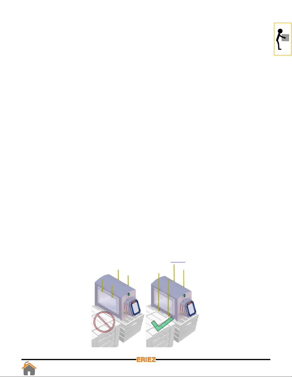
WHEN REMOVING THE DETECTOR FROM THE SHIPPING PALLET, LIFT ONLY ON
THE DETECTOR HOUSING SURFACES OR SUPPORTING FEET. DO NOT LIFT BY
THE CONTROL HOUSING THAT PROTRUDES FROM THE BODY OF THE METAL
DETECTOR.
If possible, lift the metal detector by using a crane and soft nylon slings running under
the entire metal detector housing as seen below. See Vertical Metal Detector with
Valve Addendum at the end of this reference guide Pg.90 for information concerning
vertical metal detectors.
7
Figure 1: Metal detector handling instructions

Larger metal detectors may have eyebolts preinstalled at the factory. When handling
with the eyebolts ensure loads are never applied perpendicular to the shank of the
eyebolts; they will break.
The metal detector is heavy. Do not lift nor support the metal
detector by hand.
To avoid damage or injury, use only the handling and installation
procedures outlined in this reference guide.
CAUTION
Never weld any attachment to the metal detector. Do not attempt to drill and/or tap
the metal detector for lifting or mounting attachments.
8HANDLING

SPECIFICATIONS
EQUIPMENT DESCRIPTION
The Eriez X8 Metal Detector is a balanced coil metal detector used to detect metal
contaminants/foreign objects in material(s) passed through the aperture.
SUPPLY, MAINS, VOLTAGE
The X8 Metal Detector will operate from AC supply voltages over the range of 100 to 240 VAC
RMS, 50 or 60 Hz. Mains supply voltage fluctuations shall not exceed ±10% of the nominal
value.
EQUIPMENT CLASSIFICATION
The X8 Metal Detector is specified for the following categories:
-Class 1 equipment requiring a protective ground conductor.
-Installation Category (Overvoltage Classification) II
-Pollution Degree 2
MAXIMUM DEMAND
The internal electronics require 60 VA to operate. The power available for external loads
(powered from the internal source) is 1250 VA and is limited to 5 amps of current by CB2.
Maximum demand will be 1310 VA.
OUTPUTS
There are nine total outputs, each with one set of contacts. There are four programmable “Form
C” (NO-C-NC) relay outputs rated at 5A (due to PCB trace width) up to 250 VAC, 30 VDC each.
-Reject (K1)
-Relay 1 (K3)
-Relay 2 (K2)
-Relay 3 (K4)
All four relays are fail-safe wired; if power is lost, the relays will switch to the activated position.
NOTE:If the power at L1B and L2B is used to power the relays, its maximum available current
is 5A, and the voltage will be equal to that applied at L1 and L2 on TB3.
SPECS
9

Power at L1B and L2B passes through the circuit breaker switch located on the left side of the
control housing. There are five programmable “Form A” (SPST-NO) solid state relay outputs
rated at 500mA up to 40 VDC.
- Out 1 (K9) - Out 3 (K7) - Out 5 (K5)
- Out 2 (K8) - Out 4 (K6)
These five outputs can be wired as NPN or PNP. The output can be set to NO or NC under
normal running conditions.
REJECT
Reject (K1) is the primary reject device output. It must run via Reject Timer or Overhead A-B
when used. All reject log information is based on Reject Timer.
RELAY 1-3
Relay 1(K3), Relay 2 (K2), and Relay 3 (K4) are fully programmable and may use any of the four
reject timers. They also may use Overhead A-B or be used as a fault or warning output. See
Pg.51 - Pg.52 for details regarding I/O configuration.
OUT 1-5
Out 1 (K9), Out 2 (K8), Out 3 (K7), Out 4 (K6), and Out 5 (K5) are fully programmable and may
use any of the four reject timers. They also may use Overhead A-B or be used as a fault or
warning output.
TIMERS
There are four independent reject timers. Each reject timer has its own travel (delay) time and
reject (duration) time in the range of 0 to 60 seconds or 0 to 1200 tachometer pulses. Each
reject timer runs based on time or tachometer for both travel and duration time. Only Reject
Timer can use reject confirmation, a reject index device or be configured for manual reset.
FAULT
All outputs except Reject (K1) can be configured as a fault output.
WARNING
All outputs except Reject (K1) can be configured as a warning output.
SPECS
10 SPECS

OVERHEAD A-B
Overhead A-B runs via Reject Timer and is used for an overhead pusher arm. It can be setup to
reject on one or both sides of the conveyor. It can also be setup to always return to the same
side of the conveyor when actuated. The functionality of Overhead A-B is based on the
hardware used. Additional information on how to setup Overhead A-B is in the wiring section of
this manual.
INPUTS
The X8 Metal Detector has eight configurable inputs that can be set to “Active High” or “Active
Low”.
Input Voltage
-“High” = 10 to 30 VDC
-“Low” = 0 to 0.9 VDC
Input Impedance = 2.8kΩ
Current Requirement = 3 to 10 mA
TACHOMETER INPUT
Voltage, Current, and Impedance specifications same as above.
Frequency: 50Hz (determined by number of poles on Tachometer and maximum belt speed)
Minimum pulse width = 0.005 seconds (5 milliseconds)
OPERATING AMBIENT TEMPERATURE RANGE
Integral Control -10°C (14°F) to 49°C (120°F)
Remote Control -10°C (14°F) to 54°C (130°F)
STORAGE TEMPERATURE
-10°C (14°F) to 80°C (175°F)
SPECS
11 SPECS

RELATIVE HUMIDITY
0 TO 95%
MAXIMUM OPERATING ALTITUDE
2000 meters (6561 feet)
PRODUCT VELOCITY
Minimum: 2 ft/min (0.6 m/min)
Maximum: up to 3000 ft/min (914 m/min)
Note: Actual maximums are dependent on aperture size.
For gravity-fed vertical metal detectors, product velocity is determined by free-fall distance.
The maximum free-fall distance is dependent on the system design, especially the distance
between the sensing head and reject valve. The standard vertical system is designed for a max
Drop Height of 19 in (48 cm) above the sensing head.
ENCLOSURE
The standard enclosure is rated NEMA 4X and IP69 which will withstand the high-pressure
wash-down standard of 80° C (176° F) water at 100 bar (1450 psi).
SPECS
12 SPECS

MECHANICAL INSTALLATION
X8 Metal Detectors are manufactured to very stringent quality standards to ensure that they
will provide years of trouble-free service. To achieve this trouble-free service, the installer must
follow the installation procedures outlined in this manual. The details of these procedures are
important and must be followed precisely for proper metal detector operation.
Metal detectors are extremely sensitive to very small changes in the electrical and physical
environment. Unstable operation is possible if installed incorrectly. Metal detectors are
sensitive to excessive vibration and may generate a false reject signal when the conveyor starts
and stops. These problems can be prevented with proper installation techniques.
Please read all instructions prior to using the metal detector. Problems caused by improper
installation techniques are not covered under warranty. Time invested in proper installation will
be worthwhile and will provide trouble-free startup and continued reliable service.
INTRODUCTION
The metal detector contains several components which must be physically mounted to a
conveyor or suitable stand. These include the sensing head, the control (if remote), and other
devices such as a tachometer. Most X8 Metal Detectors sensing heads have an integral control,
thus simplifying installation and wiring.
MECH
The sensing head contains the coils and main electronics. The head must be installed so that the
products being inspected can pass through the aperture in a consistent and controllable
manner.
To avoid injury or damage to the equipment, only qualified service
technicians are to install the metal detector at customer sites in
accordance with local safety codes.
CAUTION
13
Figure 2: Metal detector (tunnel type)

It is vital that the sensing head be protected from excessive vibration, physical abuse,
electromagnetic interference, static electricity, and corrosive materials. The conveyor belt,
chute, or other conveyance device must not contact the metal detector aperture.
Utilizing the control remotely requires that it be mounted to a convenient surface with minimal
vibration. It should also be easily accessible in the event an adjustment is necessary. The control
enclosure is fitted with mounting tabs that must be isolated to prevent electrical current loops.
HANDLING
The metal detector must be handled with care during installation. Refer to the Handling
Instructions for more information.
LOCATION OF SENSING HEAD
The location of the metal detector sensing head is extremely important. When selecting a
location, consider the surrounding processing equipment, product velocity, and rejection of
foreign objects. Operator convenience should also be evaluated. Ensure installation guidelines
are followed and met before the final location is selected. If there are any questions, please
contact Eriez for assistance.
METAL FREE AREA
The metal detector monitors an electromagnetic field to detect metal. This field is
predominantly contained within the aperture of the detector. However, some of the
electromagnetic field extends out from the inlet and outlet of the aperture. This extended field
causes the metal detector to be affected by metal in the vicinity of the aperture. Metal that is
not part of the product stream must not be present in this area. The required metal free area
depends on the size of the smaller dimension of the aperture. In most circumstances 1.5 times
the smaller aperture dimension is a sufficient distance for stationary metal and 2.0 times for
moving metal. Testing to determine the metal free distance will help ensure mitigation of false
tripping. Refer to Figure 3.
MECH
For installations where the metal detector control screen presents
ergonomic challenges or unsafe viewing conditions, it is recommended
that a remote display be used to eliminate these issues.
CAUTION
14 MECH

Figure 3: Metal free area for a tunnel type metal detector
ELECTRICAL CURRENT LOOP
The most frequent problem encountered in metal detector installations is false tripping caused
by intermittent electrical current loops. The electromagnetic field dissipates in strength with
distance to a point that metal outside the “metal free” area will not cause false detections.
Since the field is time varying, it will generate small electrical currents in conductive paths
(metalwork) beyond the metal free area. These currents along with ground currents from nearby
equipment will not cause false tripping as long as they are constant. If the current is disrupted,
the resulting disturbance in the electromagnetic field may cause the metal detector to false trip.
The schematic diagram shown in Figure 4 provides a simplified view of a typical metal detector
and conveyor. The arrows represent electrical currents. The bearings supporting the pulleys and
idlers turn, causing them to become “make and break” contact points.
MECH
15
H = smaller tunnel dimension
(typically height)
1.5x H
1.5x H
1.5x H
1.5x H
1.5x H
H
METAL FREE AREA
MECH

Likewise, the cross-members of the conveyor framework represent possible break points. Over
time, these connections can work loose or corrode and cause “make and break” connections
due to vibration. The interruption or change of the current is a source of electromagnetic
interference detectable by the metal detector.
Figure 4: Potential sources for “Make and Break” connections
Potential Sources for
“Make and Break”
connections
Metal
Detector
Head Pulley
Tail Pulley
Electromagnetic Field
Bearings
Return Idler
Welded Frame Cross Member
Induced/Ground Current Paths
INSULATING CONVEYOR SHAFTS
A continuous electrical path through pulleys and idlers cannot be assured. As a result, current
changes cannot be prevented in these components. They must be electrically isolated from the
rest of the system by introducing an isolating medium into the conductive path. There are three
common methods to accomplish this task.
MECH
16 MECH

The method shown in Figure 5 requires machining the end of the shaft to a smaller diameter to
allow space for a nylon plastic sleeve. The outside diameter of the sleeve is the same as the
inside diameter of the bearing. This sleeve breaks the electrical connection between the bearing
and the shaft, thus permanently preventing current flow. WARNING: Do not cut through the
sleeve when tightening the bearing set screw.
Figure 5: Schematic of Pulley or Idler
Pulley or Idler
Nylon Insulator
Figure 6 shows a method of insulating the complete bearing block from the conveyor frame.
This requires drilling the bolt holes through the bearing block to a diameter large enough to
accept an insulating shoulder washer. The bearing block should also be insulated from the
conveyor frame with non-metallic insulators extending across the base of the block.
Figure 6: Bearing block on conveyor frame
Insulating Shoulder Washer (Nylon) Insulating Shoulder Washer
Insulator Material
(Neoprene or Fiberglass)
Figure 7 shows the method recommended by Eriez; this is also the simplest method. It requires
the bearing block on the end opposite the motor to be replaced with a plastic/non-metallic one.
MECH
17 MECH

Non-metallic/Plastic Bearing Block
All three insulating methods are reliable. However, it only takes a small metal shaving or burr to
cut through and short-circuit the insulators. A check of the integrity of the insulation with an
ohmmeter will ensure everything is correctly installed. Insulating either end of the shaft will
prevent current loops but will also prevent testing with an ohmmeter. For this reason, isolating
both ends during testing is recommended.
Build-up of a static electric charge on the conveyor belt can also cause false tripping. A static
charge can build up on pulleys or idlers that are insulated on both ends. To prevent this build-up
and subsequent false tripping, the insulation must be modified to ensure a ground. After the
integrity of the insulators is checked with an ohmmeter, one end of each shaft should be
electrically reconnected to the conveyor frame. If the sleeve insulating method has been used,
the setscrew of one of the bearings should be extended to make contact with the shaft. This
may require drilling a small hole through the sleeve and inserting a sharp pointed setscrew. If
the bearing block insulating technique has been used, simply remove one of the shoulder
washers on one end of the shaft. If using the plastic bearing block method, the opposite bearing
block is metallic and grounded already. The integrity of the insulators can easily be rechecked
when using any of the three methods.
NOTE: If a drive pulley is powered by a metal chain, it is not necessary to remove the insulators
on either end of the shaft as described above. The metal drive chain will bleed off any static
charge that may accumulate on the pulley. If a non-metallic belt drive is used, insulate the
conveyor pulley on the side opposite the drive motor.
Figure 7: Recommended method for insulating bearing block
MECH
18 MECH

PERMANENT CURRENT LOOPS
Permanent conduction paths (i.e., cross members) in the conveyor frame should be welded
securely to provide a reliable path for any current that may be created. Bolted construction may
eventually degrade and is not recommended unless designed and executed by experts in metal
detector conveyor construction. Any conduction path that is to remain removable, or that
cannot be welded or permanently bolted, must be electrically isolated from the conveyor frame.
Figure 8 shows a conveyor frame properly modified for a metal detector installation. Notice that
possible breaks in the current paths no longer exist, and the only current loops in the conveyor
frame are running through a permanently welded connection. These current loops will be
constant and therefore will not cause false detections.
Figure 8: Properly modified conveyor frame for metal detector installation
Insulated
Metal
Detector
Head Pulley
Tail Pulley
Electromagnetic Field
Bearings
Return Idler
Welded Frame Cross Member
Induced/Ground Current Path
SUPPORTING STRUCTURE
The structure that supports the metal detector sensing head must be strong, rigid, and as free
from vibration as possible. Electronically, the metal detector can be configured to ignore most
vibration. Improved sensitivity can be obtained by preventing mechanical vibration from
reaching the detector head.
MECH
19 MECH
Table of contents
Other Eriez Metal Detector manuals