AAT KDH-KZ6000FR-IP How to use

User’s ma n ual
(sh o r t form)
KDH-KZ6000FR-IP

KDH-KZ6000FR-IP - Skrócona instrukcja obsługi wer. 1.0
KDH-KZ6000FR-IP - User’s manual (short form) ver 1.0
All rights reserved © AAT SYSTEMY BEZPIECZEŃSTWA Sp. z o.o.
2
IMPORTANT SAFEGUARDS AND WARNINGS
THE PRODUCT MEETS THE REQUIREMENTS CONTAINED IN THE FOLLOWING DIRECTIVES:
DIRECTIVE 2014/30/EU OF THE EUROPEAN PARLIAMENT AND OF THE
COUNCIL of 26 February 2014 on the harmonisation of the laws of the Member States
relating to electromagnetic compatibility (OJ L 96, 29.3.2014, p. 79–106, with changes)
DIRECTIVE 2012/19/EU OF THE EUROPEAN PARLIAMENT AND OF THE
COUNCIL of 4 July 2012 on waste electrical and electronic equipment (WEEE)
(OJ L 197, 24.7.2012, p. 38–71, with changes)
DIRECTIVE 2011/65/EU OF THE EUROPEAN PARLIAMENT AND OF THE
COUNCIL of 8 June 2011 on the restriction of the use of certain hazardous substances in
electrical and electronic equipment (OJ L 174, 1.7.2011, p. 88–110, with changes)

KDH-KZ6000FR-IP - Skrócona instrukcja obsługi wer. 1.0
KDH-KZ6000FR-IP - User’s manual (short form) ver 1.0
All rights reserved © AAT SYSTEMY BEZPIECZEŃSTWA Sp. z o.o.
3
IMPORTANT SAFEGUARDS AND WARNINGS
WARNING!
THE KNOWLEDGE OF THIS MANUAL IS AN INDESPENSIBLE CONDITION OF A PROPER
DEVICE OPERATION. YOU ARE KINDLY REQUSTED TO FAMILIRIZE YOURSELF WITH
THE MANUAL PRIOR TO INSTALLATION AND FURTHER DEVICE OPERATION.
WARNING!
USER IS NOT ALLOWED TO DISASSEMBLE THE CASING AS THERE ARE NO USER
-SERVICEABLE PARTS INSIDE THIS UNIT. ONLY AUTHORIZED SERVICE PERSONNEL
MAY OPEN THE UNIT
INSTALLATION AND SERVICING SHOULD ONLY BE DONE BY QUALIFIED SERVICE
PERSONNEL AND SHOULD CONFORM TO ALL LOCAL REGULATIONS
1. Prior to undertaking any action please consult the following manual and read all the safety and operating
instructions before starting the device.
2. Please keep this manual for the lifespan of the device in case referring to the contents of this manual is
necessary;
3. All the safety precautions referred to in this manual should be strictly followed, as they have a direct
influence on user’s safety and durability and reliability of the device;
4. All actions conducted by the servicemen and users must be accomplished in accordance with the user’s
manual;
5. The device should be disconnected from power sources during maintenance procedures;
6. Usage of additional devices and components neither provided nor recommended by the producer is forbidden;
7. You are not allowed to use the terminal in high humidity environment (i.e. close to swimming pools, bath
tubs, damp basements);
8. Mounting the device in places where proper ventilation cannot be provided (e. g. closed lockers etc.) is not
recommended since it may lead to heat build-up and damaging the device itself as a consequence;
9. Mounting the terminal on unstable surface or using not recommended mounts is forbidden. Improperly
mounted terminal may cause a fatal accident or may be seriously damaged itself. The terminal must be
mounted by qualified personnel with proper authorization, in accordance with this user’s manual;
10. Device should be supplied only from a power sources whose parameters are in accordance with those
specified by the producer in the terminal technical datasheet. Therefore, it is forbidden to supply the terminal
from a power sources with unknown parameters, unstable or not meeting producer’s requirements;
Due to the product being constantly enhanced and optimized, certain parameters and functions
described in the manual in question may change without further notice.
We strongly suggest visiting the www.aat.pl/en website in order to access the newest manual.

KDH-KZ6000FR-IP - Skrócona instrukcja obsługi wer. 1.0
KDH-KZ6000FR-IP - User’s manual (short form) ver 1.0
All rights reserved © AAT SYSTEMY BEZPIECZEŃSTWA Sp. z o.o.
4
TABLE OF CONTENTS
TABLE OF CONTENTS.....................................................................................................4
1. FOREWORD INFORMATION .....................................................................................5
1.1. General characteristics.........................................................................................5
1.2. Technical specification........................................................................................6
1.3. Dimensions (mm) and physical components.......................................................7
1.4. Package contents..................................................................................................7
2. START-UP AND INITIAL TERMINAL CONFIGURATION ..................................8
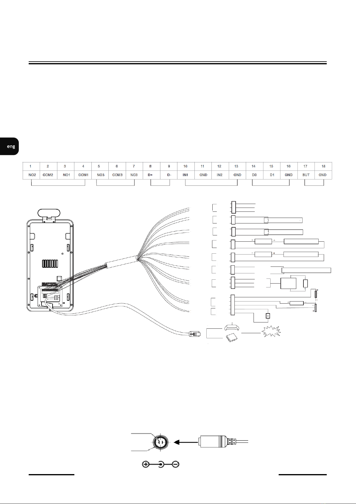
2.1. Description of connectors....................................................................................8
2.2. Terminal mounting requirements .......................................................................9
2.3. Selection of the terminal mounting location......................................................10
2.4. The main factors influencing the temperature measurement.............................10
2.5. Terminal mounting ...........................................................................................11
2.6. Recommendations for temperature measurement .............................................12
2.7. Starting the terminal ..........................................................................................13
2.8. Initial configuration via touch screen ................................................................14
2.9. Initial configuration via web browser................................................................16
2.10. Security recommendations for network architecture and configuration..........17
3. NETWORK CONNECTION USING WEB BROWSER ..........................................14
3.1. Recommended PC specification for web browser .............................................18
3.2. Connection with terminal via web browser........................................................18
4. WWW INTERFACE - WORKING WITH TERMINAL..........................................20
4.1. Displaying live video..........................................................................................20
4.2. Face configuration..............................................................................................21
4.2.1 Face Match Config...................................................................................21
4.2.2. Face Database Management....................................................................22
4.3. Access Control configuration.............................................................................24
4.3.1. Access Control system config.................................................................24
4.3.2. Tampering Alarm Setting........................................................................24
4.3.3. Door Lock ...............................................................................................25
4.3.4. Wiegand Config ......................................................................................25
4.4. Image configuration ...........................................................................................26
4.4.1. Video/Audio............................................................................................26
4.4.2. White Light Control................................................................................26
4.4.3. Face Exposure .........................................................................................26
4.5. Alarm configuration ...........................................................................................27
4.5.1. Temperature Measurement......................................................................27
4.5.2. Mask Detection .......................................................................................27
5. FACTORY SETTINGS RESTORING........................................................................28
5.1. Software factory settings restoring via web browser .........................................28
5.2. Software factory settings restoring via NMS IPTool .........................................28
5.3. Hardware factory settings restoring ...................................................................29
6. MICRO SD CARD INSTALLATION .........................................................................29

KDH-KZ6000FR-IP - Skrócona instrukcja obsługi wer. 1.0
KDH-KZ6000FR-IP - User’s manual (short form) ver 1.0
All rights reserved © AAT SYSTEMY BEZPIECZEŃSTWA Sp. z o.o.
5
1. FOREWORD INFORMATION
1.1. General characteristics
• Detection of people with elevated temperatures
• Non-contact body temperature measurement using infrared
• Content analysis based on Deep Learning
• Configuration of the door unlocking mode
• Human-sounding voice prompts
• Web-server
• Detection of people not wearing masks
• Measuring accuracy up to +/- 0,3°C
• Alarm Outputs
• Data storage on microSD card
• 8-inch LCD touch screen
• Two-way audio
• Wall mounting bracket included
• 12VDC Power Supply
FOREWORD INFORMATION

KDH-KZ6000FR-IP - Skrócona instrukcja obsługi wer. 1.0
KDH-KZ6000FR-IP - User’s manual (short form) ver 1.0
All rights reserved © AAT SYSTEMY BEZPIECZEŃSTWA Sp. z o.o.
6
FOREWORD INFORMATION
1.2. General characteristics
OPERATING SYSTEM
OS Embedded LINUX
Configuration Via touch screen, via web-browser
DISPLAY
Display Screen 8-inch LCD touch screen
Resolution 1280x800
Contrast 500:1
TEMPERATURE MEASUREMENT
Measurement range 32~43⁰C
Measurement accuracy ± 0.3 ⁰C
Measurement distance 0.25~0.75m
BUILT-IN CAMERA
Sensor 2 MPX, 1/2.8”
Lens Dual-lens, f=3.97mm/F1.6
WDR 120db
FACE RECOGNITION
Height range of face
recognition 1.2~2.2m (the recommended installation height is 1.35~1.5m)
Face recognition distance 0.3~2m
Face recognition duration ≤ 0.5 s per person
Face capacity 20 000
Face recognition accuracy 99.7%
SUPPLEMENTARY LIGHT
Built-in Soft white light, IR light
Light distance 1~3m
AUDIO
Two-way talk Yes (noise reduction and echo cancellation)
Audio Input Built-in microphone
Audio Output Built-in speaker
INTERFACE
Network Interface 1 x Ethernet - RJ-45 interface, 10/100 Mbit/s
Alarm Input 2
„Exit button” Input 1
Alarm Output 2
Door lock Output relay type, NO/NC (option), adjustable delay and duration
Wiegand Interface Input / Output (26/34)
RS-485 1 (half duplex)
SD card Interface 1 x microSD, up to 128GB
USB Interface 1
Ani-Tamper Interface 1
RESET button 1
OTHERS PARAMETERS
Power Supply 12 VDC
Power Management Screen Sleep, Screen Protection
Power Consumption 12W
Weight 1.2kg
Installation Wall mounting (bracket included)
Protection Surge Protection
Operating Temperature 0⁰C~40⁰C, <95% humidity (non-condensing)
Dimensions (mm) 302 x 138.5 x 34

KDH-KZ6000FR-IP - Skrócona instrukcja obsługi wer. 1.0
KDH-KZ6000FR-IP - User’s manual (short form) ver 1.0
All rights reserved © AAT SYSTEMY BEZPIECZEŃSTWA Sp. z o.o.
7
FOREWORD INFORMATION
1.3. Dimensions (mm) and physical components.
KDH-KZ6000FR-IP terminal
1.4. Package contents
After opening, make sure that the following elements are inside:
• KDH-KZ6000FR-IP device
• Accessories bag
• Short version of user’s manual
If any of this elements has been damaged during transport, pack all the elements back into the original
box and contact your supplier for further assistance.
CAUTION!
It is forbidden to connect devices called “passive PoE power supply”. Damages caused by the
usage of improper power supply source are not covered by the warranty.
White light
Temperature
Measurement
Module
Infrared
Light
Cameras
Display
Screen
Speaker
MicroSD
Card Slot
Reset button
USB Port
Microphone
Sabotage
button
Connector
terminal
Power
Interface
Network
Interface
138 34
301

KDH-KZ6000FR-IP - Skrócona instrukcja obsługi wer. 1.0
KDH-KZ6000FR-IP - User’s manual (short form) ver 1.0
All rights reserved © AAT SYSTEMY BEZPIECZEŃSTWA Sp. z o.o.
8
START-UP AND INITIAL TERMINAL CONFIGURATION
2. START-UP AND INITIAL TERMINAL CONFIGURATION
CAUTION!
If the device was brought from a location with lower temperature, please wait until it reaches
the temperature of location it is currently in. Turning the device on immediately after bringing it
from a location with lower ambient temperature is forbidden, as the condensing water vapour
may cause short-circuits and damage the device as a result.
Before starting the device familiarize yourself with the description and the role of particular
inputs, outputs and adjusting elements that the device is equipped with.
2.1. Description of connectors
When connecting access control devices such as a card reader or controller with the Wiegand
connector, you must first switched Wiegand mode to input or output mode.
The RS 485 interface of this device supports access to the access control security module. After the
security module is enabled, the exit button and the lock control will be inactive.
CAUTION!
In order to provide protection against voltage surges/lightning strikes, usage of appropriate
surge protectors is advised. Any damages resulting from surges are not eligible for service
repairs.
12VDC(+)
GND(-)
Schema of 12 VDC power supply connector
Alarm outputs Lock interface RS-485 Alarm inputs Wiegand interface Exit
Button
interface
12V
PE
GND
IN1
GND
IN2
GND
COM1
NO1
COM2
NO2
D+
D-
D0
D1
GND
NC3
COM3
NO3
Przycisk
GND
Router
Or
Switch
Internet
Exit Button
Power
Power
Power
+12V
Earth
GND
Alarm Input Device
Alarm Input Device
Alarm Output Device
Alarm Output Device
RS485+
RS485- Access Control Security Module
D0
D1
GND
Power
Card
Reader

KDH-KZ6000FR-IP - Skrócona instrukcja obsługi wer. 1.0
KDH-KZ6000FR-IP - User’s manual (short form) ver 1.0
All rights reserved © AAT SYSTEMY BEZPIECZEŃSTWA Sp. z o.o.
9
START-UP AND INITIAL TERMINAL CONFIGURATION
CAUTION!
Pay special attention that the alarm outputs are properly connected and that the maximum
load is not exceeded.
2.2. Terminal mounting requirements
In order to avoid problems with incorrect measurement, it is recommended to observe the following
mounting requirements. Before installing the terminal, it is recommended to carefully plan the
installation place. In case of problems, please contact your dealer or the technical support department.
• Keep the terminal away from moisture, dust and soot - suspended solids can settle near the
thermometer, blocking the temperature measurement or causing an incorrect reading.
• Do not block the terminal's ventilation - the device has been designed so that it releases heat
quickly enough.
• The terminal (and in particular its thermometer) cannot be exposed to wind or other gusts of air
- temperature changes have a negative effect on the temperature measurement.
• It is recommended to install the terminal in a no-wind indoor environment and keep the ambient
room temperature between 15 °C and 30 °C.
• In the event of a temperature drop, long shutdown, or first startup, it is recommended to leave
the terminal for about 30 minutes after turning on the power in order to achieve thermal
equilibrium.
• Do not place or install the terminal in a place exposed to sunlight or near a heat source. Avoid
direct sunlight, reflections, and backlighting. The thermometer in the terminal is sensitive to
light waves. The device should be at least 2 meters from light sources and at least 3 meters from
windows and doors.
• Make sure that the terminal can capture faces easily - that is, people are free to approach it, there
are adequate lighting and no light is reflected in the lens.
CAUTION!
Please note that the wall must have enough strength to carry the terminal with holder.
COM1
NO1
COM2
NO2
Power signaling device,
max. load 30VDC 1A
signaling device,
max. load 30VDC 1A
Power

KDH-KZ6000FR-IP - Skrócona instrukcja obsługi wer. 1.0
KDH-KZ6000FR-IP - User’s manual (short form) ver 1.0
All rights reserved © AAT SYSTEMY BEZPIECZEŃSTWA Sp. z o.o.
10
START-UP AND INITIAL TERMINAL CONFIGURATION
2.3. Selection of the terminal mounting location
In order to mount the terminal, select the installation location in accordance with the following
guidelines:
• Avoid direct sunlight, reflections, and background lighting.
• Keep the distance of the terminal from windows and doors of min. 3m.
• Keep the distance of the terminal from other light sources at least 2m.
• Avoid hot objects (e.g. light bulb, fluorescent lamp) in the field of view of the camera.
• Avoid incident light sources directly into the camera at a horizontal 30 ° angle.
• Avoid air conditioning, heating, air outlets, and glass surfaces.
2.4. The main factors influencing the temperature measurement:
• Wind - gusts of air both change the temperature of the terminal and the body of the person,
which affects the accuracy of the measurement.
• Sweating - the body's natural way to automatically cools down and dissipates heat, causing the
temperature to drop.
• Room temperature - too low temperature in the room causes the surface temperature of the
human body to drop. Too high a room temperature causes the human body to sweat, which
affects the accuracy of temperature monitoring.

KDH-KZ6000FR-IP - Skrócona instrukcja obsługi wer. 1.0
KDH-KZ6000FR-IP - User’s manual (short form) ver 1.0
All rights reserved © AAT SYSTEMY BEZPIECZEŃSTWA Sp. z o.o.
11
2.5. Terminal mounting
To install the terminal, please follow the steps below:
• Referring to the location of the holes in the terminal holder (1) and using the mounting
template, mark the points for future mounting holes and the cable entry.
• Drill mounting holes and a hole for the wires.
• Mount the terminal holder (2) using the supplied plugs and screws.
• If necessary, unscrew the service panel on the terminal, insert the memory card and screw the
terminal service panel.
• Connect the terminal wires and cover them with a wires cover (if possible), passing the wires
through the dedicated wires entry(3).
• Place the terminal on the holder and screw it(4).
START-UP AND INITIAL TERMINAL CONFIGURATION
Wires cover
Wires entry
Screws

KDH-KZ6000FR-IP - Skrócona instrukcja obsługi wer. 1.0
KDH-KZ6000FR-IP - User’s manual (short form) ver 1.0
All rights reserved © AAT SYSTEMY BEZPIECZEŃSTWA Sp. z o.o.
12
2.6. Recommendations for temperature measurement:
START-UP AND INITIAL TERMINAL CONFIGURATION
Odległość pomiaru Wysokość pomiaru Strefa pomiaru
Zasłonięte czoło Zasłonięte czoło
Measurement distance Measurement height Measurement zone
Covering the forehead Covering the forehead Wrong height
0.3m
0.4m
1.35~1.5m
Lens line
Recommended mounng height: 1.35 ~ 1.5m
Recommended measure range
The area of eecve temperature measurement
Area coverage in the height range of 1.4 ~ 2.2m
Short Tall
0.3m
0.4m
1.35~1.5m

KDH-KZ6000FR-IP - Skrócona instrukcja obsługi wer. 1.0
KDH-KZ6000FR-IP - User’s manual (short form) ver 1.0
All rights reserved © AAT SYSTEMY BEZPIECZEŃSTWA Sp. z o.o.
13
2.7. Starting the terminal
To run the terminal you have to power in from 12VDC power supply compatible with terminal power
supply specification. Additionally, connect the Ethernet cable to the RJ45 network interface of the
terminal and to a network switch.
After connecting power terminal display will turn on. Initialization process takes about 2 minutes.
The recommended way to start and configure terminal is a direct connection to the network switch
which is not connected to other devices. In the absence of a switch, it is enough to use a cable
connected directly to the computer. To obtain further information about network configuration
parameters (IP address, gateway, network mask, etc.) please contact your network administrator.
• Connection using network switch
• Connection directly to computer
Information:
Power supply adapter is not included. Please use power adapter with parameters specified in user ‘s
manual.
START-UP AND INITIAL TERMINAL CONFIGURATION
Terminal
Network transmission
Network transmis-
Switch Computer
Terminal
Network transmission
Computer

KDH-KZ6000FR-IP - Skrócona instrukcja obsługi wer. 1.0
KDH-KZ6000FR-IP - User’s manual (short form) ver 1.0
All rights reserved © AAT SYSTEMY BEZPIECZEŃSTWA Sp. z o.o.
14
2.8. Initial configuration via touch screen
Part terminal configuration can be done via built-in touch screen.
To enter the terminal menu, touch the Menu icon, and then in the login window, enter the login,
password and touch the OK button. The default login is admin and the password is 123456.
START-UP AND INITIAL TERMINAL CONFIGURATION

KDH-KZ6000FR-IP - Skrócona instrukcja obsługi wer. 1.0
KDH-KZ6000FR-IP - User’s manual (short form) ver 1.0
All rights reserved © AAT SYSTEMY BEZPIECZEŃSTWA Sp. z o.o.
15
For network parameters, touch the Network Settings icon and then select them with applicable
regulations.
Knowing the terminal’s IP address you need to appropriately set PC IP address, so the two devices can
operate in one network subnet ( e.g. for IP 192.168.1.250, appropriate address for the terminal ranges
from 192.168.1.2 to 192.168.1.249, for example 192.168.1.60). It is not allowed to set the same
addresses for terminal and PC computer
START-UP AND INITIAL TERMINAL CONFIGURATION

KDH-KZ6000FR-IP - Skrócona instrukcja obsługi wer. 1.0
KDH-KZ6000FR-IP - User’s manual (short form) ver 1.0
All rights reserved © AAT SYSTEMY BEZPIECZEŃSTWA Sp. z o.o.
16
2.9. Initial configuration via web browser
You can configure terminal’s network configuration via web browser. The default network settings for
KDH-KZ6000FR-IP terminal are :
1. IP address - 192.168.1.200
2. Network mask - 255.255.255.0
3. Gateway - 192.168.1.1
4. User name - admin
5. Password - 123456
Using Internet Explorer web browser you can set a network configuration (IP address, gateway, net
mask, etc.) of terminal yourself or select DHCP mode (DHCP server is required in this method in target
network) by using web browser or by NMS software. When you use DHCP server check IP address
lease and its linking with terminal MAC address to avoid changing or losing IP address during device
operation or network/DHCP server breakdown. You have to remember to use a new terminal IP
address after changing network parameters.
After network setting configuration has been done, the terminal can be connected to a target network.
START-UP AND INITIAL TERMINAL CONFIGURATION

KDH-KZ6000FR-IP - Skrócona instrukcja obsługi wer. 1.0
KDH-KZ6000FR-IP - User’s manual (short form) ver 1.0
All rights reserved © AAT SYSTEMY BEZPIECZEŃSTWA Sp. z o.o.
17
2.10. Security recommendations for network architecture and configuration
CAUTION!
Below are shown security recommendations for network architecture and configuration
of CCTV systems that are connected to the Internet to reduce the risk
of unauthorized interference with the system by a third party.
1. Absolutely change the default passwords and user names (if the device gives this possibility) of
all applied network devices (recorders, cameras, routers, network switches, etc.) to the
severely complexity password. Use lowercase and uppercase letters, numbers, and special characters
if there is such possibility.
2. Depending on the available functionality in the order to restrict access to the used network devices at
the administrator account level, it is recommended to configure the users accounts accordingly.
3. Do not use DMZ function (Demilitarized zone) in your router. Using that function you open the
access to recorder system from the Internet on all ports, which gives possibility for an unauthorized
interference with the system.
Instead of DMZ use port forwarding redirect only the ports which are necessary for the performance
of the connection.
4. Use routers with firewall function and make sure it is enabled and properly configured.
5. It is recommended to change the default network communication port numbers of used devices
if there is such possibility.
6. If used network devices has aUPnP feature and it is not used, turn it off.
7. If used network devices has aP2P feature and it is not used, turn it off.
8. If used network devices support HTTPS protocol for connection, it is recommended to use it.
9. If used network devices support IP filtering for authorized connections function, it is recommended
to use it.
10. If used recorder has two network interfaces it is recommended to use both of them to physically
separate network for terminals and network for Internet connection. The only device in the system,
accessible from Internet will be recorder - there will be no physically access directly to any terminal.
START-UP AND INITIAL TERMINAL CONFIGURATION

KDH-KZ6000FR-IP - Skrócona instrukcja obsługi wer. 1.0
KDH-KZ6000FR-IP - User’s manual (short form) ver 1.0
All rights reserved © AAT SYSTEMY BEZPIECZEŃSTWA Sp. z o.o.
18
3. NETWORK CONNECTION USING WEB BROWSER
3.1. Recommended PC specification for web browser
Requirements below apply to connection with an IP camera, assuming smooth image display in
1920x1080 resolution and 25 fps speed.
1. CPU Intel i5 3 GHz or faster
2. RAM Memory min. 4 GB
3. VGA card Nvidia GeForce 1GB
4. OS Windows 10
5. Network card 100/1000 Mb/s
3.2. Connection with terminal via web browser
CAUTION:
To maintain correct operation as snapshot or video recording you must run the browser as an
administrator.
You have to enter terminal address in the Internet Explorer web browser address bar. If IP address is
correct user login window will be displayed:
In the Language box you can change the display language. Available languages: Polish, English and
others.
CAUTION!
Default user is admin and default password is 123456. The terminal will ask you to change the default
password during the first login (recommended). To do this, check the Modify password option and then
enter and confirm the new password. In order to log into the camera without changing the password,
press the OK button. The message will be displayed each time you log in, until you change your
password, or select the Do not show again option.
NETWORK CONNECTION USING WEB BROWSER

KDH-KZ6000FR-IP - Skrócona instrukcja obsługi wer. 1.0
KDH-KZ6000FR-IP - User’s manual (short form) ver 1.0
All rights reserved © AAT SYSTEMY BEZPIECZEŃSTWA Sp. z o.o.
19
If you’re first time running the terminal, you will see the screen as below.
To correctly camera working, you need a NetAIIPCamera plugin. You have to download and install
it. To do it just click Save button, then Run, close IE browser, choose the language, click Install
button and at the end click Finish button. After installation run IE browser.
CAUTION!
In Windows Vista/7/8/8.1/10 the ActiveX applet may be blocked by Windows Defender or User
account control. In such case you should allow to run this applet, or simply disable these functions.
CAUTION!
If the installation fails, changing security settings for the IE browser is required. In order to do that,
please select Enable for Initialize and script ActiveX controls not marked as safe and Download
unsigned ActiveX controls option
NETWORK CONNECTION USING WEB BROWSER

KDH-KZ6000FR-IP - Skrócona instrukcja obsługi wer. 1.0
KDH-KZ6000FR-IP - User’s manual (short form) ver 1.0
All rights reserved © AAT SYSTEMY BEZPIECZEŃSTWA Sp. z o.o.
20
4. WWW INTERFACE - WORKING WITH TERMINAL
4.1. Displaying live video
1. Terminal tab:
• Live - opens the terminal live video
• Config - opens the terminal configuration menu
• Data record - opens the terminal menu with saved data about faces with temperature
• Search - opens the terminal playback
• Logout - button used to log out current user
2. The buttons for changing the displayed stream and fluency - allow to change the displayed stream to
Main stream, Sub stream, Third stream and also allow you to choose between Real-time, Balanced and
Fluent fluency.
3. Alarm icons - icons showing the current status of some terminal alarms.
4. Live video window
5. Image settings buttons - these buttons change the picture display mode in the live video preview
Original size Adapt
Proper size Full screen
6. Function buttons - these buttons allow you to enable / disable some of functions
Stop live view Snapshot Zoom In/Zoom Out (digital)
Start recording Start two-way audio
Start audio Start Face Detection preview function
WWW INTERFACE - WORKING WITH TERMINAL
3
4
6
5
2
1
Other manuals for KDH-KZ6000FR-IP
1
Table of contents
Languages:
Other AAT Touch Terminal manuals