Scorpio 1800 Installation Instructions
Plumbing Manifold
Tap & Waste Connecction
Connect the taps using the flexible water pipes provided making sure they do not snag when the bath
is lifted.Trimming of the inner lower & outer upper panels may be required to fit the panels around
the pipe.The waste is pre-assembled. Connect the flexible pipe to the waste outlet. Fit the manifold to
the floor and connect as detailed.
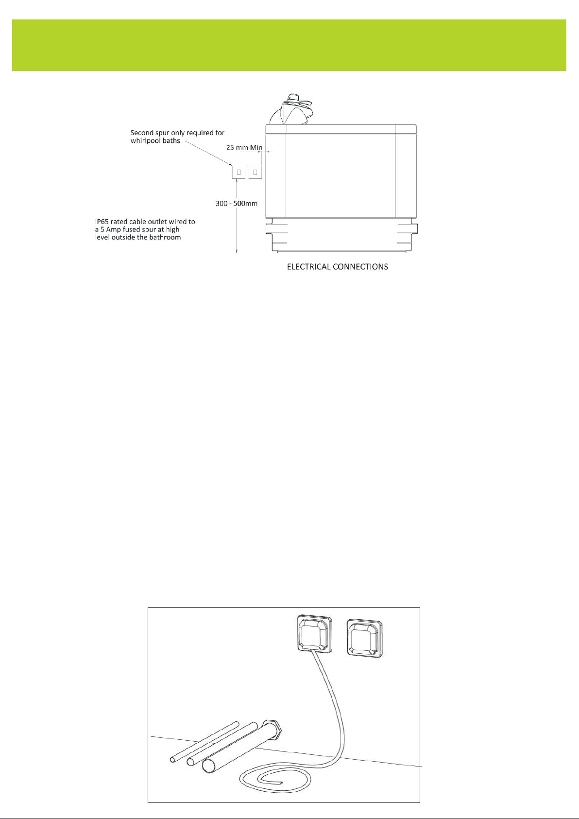
Electrical Connection
The control unit is located in the centre of the underside of
the bath. A prewired lead is supplied and this should be run to
the mains supply as per the pre-install connections.The
handset should be plugged in the control box as per FIG 3.
Ensure the lead retaining clip is refitted once the
handset has been connected.
Panel Fixing
The bath shell comes complete with the outer upper panels fitted.These should fit outside the inner
lower panels and should not touch them. Note: if the upper and lower panels touch, marking will occur.
Adjustment is possible on the bayonet clip if required.
Inner Panel Fitting
Offer the corner inner end panels (right and left) up to the bath and secure
using the M4 x 12mm white plastic topped machine screws
supplied (Fig.a) Screw through holes in panels and into
the rivnuts positioned in the frame uprights.
Use the white plastic binding fixings (Fig. b) to secue the inner panels together.
There will be one half of the screw assembly already bonded in each hole. Use
a quantity of 2 to connect the right corner inner panel to the left corner inner panel.
Use a quantity of 2 to connect the inner centre panel to the right and left corner
panels either side.
Sliding Panels
The Bath will be delivered with the sliding bracket metal-work
assembled (Fig. c)
This assembly will be fixed to the bath using 2
M8 Hex bolts through the slots and into the threaded
holes in the bath support bars.
It is important that the plate is square to the support
bars as it is crucial that the sliding brackets are
parallel to the sliding panel. If not the
panel will not rise and
fall as intended.
a.
b.
Sliding Panel Bracket
Qty x4 per bath Sliding Panel Plate
Qty x2 per bath
c.
10