Abatement Technologies AIRE GUARDIAN AG8000 User manual

AG8000_MN-FC 2023.12.06
AIRE GUARDIAN®AG8000
Hard-sided Mobile Containment Unit
INSTRUCTION MANUAL
Covered by one of more of the following:
U.S. Patent No. 9,574,399
U.S. Patent No. 10,195,979
Canada Patent No. 2,895,016
Abatement Technologies
Abatement Technologies, Inc.
Georgia, USA
+1 800 634 9091
Abatement Technologies Limited
Ontario, Canada
+1 905 871 4720
www.abatement.com

1
©Abatement Technologies 2014 All Rights Reserved. No reproduction of any portion of
this work is permitted without the express written permission ofAbatement Technologies,
Inc.
READ AND SAVE THESE INSTRUCTIONS!
Note: 1. Read and understand all operating instructions before using the AIRE
GUARDIAN® AG8000.
2. Save this manual for future reference.
This manual provides important information on the features and usage of the AIRE
GUARDIAN® AG8000 Hard-sided Mobile Containment Unit. These instructions must be
carefully followed in order to assemble and use the components safely and correctly. If
you have any questions regarding this system, please call Abatement Technologies® at
+1 800 634 9091 (US) or +1 905 871 4720 (Canada) for assistance or to request a digital
copy of this manual.
Table of Contents
Important Safety Instructions........................................................................................... 1
General Information......................................................................................................... 3
Transporting Between Facilities..............................................................................3
Feature Identification....................................................................................................... 4
Optional Accessories..............................................................................................7
Operating Instructions..................................................................................................... 8
Basic Operation ......................................................................................................8
Suggested Operating Procedure...........................................................................14
Care of the Unit............................................................................................................. 15
Aire Guardian® AG8000 Specifications ........................................................................ 15
Certification Of Mobile Containment Units ............................................................17
Limited Warranty...................................................................................................17
Extension Ladder Warning and Instruction Labels................................................18
AG8000 Wiring Diagram ............................................................................................... 19
IMPORTANT SAFETY INSTRUCTIONS
Warning: Failure to follow all instructions may result in serious personal injury or
death!
Warning: This mobile containment unit is made primarily of metal. Metal conducts
electricity. Use extreme caution when using near electrical circuits, equipment, or
other electrical conductors!

2
Warning: Do not use around exposed energized lines or equipment. Power to the
lines in the area of work must be turned off and protected from being turned on
with a lockout-tagout.
Warning: Do not use this unit near sparks, open flames, or other possible sources of
ignition.
Warning: Do not enter unit without all four casters being locked and stable!
Warning: Pinch hazard! Do not use hands or fingers to unlock swivel casters or
personal injuries such as severe pinching or cuts could result. Use work shoe to
lock and unlock casters.
Do not leave cart unattended without locking all four casters.
All four casters must be locked before entering the AIRE GUARDIAN® AG8000.
The AIRE GUARDIAN® AG8000 is for use by one person only. Maximum load capacity
is 900 pounds.
Use extreme caution when entering or exiting the AIRE GUARDIAN® AG8000.
Never move the unit while someone is inside! Always check to be certain no one is inside
the unit before moving it.
Use only on level, dry surfaces. Do not use on slippery surfaces.
Do not put anything under the base or wheels of the AIRE GUARDIAN® AG8000.
Do not use in front of doors that could unexpectedly be opened into the AIRE
GUARDIAN® AG8000.
Only use where allowed under federal, provincial, state, local, and facility regulations.
Inspect for damage before each use. Be sure all parts are present and in working order.
Abatement Technologies strongly urges all users of the AIRE GUARDIAN® AG8000 to
follow the most recent guidelines and/or standards published by the Occupational Safety
and Health Administration, Environmental Protection Agency, and all other federal, state,
provincial, local and employer regulations. In addition, the proper personal protective
equipment should be used at all times.
Before using, learn and understand your facility’s Infection Control Risk Assessment
(ICRA). Follow all Centers for Disease Control (CDC) and Association for Professionals
in Infection Control and Epidemiology (APIC) recommendations.

3
GENERAL INFORMATION
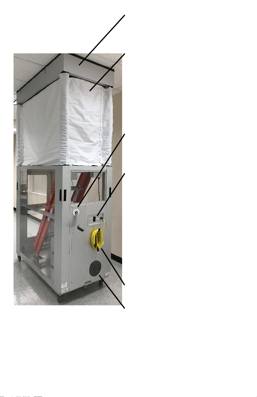
The AIRE GUARDIAN® AG8000 is a mobile containment unit designed to capture and
contain particulate during ceiling access work on ceiling heights up to 10'-2". Ceiling
heights up to 12'-2" can be reached with the Extension (P/N: AG8000-EXT24, sold
separately). Additionally, a Side Access Panel (P/N: AG8000-SA, sold separately) can be
installed to provide containment while doing wall access projects. Numerous user-friendly
featureshelp maintain superior levels of patient protection, worker safety, and productivity
unmatched by any other hard sided cart.
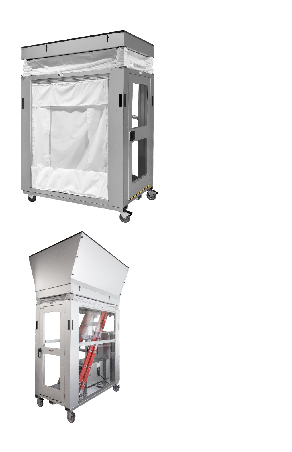
The AG8000 is designed to comply with ICRA requirements for projects requiring ceiling
access and limited wall access. The unit and its accessories can be used to meet various
mitigation activities which are required by the ASHE Infection Control Risk Assessment
2.0 Matrix of Precautions for Construction, Renovation and Operations and other
regulating documents. These activities include, but are not limited to
•Airborne dust dispersion prevention.
•Neutral to negative pressurization.
•Barriers that extend to the ceiling.
•Indoor air exhaust that is HEPA filtered.
•An impermeable temporary containment vessel.
The AIRE GUARDIAN® AG8000 is designed to be used with the provided extension
ladder only and should not be used with any other ladder. Read all instructions within this
manual as well as all danger, caution, and instruction labels affixed to the ladder.
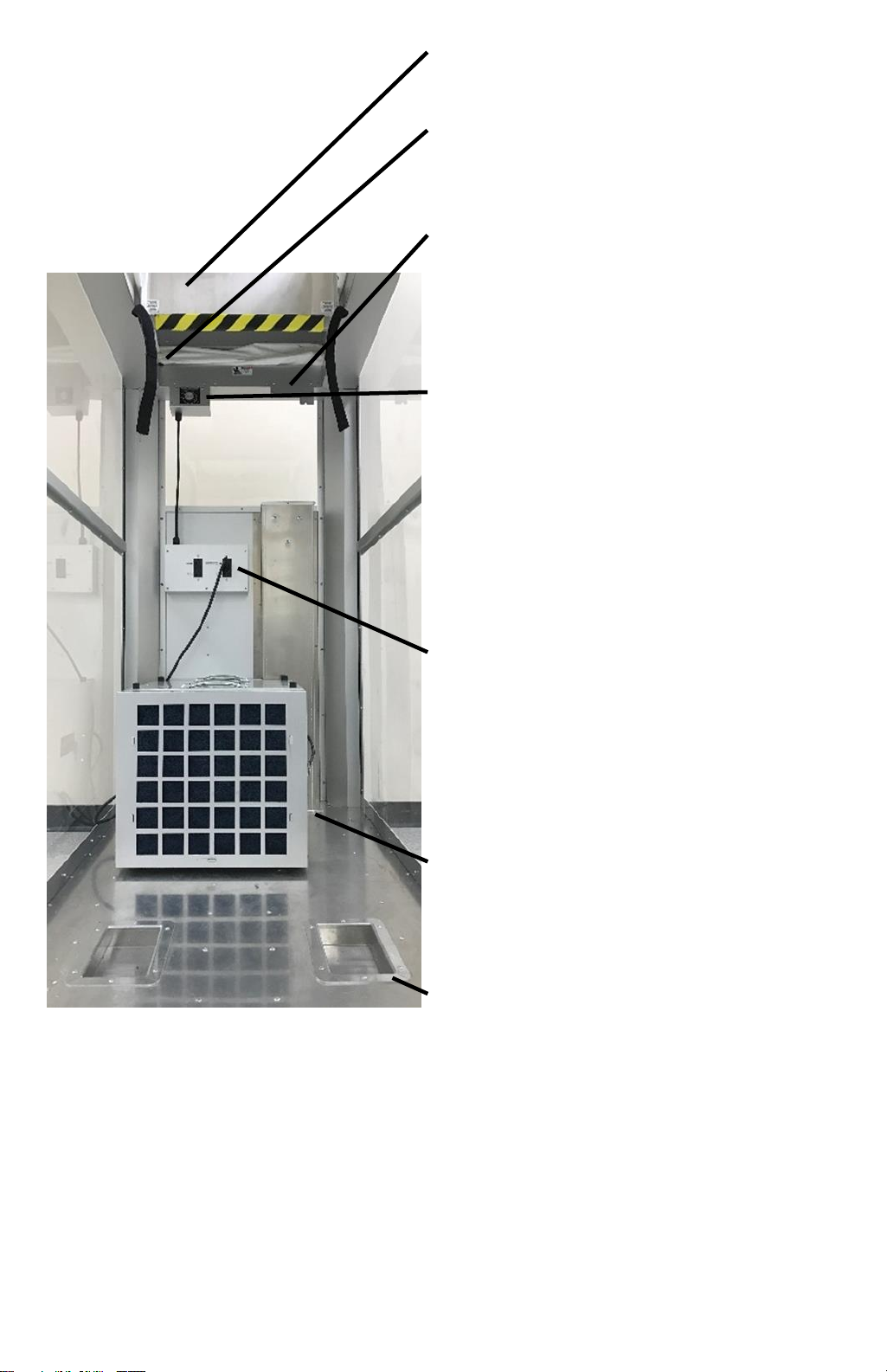
This unit should be used in conjunction with an air scrubber in order to meet ICRA
requirements where required. The AG8000 was designed to accept the PAS750 Portable
Air Scrubber (sold separately) inside the unit, but has the flexibility to have an external air
scrubber ducted to the unit's port (P/N: AG8000CADK, sold separately).
This manual provides instructions on how to use the features of the AIRE GUARDIAN®
AG8000, however, the procedure and/or order of operations in which it is used should be
determined by the healthcare facility's ICRA plan. Any procedural information
contained within this manual is to be taken as a suggestion only to help the user
understand some of the design intent of the unit.
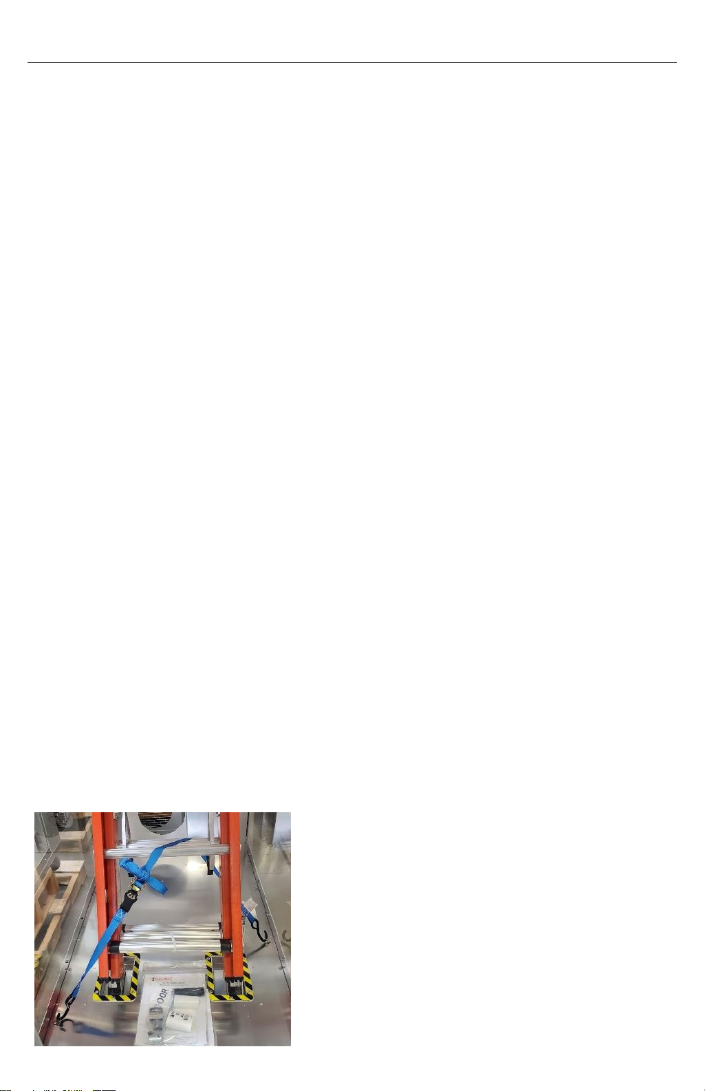
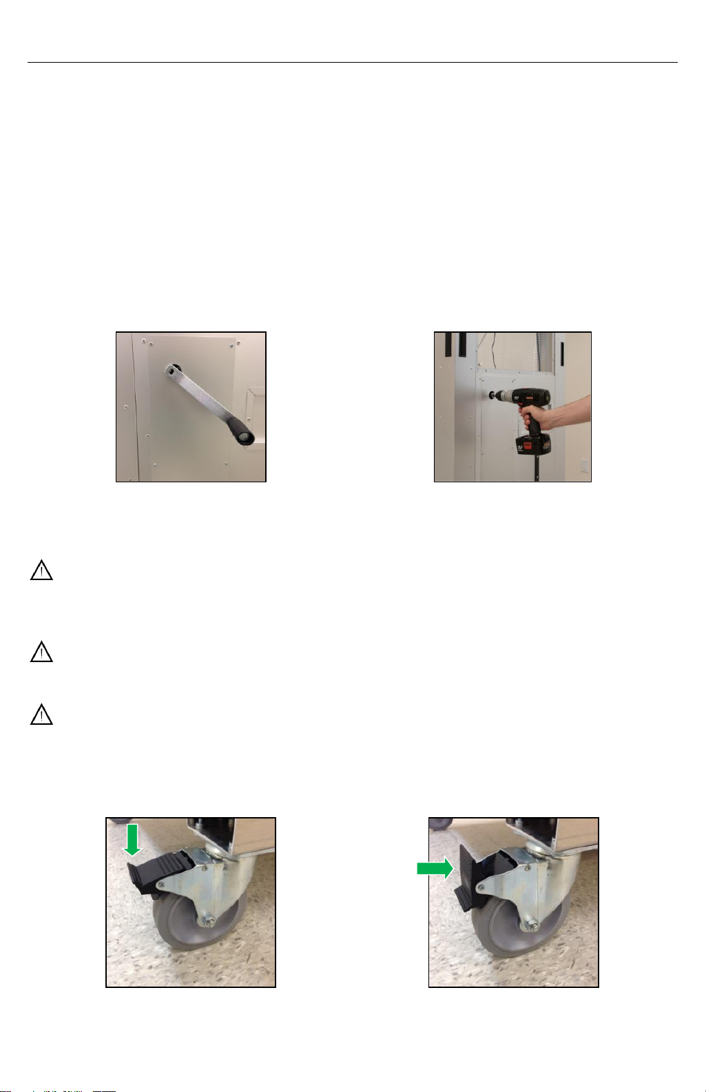
TRANSPORTING BETWEEN FACILITIES
The AG8000 should be secured to ensure that the
unit does not roll during transport and transported
in its normal position (resting on its casters). If
extremely poor road conditions exist, or excessive
shock and vibration are expected, take
precautionary measures by padding the unit to
provide impact absorption during transport.
Additionally, secure the ladder to the floor with the
included ratchet strap (P/N: HARDWRE209).

4
FEATURE IDENTIFICATION
A. Foam gasket. The 1" thick foam
gasket provides a seal against the
ceiling when the header is raised to
the ceiling.
B. Header opening markers. In order to
help align the unit, there are arrow
marks on the outside of the header
that indicate where the opening inside
the unit begins and ends. Position the
arrow furthest away from the door to
align with the ceiling grid.
C. 12" x 12" window & pass-thru. A total
of two clear windows allow visibility
into and out of the fabric enclosure.
The windows are attached via hook
and loop on three sides, enabling it to
be opened and act as pass-throughs
for items such as pipe or conduit.
D. Handles. A total of 8 handles are
located at the corners of the mobile
containment cart to assist in transport.
E. Fiberglass extension ladder. The
AIRE GUARDIAN® AG8000 was
designed around the included
fiberglass extension ladder and should
only be used with this ladder. Read all
warning and instruction labels
located on the ladder as well as the
instructions within this manual to
properly operate the ladder.
F. Door. Door opening of 54.5" H x 22"
W.
G. Casters. This unit has 4 lockable
swivel casters.
Lockable recessed handle. The lockable door helps
protect tools and equipment within the mobile
containment cart when not in use.
Note: To reduce the risk being locked out of the mobile
cart, Abatement Technologies suggests making a copy of
the key and storing the master in a secure place.

5
H. Header. The manual refers to this part
as the header, which is raised and
lowered using the provided hand crank
or a power drill with clutch (not
provided).
I. Fabric enclosure. The fabric enclosure
provides a flexible barrier that can
accommodate the raising and lowering
of the header. This enclosure is
constrained by the telescoping
members, which keeps it from
encroaching into the work space under
negative pressure. It is removable and
washable (replacement P/N:
AG8000ENC-FR)
J. Raising/lower mechanism. The
raising/lowering mechanism adjusts the
height of the header. This can be
operated by the provided hand crank or
a power drill with clutch (not included).
K. External receptacles. The unit comes
with a 3-prong male receptacle for
connection to a 120V 60Hz power
source that is used to power the female
receptacles on the unit. There is also a
receptacle that is designed specifically
for use with a PAS750 Portable Air
Scrubber unit (this receptacle is
connected to the remote variable speed
control inside the cart, DO NOT use with
any other device). The other receptacle
is a standard receptacle. A maximum of
15 amps can be used with AG8000’s
electrical system.
L. Cord wrap. Store an extension cord
around the cord wrap for convenience
(extension cord not included).
M. Intake/exhaust port. Acts as an exhaust
port when a PAS750 Portable Air
Scrubber unit is located inside the cart.
The AG8000CADK Caddy and
Connection Kit (not included) can be
attached on the outside for locating a
PAS750 or PRED750 externally.

6
N. Ladder bracket. The ladder bracket is
attached to the header and accepts the
top of the provided extension ladder.
O. Ladder straps. A ladder strap is located
on each side of the ladder bracket to
further secure the provided extension
ladder.
P. Pressure monitor mounting bracket. An
Abatement Technologies’ RPM series
pressure monitor can be installed inside
the unit on this mounting bracket. This
mounting bracket is included with all
units (pressure monitor sold separately).
Q. Remote variable speed control. There
are designated electrical sockets on the
inside and the outside of the unit that are
wired to the remote variable speed
control. Plugging a PAS750 Portable Air
Scrubber into these sockets allows
those units to be controlled with the
remote variable speed knob that can be
accessed while standing on the
extension ladder.
R. Internal GFCI receptacles. One
receptacle is designated for a PAS750
Portable Air Scrubber to allow remote
variable speed control (Q). The
remaining receptacles can be used for
other devices that run off of 110-
120VAC. A maximum of 15 amps can be
used with AG8000’s electrical system.
S. PAS750 Portable Air Scrubber (not
included). The optional PAS750 Portable
Air Scrubber unit is recommended in
order to create negative pressure for
particulate containment.
T. Recessed ladder pockets. There are two
recessed pockets in the floor that secure
the extension ladder’s feet to keep the
ladder from sliding and also to ensure
that the proper angle is kept.
U. Top cover (not shown). The top cover
closes the opening in the header to
provide full containment during transport
and during usage before ceiling tiles are
removed (replacement P/N:
AG8000TOP-FR).

7
OPTIONAL ACCESSORIES
An optional Side Access Panel
can be purchased for wall access
projects (P/N: AG8000-SA). Once
installed, the Side Access Panel
and the original clear
polycarbonate panel are
interchangeable.
An optional Extension can be
purchased to reach ceiling heights
of 12'-2"(P/N: AG8000-EXT24).
Additionally, it provides an
increased area of ceiling access.

8
OPERATING INSTRUCTIONS
BASIC OPERATION
Raising and lowering the header
The AG8000 uses a mechanical system to raise and lower the entire header at a single
operating point which is located on the back ofthe unit. Since this is a mechanical system,
electricity is not required for this operation. There are two ways to operate this
mechanism: (1) with the hand crank attachment (P/N: HARDWRE161) that is provided
with the unit or (2) with a power drill with clutch (not included). For the power drill option,
a bit for the drill is provided with the unit (3/8" socket adapter with a 5/8" socket). It is
highly recommended that the power drill has a clutch setting to help prevent over
extending the header into the ceiling (use the lowest clutch setting that is able to raise
the header to the ceiling).
Turn hand crank clockwise to raise the
header. Turn hand crank counter-
clockwise to lower the header.
Alternatively, a power drill can be used
to quickly and easily raise andlower the
header.
Warning: Do not overextend the header into the ceiling! This may cause damage to
the ceiling and/or the unit. Stop raising the header when the foam seal on the
header touches the ceiling.
Warning: Do not allow the header to collide with any devices or fixtures installed in
the ceiling or walls.
Warning: Be sure the ladder is retracted from the ladder bracket before lowering the
header!
Locking the casters
To lock the casters, push down on the
pedal with work shoe.
To unlock the casters, push the pedal
towards the wheel with work shoe.

9
Warning: Pinch hazard! Do not use hands or fingers to unlock swivel casters or
personal injuries such as severe pinching or cuts could result. Use work shoe to
lock and unlock casters.
Supplying Power to the Unit
Power needs to be supplied to the unit in order for any of the electrical outlets to be
functional, including the powering of the PAS750, if applicable. Note that the raising and
lowering of the header does not require electricity as it is operated by a mechanical
mechanism.
Power must be supplied to the AG8000
in order for any of the outlets to be
operational. Plug the female end of an
extension cord into the POWER
SUPPLY outlet located on the back
side of the unit and the male end into a
110V-120V, 60Hz, single phase outlet.
The AG8000 comes equipped with a
power cord wrap that is located below
the POWER SUPPLY outlet
(extension cord not included with
unit, P/N: AG8000CORD).
Using the fiberglass extension ladder within the AG8000
Important: Be sure to read and understand all warning and instruction labels located
on the ladder before using the ladder.
Place the feet of the ladderinto the recessed
pockets in the floor. Unbuckle the strap on
the left side of the ladder that secures the
three sections of the ladder together.
After raising the header to the
ceiling, the ladder can be extended
and placed against the ladder
bracket. Use the hook and loop
straps on each side of the ladder
bracket to secure the ladder.

10
After the fabric top is unzipped and the ceiling tile is
removed, the ladder can be extended above the ceiling,
if necessary.
Important: The ladder must be placed within the recesses in the floor to secure the
feet of the ladder and to maintain the minimum 75⁰ angle required per OSHA
requirements.
Opening and closing the top cover
The top cover has a zipper down each
long side and is secured by hook and
loop on the short side near the ladder.
Unzip the zippers on each side and
detach the hook and loop on the short
side near the ladder to open the top
cover.
Roll up the top cover and place it in the cove in
the header that is located opposite of the
ladder.

11
Using the pass-through
Two 12" x 12" windows located in the fabric
enclosure also act as a pass-through for
conduit or other materials that need to be fed in
fromthe outside ofthe mobile containment unit.
Each is secured by hook andloop along the top
and side edges and opens from the inside.
Using the remote variable speed control
If the PAS750 unit is located inside
the AG8000, plug the unit into the
outlet labeled “FOR 120VAC
VARIABLE SPEED DEVICE ONLY”
as shown in the picture above.
If the PAS750 or PRED750 unit is
located external to the AG8000, ensure it
is plugged into the outlet labeled “FOR
120VAC VARIABLE SPEED DEVICE
ONLY” as shown in the picture above.
Set the PAS750 to the highest setting
on the unit's variable speed control
knob.
The PAS750 is now ready to be
controlled with the remote variable speed
control.
Warning: Only use Abatement Technologies Portable Air Scrubber units with the
variable speed control. Other units may not be compatible with the variable speed
control and can result in fire, electrical shock, or personal injuries.

12
Transporting and positioning the AG8000 underneath ceiling tiles
Transport the AG8000 in the fully collapsed
position and use the handles located at the
corners of the unit to move the mobile containment
unit.
Position the mobile containment unit in
the approximate location where ceiling
access is required.
Raise the header within a fewinches of the
ceiling, ensuring that the unit can still be
moved without crashing into any objects.
-
After raising the header close to the ceiling, fine tune the positioning by aligning the
arrow marker closest to the back of the unit with the ceiling grid. After adjusting the
position as needed, raise the header until it seals against the ceiling. Be sure to lock
the casters before entering the unit.
Warning: Watch out for devices and fixtures installed in the ceiling and on the wall
while transporting the AG8000. Colliding with any devices or fixtures can cause
damage to the object it hits as well as damage the mobile containment unit.

13
Removing the fabric enclosure and top cover
Both the top cover and thefabric enclosure arefastened
to the mobile containment unit via hook and loop. To
remove the top cover, simply separate the hook and
loop along the perimeter of the top cover. To remove
the fabric enclosure, detach the hook fromthe loop from
each of the four telescoping members as shown above.
Then separate the hook and loop along the top
perimeter and then the bottom perimeter.
Installing an RPM series pressure monitor
Locate the pressure monitor mounting
bracket on the inside back wall of the
AG8000.
Remove the faceplate from the RPM series
pressure monitor by unscrewing the two small
screws on the sides of the pressure monitor.
Connect the reducing elbow to the “COM”
port of the monitor and attach tubing to the
other side of the elbow. Plug the power
connector into the terminal as shown. Hang
the monitor on the lower set of screws on the
mounting bracket.
Plug the tubing into the barb located in the
polycarbonate panel of the back wall.
Reattached the faceplate to the monitor by
tightening the two screws on the sides. Plug
the power adapter into one of the standard
120V receptacles inside the AG8000.

14
SUGGESTED OPERATING PROCEDURE
The following procedure is a general guideline that provides an order of operations
intended to contain particulate within the AG8000 mobile containment unit. Review your
healthcare facility's ICRA plan and use this cart accordingly.
1. Ensure the unit is decontaminated before each use and test the air scrubber to
ensure that it is working properly and that the filters do not need to be changed.
Note: There are two places that control the speed of the air scrubber unit: a knob
directly on the portable air scrubber unit, and a remote knob located on the wall
opposite of the door. The setting on the scrubber unit should be kept on the highest
setting and the speed adjustments should be made on the remote variable speed
control knob.
Warning: If using an air scrubber that is not manufactured by Abatement
Technologies, do not use the remote variable speed control in conjunction with the
air scrubber. Abatement Technologies air scrubbers have been tested to work with
the variable speed control; other units may not be compatible.
2. Seal the unit completely before moving the unit throughout the healthcare facility.
a. Make sure the top cover is in place, zipped up,and that the hook is engaged
to the loop in all places.
b. Make sure the soft sleeve is installed properly and that the pass-through
windows are closed.
c. Make sure the door to the unit is closed.
3. Position the unit in the approximate location under the ceiling tiles that will be
accessed.
4. Raise the unit using the raising mechanism with either the provided hand crank or
a power drill within a few inches of the ceiling.
Warning: Be sure that the upper header will not crash into any device installed in
the ceiling, such as sprinkler heads, sensors, etc. If using a power drill, be sure
that the header is not over extended as this can damage the ceiling grid and/or the
unit.
5. Using the arrow markers on the sides of the header, fine tune the position of the
cart by aligning the markers with the ceiling grid.
6. Carefully raise the unit until the ceiling gasket seals against the ceiling. Again, be
sure not to over extend the header such that the ceiling grid is damaged.
7. Lock all four of the casters by pressing the pedals on the casters down with your
work shoe.
8. Supply power to the unit by plugging a power cord into the power supply outlet in
the cart and into an outlet in the facility. Open the door and enter the unit. Be sure
to close the door before beginning any work inside.
9. Place the feet of the extension ladder into the recessed pocketsin the floor. Extend
the ladder and rest it against the ladder bracket that is attached to the header.
10.Climb up the ladder and strap the ladder into place using the hook and loop straps
located on the ladder bracket. Then, open the top cover by undoing the hook and
loop on the short edge of the cover near the top of the ladder. Then, unzip the two
zippers along the two long sides. Roll up the top cover and insert it into the top
cover pocket.
11.Remove the ceiling tile. The extension ladder may now be raised into the ceiling if
necessary to permit higher access into the ceiling.
12.Adjust the speed on the portable air scrubber as necessary using the remote
variable speed adjustment knob and then perform the required work in the ceiling
space.

15
13.When finished with the ceiling work, replace the ceiling tile and close the top cover
by zipping up the two zippers and engaging the hook and loop on the short edge
near the ladder.
14.Undo the hook and loop straps that secured the top of the ladder and then fully
collapse the ladder.
15.Before exiting the unit, be sure to decontaminate yourself and the inside of the
mobile containment cart using a HEPA filter vacuum.
16.Completely lower top header of the unit with the raising/lowering mechanism with
either the provided hand crank or a power drill.
17.Unplug the power supply cord and wrap the cord around the cord wrap, if
necessary.
18.Unlock all four of the casters by lifting the pedal on the casters up with your work
shoe.
19.Move the unit to the next desired location, being careful to avoid any contact with
signs or devices mounted on the walls or ceiling.
20.Repeat procedure starting from step 5, as needed.
CARE OF THE UNIT
Clean with a mild water based cleaner or soap and water. Do not use hydrocarbon
based cleaners.
Do not place items on the vinyl enclosure.
Do not subject the vinyl enclosure to sharp or abrasive objects.
Be sure all metal components are properly secured during transport and in storage
so they cannot fall and cause personal injury or property damage.
Do not expose the vinyl enclosure to high heat.
AIRE GUARDIAN® AG8000 SPECIFICATIONS
FEATURE
SPECIFICATION
Weight with ladder
325 lbs (147.4 kg) (air scrubber and pressure
monitor not included)
Maximum working ceiling
height
10'-2" [312 cm]
Unit Height, Fully Collapsed
6'-5.5" [196 cm]
Unit Length x Width
62" L x 32" W [157.5 cm L x 81.3 cm W]
Header opening dimensions
36" L x 22" W [91.4 cm L x 55.9 cm W]
Door
54.5" H x 22" W [138.5 cm H x 56 cm W] door
opening; lockable handle
Hardside wall material
Clear polycarbonate provides visibility and allows
light into the unit.
Hardside wall material UL94
flammability rating
V0
Fabric enclosure
Fabric enclosure is removable and secured by hook
and loop; includes two 12"x12" clear windows that
each acts as a pass-through (window secured by
hook and loop) (P/N: AG8000ENC-FR).

16
Top fabric
Top fabric is included with unit and secured by hook
and loop (P/N: AG8000TOP-FR).
Fabric fire retardant standard
ASTM-E84/NFPA701
Ladder
16' three-section fiberglass extension ladder with
300 lbs weight capacity (P/N: LADDER03).
Ladder weight
40.5 lbs (18.4 kg)
Exterior finish
Anodized aluminum
Header raising/lowering
Mechanical system raises/lowers entire header with
the provided hand crank or a power drill (not
included with unit); 5/8" socket connection.
Casters
4 ea swivel, lockable, non-marking rubber casters.
Pressure monitor mount
Bracket and tubing port built into unit (RPM series
pressure monitor sold separately).
Receptacles
External receptacles located on back of unit:
1 ea. three prong male receptacle to connect
power (power cord not included)
1 ea. receptacle for general use
1 ea. receptacle controlled by remote variable
speed knob located inside the unit
Internal receptacles:
3 ea. receptacles for general use
1 ea. receptacle controlled by remove variable
speed knob
All receptacles rated 15 A; entire circuit rated 15 A.
Scrubber speed control
Remote variable speed control knob located inside
unit allows for easy access control of an air scrubber
(scrubber sold separately).
Scrubber compatibility
Unit is designed to accept the PAS750 air scrubber
inside the unit; a PAS750 or PRED750 scrubber can
be located external to the AG8000.
Foam Gasket on Header
1" wide x 1" tall gasket around header perimeter to
seal against ceiling.
Exhaust port
10" diameter exhaust grille located on back of unit.
Caddy cart
Optional caddy cart assembly that attaches to
AG8000 is available for locating the scrubber
external to the unit (P/N: AG8000CADK).
Side Access
Optional Side Access Panel (P/N: AG8000-SA)
Storage Cover
Optional storage cover (P/N: AG8000SC)
Extension
Optional extension for ceilings up to 12'-2" and for
increased header nominal opening to 60" L x 46" W
(P/N: AG8000-EXT24)
Patents
Covered by one of more of the following:
U.S. Patent No. 9,574,399
U.S. Patent No. 10,195,979
Canada Patent No. 2,895,016

17
CERTIFICATION OF MOBILE CONTAINMENT UNITS
Abatement Technologies AG8000 mobile containment control panels
are independently tested and certified to the relevant safety
requirements by TÜV SÜD.
TÜV SÜD is accredited by the U.S. Occupational Safety and Health
Administration (OSHA) as a Nationally Recognized Testing Laboratory
(NRTL).
LIMITED WARRANTY
Abatement Technologies (AT) warrants that goods sold to the original user shall be free
from defects in material and workmanship for a period of 1 year, except such as are
commercially acceptable. AT does not warrant that the goods sold are merchantable
or fit for any particular purpose. AT makes no warranties other than as stated in
this paragraph. All other warranties, guaranties, or representations, express or
implied, by operation of law or otherwise, are expressly disclaimed. Goods found by
AT to be defective or not to conform to specification shall upon return be replaced or
repaired by AT without any additional charges, or, at AT’s option, AT may refund the
purchase price of such goods. AT will pay return transportation charges on returned
goods not exceeding the transportation charges applicable to shipment from original
destination unless the returned goods are free from defect and conform to specifications.
Returned goods which are found by AT to be free from defect and to conform to
specifications shall be held for Purchaser’s shipping instructions, which instructions
Purchaser shall furnish promptly upon request. AT’s liability shall in no event extend
beyond replacement, repair or refund of the purchase price and AT shall not be
liable under any circumstances for special, contingent or consequential damages,
nor for loss, damages, or expenses directly or indirectly arising from the use of the
goods, including without limitation, warehousing, labor, handling and service
charges, die, equipment, or machine breakage, nor for costs, lost profits or loss of
good will. The use of substitute, non-AT parts, in any AT product, voids all
warranties and performance claims. The remedies set forth herein are exclusive.
For warranty information and assistance contact Abatement Technologies’ Customer
Service Department at +1 800 634 9091 (U.S.) or +1 905 871 4720 (Canada).

18
EXTENSION LADDER WARNING AND INSTRUCTION LABELS

19
AG8000 WIRING DIAGRAM
Starting Serial Number: C800019402727
Table of contents