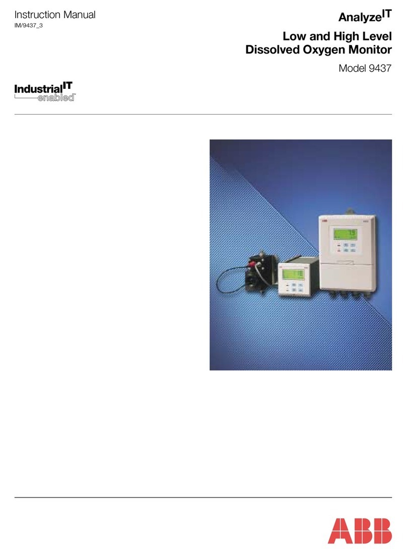
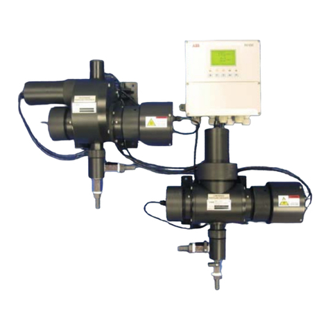
ABB 8242 User manual

Model 8242
Colorimetric Phosphate Monitor
Instruction Manual
All Versions
OUT OF SERVICE
ALARM 1
CAL
ALARM 2
HOLD
OUT OF SAMPLE
Phosphate 8242

0255
ABB AUTOMATION
The Company
ABB Automation is an established world force in the design and manufacture of
instrumentation for industrial process control, flow measurement, gas and liquid analysis and
environmental applications.
As a part of ABB, a world leader in process automation technology, we offer customers
application expertise, service and support worldwide.
We are committed to teamwork, high quality manufacturing, advanced technology and
unrivalled service and support.
The quality, accuracy and performance of the Company’s products result from over 100 years
experience, combined with a continuous program of innovative design and development to
incorporate the latest technology.
The NAMAS Calibration Laboratory No. 0255 is just one of the ten flow calibration plants
operated by the Company, and is indicative of ABB Automation’s dedication to quality
and accuracy.
Use of Instructions
Warning.
An instruction that draws attention to the risk of injury or
death.
Caution.
An instruction that draws attention to the risk of damage to
the product, process or surroundings.
Note.
Clarification of an instruction or additional information.
Information.
Further reference for more detailed information or
technical details.
Although Warning hazards are related to personal injury, and Caution hazards are associated with equipment or property damage,
it must be understood that operation of damaged equipment could, under certain operational conditions, result in degraded
process system performance leading to personal injury or death. Therefore, comply fully with all Warning and Caution notices.
Information in this manual is intended only to assist our customers in the efficient operation of our equipment. Use of this manual
for any other purpose is specifically prohibited and its contents are not to be reproduced in full or part without prior approval of
Marketing Communications Department, ABB Automation.
Health and Safety
To ensure that our products are safe and without risk to health, the following points must be noted:
1. The relevant sections of these instructions must be read carefully before proceeding.
2. Warning labels on containers and packages must be observed.
3. Installation, operation, maintenance and servicing must only be carried out by suitably trained personnel and in accordance with the
information given.
4. Normal safety precautions must be taken to avoid the possibility of an accident occurring when operating in conditions of high pressure
and/or temperature.
5. Chemicals must be stored away from heat, protected from temperature extremes and powders kept dry. Normal safe handling procedures
must be used.
6. When disposing of chemicals ensure that no two chemicals are mixed.
Safety advice concerning the use of the equipment described in this manual or any relevant hazard data sheets (where applicable) may be
obtained from the Company address on the back cover, together with servicing and spares information.
BS EN ISO 9001
St Neots, U.K. – Cert. No. Q5907
Stonehouse, U.K. – Cert. No. FM 21106
EN 29001 (ISO 9001)
Lenno, Italy – Cert. No. 9/90A
Stonehouse, U.K.
R
E
G
I
S
T
E
R
E
D

1
Section Page
1 INTRODUCTION ................................................. 2
1.1 Brief Description ................................................3
1.2 Training..............................................................3
1.3 Location and Function of
the Main Components .......................................3
2 INSTALLATION ................................................... 4
2.1 Accessories .......................................................4
2.2 Location .............................................................4
2.3 Mounting ............................................................4
2.4 Sampling Requirements ....................................4
2.5 Sample Connections .........................................5
2.6 External Electrical Connections .........................6
2.7 Relay Contact Protection and
Interference Suppression ..................................8
3SETTING UP .......................................................8
4LIQUID HANDLING SECTION............................ 9
4.1 Principle of Operation ........................................9
4.2 General Operation ........................................... 11
4.3 Multi-Stream Operation ...................................12
4.4 Manual Grab Sample Facility ..........................13
4.5 Optical System.................................................13
5ELECTRONICS SECTION ................................ 14
5.1 Front Panel Controls........................................14
5.2 Display .............................................................14
5.3 L.E.D. Indicators ..............................................14
5.4 Microprocessor Unit.........................................16
6SINGLE STREAM PROGRAMMING ................ 18
7CALIBRATION .................................................. 24
7.1 Method of Calibration ......................................24
7.2 Operation of Color Compensation ...................24
7.3 Calibration/Color Compensation Conflicts .......24
Section Page
8MAINTENANCE ................................................ 25
8.1 Chemical Solutions ..........................................25
8.1.1 Reagent Solution ...............................25
8.1.2 Standard Solutions.............................25
8.1.3 Rinse Solution for
Internal Pipework ...............................25
8.2 Scheduled Servicing ........................................26
8.2.1 Regular Visual Checks.......................26
8.2.2 Five-weekly ........................................26
8.2.3 Twelve-monthly ..................................26
8.2.4 Rinsing Internal Pipework ..................27
8.2.5 Consumable Spares Kit –
see Section 10 ...................................27
8.2.6 Peristaltic Pump .................................27
8.2.7 Replacement of Plumbing Tubing ......27
8.3 Shutdown Procedure .......................................27
8.4 Unscheduled Servicing ....................................30
8.4.1 Monitor Diagnostic Information ..........30
8.4.2 Malfunction of the Monitor..................30
8.4.3 Effects of Loss of Power
to the Monitor .....................................31
8.5 Simple Checks.................................................31
8.5.1 Unstable or Erratic Readings .............31
8.5.2 Low/High Calibration Factor Value.....32
8.5.3 Monitor Stability/Response Test.........32
8.5.4 Simple Electronic Response Test.......32
8.6 Setting Up the Optical System.........................32
8.6.1 Replacing the Exciter Lamp ...............32
8.6.2 Aligning the Exciter Lamp ..................33
8.6.3 Setting Up the Cuvette Board ............33
8.7 Color Compensation Solenoid Valves .............34
9SPECIFICATION ............................................... 34
10 SPARES ............................................................ 35
APPENDIX A – MULTI-STREAM
PROGRAMMING ....................................................... 37
APPENDIX B – WIRING SCHEMATIC...................... 44
APPENDIX C – REPLACING
SOFTWARE EPROM................................................. 44
CONTENTS

2
1INTRODUCTION
1.1 Brief Description
The Model 8242 Phosphate Monitor is a microprocessor-
based colorimetric analyzer that monitors the level of
phosphate in river and potable water supplies and also in
sewage/waste water treatment. The instrument is available as
a single stream or as a multi-stream version, the latter being
able to sequentially sample up to six independent streams.
The single stream version also incorporates a facility to
compensate for color in samples.
This manual covers both versions of the monitor; aspects
specific to the multi-stream version are covered in the text as
appropriate, but multi-stream programming is covered in
Appendix A.
1.2 Training
Due to the specialized nature of the above instrumentation, it
is recommended that, where personnel have had no previous
experience of maintaining this type of equipment, training be
provided by the Company. Such training is available via a
network of local or overseas agents, or may be carried out on
the users' premises.
1.3 Location and Function of the Main
Components – Fig. 1.1
The monitoring of phosphate involves the addition of a
chemical reagent solution to the sample under constant
temperature conditions. The result is a chemical complex, in
solution, which has a predetermined color. The absorbance of
this colored complex is proportional to the concentration of the
phosphate in the original sample, thus making it possible for
the measurement to be made optically.
Because some samples are naturally colored, the monitor has
a feature to compensate for interference from colored
samples. This feature is available in single stream monitors
only.
The 8242 Phosphate Monitor carries out the measurement as
follows:
a) The sample is presented to a constant head unit and any
excess is allowed to overflow. On multi-stream versions
there is a constant head unit for each stream.
b) A solenoid valve is then used to select automatically one
stream to be sampled sequentially. This allows sample,
under controlled pressure conditions, to be
c) presented to a multi-channel peristaltic pump which
d) proportions sample and reagent through a series of mixing
and reaction stages. The reaction stage is temperature
controlled to remove the effects of sample and ambient
temperature variations.
e) The reacted solution is then delivered to a small chamber,
called a cuvette, in the optical system where the
measurement takes place.
f) The output from the optical system, which is based on the
amountoflightabsorbed by the solution, isthenprocessed
by the microprocessor-based electronics section to
calculate the phosphate concentration in the sample.
Information. A facility is provided to pass a 'grab'
sample through the monitor manually which has been
taken from another sample point. This facility can also be
used to check the calibration of the monitor.
To maintainoptimummeasurementaccuracy it is necessary to
carry out a zero and a secondary upscale calibration by
introducing standard solutions of known concentration. The
monitor utilizes solenoid valves to introduce these solutions
automatically, at predetermined intervals, under the control of
the microprocessor.
If the color compensation facility has been selected, sample is
presented to the optical system without the addition of
reagent. The microprocessor then calculates the true
phosphate value.
Theelectronics section consistsofamainMicroprocessor Unit
situated above the liquid handing section, which controls all
the instrument functions including the multi-streaming of the
different samples, if applicable.
The monitor case is hinged on the left hand side and has one
lockable catch on the right hand side.
Access to the optical system, pump and solenoid valves is
provided by means of a hinged acrylic door which is held open
or closed by use of a push/push latch. The panel holding the
liquid handling section is also hinged on the left to allow
access to the rear of the panel for maintenance.

3
OUTOF SERVICE
ALARM1
CAL
ALARM2
HOLD
OUTOF SAMPLE
Phosphate 8242
MAINS
MAINS
OFF
OFF
OFF
ON
ON
ON
FUSE
F5A
OUTOFSERVICE
ALARM1
CAL
ALARM2
HOLD
OUTOFSAMPLE
Pinch
Valve
Out of Sample
Float Switch
Control Panel
Peristaltic
Pump Optical
System
Display Unlock the main door of the enclosure.
Open the main door of the enclosure.
Open the front cover.
Unlatch and swing
out the pump panel.
Electronics section in top of
case (see Figs. 2.3 to 2.5 for
internal details)
To gain access to the electronics section follow steps 1to 3.
To gain access to the liquid handling section follow steps 4and 5.
Mains ON/OFF
Switch
5A Fuse
HOLD Switch
Pump ON/OFF
Switch
Cable Glands
Unscrew and swing out to
see the connector blocks.
Internal view of liquid handling section
Pump Motor Solenoid Valves
Mixer
Assembly
Stirrer Motor
Delay Coil
(Inside)
Heated Reaction Block
Pinch Valve Contaminated
Drain Tundish
Clean Drain
Constant Head
Assembly
Drain Manifold
Assembly
SV1
SV2
Pre-heating Coil
(Inside)
De-gassing Block
Sample inlet
4
5
1
2
3
Solenoid Valves
SV4 and SV5
1INTRODUCTION
Fig. 1.1 Main Components
Note. Thearrangement of theconstant headunits
for the multi-stream version is shown in Fig. 2.2B.

4
205.5 205.5
173.5 173.5
660
Dimensions in mm.
OUTOFSERVICE
ALARM1
CAL
ALARM2
HOLD
OUTOFSAMPLE
Phosphate8242
108.5
62
600
540
120opening
240
740
863 Ref
411
55
85
Bracket Keyholes
6.5 o.d.
16.0 o.d.
6.3mm o.d.
Fixing Holes
110
Clearance
for lock
M20 Cable
Gland Entry
43mm Centres
Lower
Mounting
Spacers
Mark the wall using the dimensions shown in
this figure.
Drill and plug the holes and screw in the top two
screws/bolts to leave a gap of 5mm between the
screw head and the wall.
Alternatively, with the enclosure carefully supported
against the wall, spot through using a suitable tool.
Hook the
enclosure onto
the Enclosure
Hanger Bracket
screws.
Spot through lower fixing holes from backplate.
Remove enclosure before drilling lower fixing holes.
347
1
2
3
2INSTALLATION
Fig. 2.1 Mounting the Unit
Note.
•Mains (power supply) and
signal cables are connected
through cable glands directly
into the electronic section.
•Sample and drain pipe work
are brought in through the
bottom of the case.
2.1 Accessories
The accessories supplied are as follows:
1 x reagent container
2 x calibration solution containers
3 x solution container sealing caps
1 x spares kit
2.2 Location
Installinaclean,dry,wellventilatedandvibration-freelocation
giving easy access, and where short sample lines can be
used. Avoid rooms containing corrosive gases or vapors, e.g.
chlorination equipment or chlorine gas cylinders. It is also
advisable to have adjacent drains near ground level, so that
the waste outlet from the monitor can be as short as possible,
together with maximum fall. Power supplies should also be
adjacent.Ambient temperature within the range 5 C to 40 C.
2.3 Mounting – Fig. 2.1
See Fig. 2.1 for mounting procedure.
2.4 Sampling Requirements
In addition to being as close as possible to the monitor, the
sampling point must provide a thoroughly mixed
representative sample. The sample must also conform to the
following conditions:
a) Sample flowrates must be greater than 5 ml min-1.
b) Sampletemperatureshouldbewithintherange5 Cto55 C.
c) Particles must be less than 10 mg l-1 and the size must not
exceed 60 microns.
Note. To avoid erroneous readings and prevent
possible tube blockages the use of a sampling system
which provides the appropriate filtration of the sample is
recommended. ABB Ultrafiltration Units are the most
suitable for the purpose, details of which are available on
request. For power applications a 60 micron, in-line filter
should be used – part number: 0217 463.

5
Sample Outlets
to Monitor
Stream Selection
Valves
Sample Inlet Tubes –
Streams 1, 2 and 3 respectively
Clean Drain
Tubes
Stream Selection
Valves
Out of Sample
Float Switches
Constant Head
Assembly
Sample Outlet to Monitor
Sample Inlet Tubes –
Streams 4, 5 and 6 respectively
A – Single Stream Connections
B – Configuration of Multi-Stream Constant Head Units
Feed the reagent tubes through the
grommet, at the left hand rear corner
of the case, from beneath. Fit them
to the appropriate connectors (red to
red, and so on).
Push the drain tube (9mm i.d.)
onto the external tube hose
connector.
Push the sample inlet tube (6mm i.d.)
onto the constant head sample inlet
tube hose connector (the smaller of the
two tube connectors).
Push the clean drain tube (9mm i.d.)
onto the constant head clean drain tube
hose connector (the larger of the two
tube connectors).
1
2
3
4
2INSTALLATION…
Notes.
•Use tube of inert material, e.g., p.v.c.
•The sample inlet tube must incorporate a shut-off valve
at its up-stream end.
•Ensure the drain outlet tube is short, has a free fall and
is vented to atmosphere as soon as possible.
Fig. 2.2 External Pipe Connections
Information. To gain access to the constant head
assembly follow steps 1, 2, 4 and 5 in Fig. 1.1.
Note.
•One constant head assembly is fitted for each sample
inlet in multi-stream versions of the monitor.
•Fig. 2.2B shows six sample inlets and six
corresponding constant head assemblies.
2.5 Sample Connections – Fig. 2.2
Connect inlet and outlet tubes as shown in Fig. 2.2A (single
stream) and Fig. 2.2B (multi-stream).
Note. If the optional emergency sample facility has
been requested, a suitable 40 litre emergency sample
container must be provided by the user. A suggested
arrangement is shown in Fig. 4.2. Alternatively, a
constant, independent source may be used.

6
Motherboard Mains Input (power supply)
Connector Block
Power Supply Unit
(P.S.U.)
Voltage Selector
(115 V or 230 V)
Connector Blocks
(See Figs. 2.4 & 2.5)
L
N
E
230 115
R.F. Screen
…2 INSTALLATION
2.6 External Electrical Connections –
Figs. 2.3 to 2.5
Warning.
•Althoughcertain instrumentsare fittedwith internal fuse
protection, a suitably rated external protection device,
e.g.a3 Afuseorminiaturecircuit breaker(m.c.b.),must
also be fitted by the installer.
•The power supply earth (ground) must be connected to
ensure safety to personnel, reduction of effects of radio
frequency interference (r.f.i.) and correct operation of
the power supply interference filter.
•Before making any connections, ensure that the power
supply, any high voltage-operated control circuits, high
common mode voltages, including externally powered
alarm circuits, are switched off.
Caution. Slacken the terminal screws fully
before making connections.
The external electrical connections are in the electronic
section, behind the hinged cover and beneath the R.F. screen
– see Fig. 2.3. The cables are passed through the cable
glands on the right hand side on the monitor case and
connected as follows:
•Mains input (power supply) – 115 V (110 to 120 V) or
230 V (220 to 240 V). The mains voltage is selected using
the voltage selector – see Fig. 2.3.
•Single-Stream – CURRENT OUTPUT 1 and 2 – two
independent current outputs for external recording or control.
Multi-Stream – CURRENT OUTPUT 1 to 6 – one current
output per stream.
Information. Becausethe current outputisisolated,
the negative terminal MUST be connected to earth
(ground) if connecting to the isolated input of another
device.
The setting of the range of the current output is covered on
Programming Page 4 (see Section 6.4).
•Single-Stream:
RELAY 1 and 2 – two Concentration alarm relays.
RELAY 3 – 'Out of Sample' alarm relay.
Multi-Stream:
RELAYS 1 to 6 – onerelayperstreamconfigurable
to be concentration or 'Out of
Sample' alarm relays.
The 'Out of Sample' alarm relay can be used as a remote
indicationortooperateapumporfilterchangeoversequence.
•CALIBRATION– remote calibrationmodeindicationalarm
relay.Thisindicateswhenthe instrument is off-lineduringa
calibration – see Section 7.
•OUT OF SERVICE – remote instrument 'Out of Service'
indication alarm relay. This indicates that the monitor
readings are suspect and it is in need of attention – see
Section 8.4.
•SERIAL – Optional serial interface (see supplementary
instruction manual for details).
Information. All relays have voltage-free single
pole change over contacts.
Fig. 2.3 Mains Input Connector Block and Voltage Selector Locations
Note. To access the
connector blocks first undo the
10 fixing screws and remove the
R.F. screen.
Important Note. Replace
and secure the R.F. screen
before operating this equipment.

7
Power Supply Input
Alarm 1
Alarm 2
Concentration
Alarms
L
N
E
MAINS
INPUT
RELAY 1RELAY 2
CALIBRATION
OUT OF
SERVICE
O/P 1
–
+
N/O
C
N/C
TX-
TX+
RX-
RX+
0V
‘Out of Sample’ Indication
Alarm Relay
Not Used
Remote 'Calibration Mode'
Indication Alarm Relay
Remote 'Out of Service'
Indication Alarm Relay
Current O/Ps 1 and 2 – two
independent current outputs
for external recording or
control
Not Used
Optional Serial Interface –
see supplementary instruction
manual for details
SERIAL
N/O
C
N/C
RELAY 3
N/O
C
N/C
RELAY 4RELAY 5RELAY 6
N/O
C
N/C
N/O
C
N/C
N/O
C
N/C
N/O
C
N/C
N/O
C
N/C
CURRENT
CURRENT
O/P 2
O/P 3
O/P 4
–
+
–
+
–
+
–
+
–
+O/P 5
O/P 6
+
+
-
-
+
+
+
+
+
+
-
-
-
-
-
-
Power Supply Input
Stream 1
Stream 2
Stream 3
Stream 4
Stream 5
Stream 6
Configurable as
concentration or
‘Out of Sample’
Alarm Relay
Remote 'Calibration Mode'
Indication Alarm Relay
Remote 'Out of Service'
Indication Alarm Relay
Stream 1
Stream 2
Stream 3
Stream 4
Stream 5
Stream 6
Stream Current
Outputs – one
current output
per stream
Optional Serial Interface –
see supplementary instruction
manual for details
L
N
E
MAINS
INPUT
RELAY 1RELAY 2
CALIBRATION
OUT OF
SERVICE
O/P 1
–
+
N/O
C
N/C
TX-
TX+
RX-
RX+
0V
SERIAL
N/O
C
N/C
RELAY 3
N/O
C
N/C
RELAY 4RELAY 5RELAY 6
N/O
C
N/C
N/O
C
N/C
N/O
C
N/C
N/O
C
N/C
N/O
C
N/C
CURRENT
CURRENT
O/P 2
O/P 3
O/P 4
–
+
–
+
–
+
–
+
–
+O/P 5
O/P 6
+
+
-
-
+
+
+
+
+
+
-
-
-
-
-
-
2INSTALLATION…
Fig. 2.4 Electrical Connections – Single Stream Fig. 2.5 Electrical Connections – Multi-Stream

8
RC
Load
LN
External
a.c. supply
Relay ContactsNC C NO
A – a.c. Applications
Load
+–
External
d.c. supply
Relay ContactsNC C NO
B – d.c. Applications
Reagent
Float Switch
Connector Solenoid Valves
SV1
SV2
Out of Sample
Float Switch
Pump Motor
…2 INSTALLATION 3SETTING UP
2.7 Relay Contact Protection and Interference
Suppression – Fig. 2.6
If the relays are used to switch loads on or off the relay
contacts can become eroded due to arcing. Arcing also
produces radio frequency interference (r.f.i.) which can cause
instrument malfunctions and incorrect readings. To minimize
the effects of r.f.i., arc suppression components are required;
these are resistor/capacitor networks for a.c. applications, or
diodes for d.c. applications. These components can be
connected either across the load or directly across the relay
contacts.
For a.c. applications the value of the resistor/capacitor
network depends on the load current and inductance that is
switched. Initially fit a 100 R/0.022 F RC suppressor unit
(part number. B9303) as shown in Fig. 2.6A. If the instrument
malfunctions the value of the RC network is too low for
suppression and an alternative value must be used. If the
correct RC suppressor unit cannot be obtained, contact the
manufacturer of the switched device for details of the RC unit
required.
For d.c. applications fit a diode as shown in Fig. 2.6B. For
general applications use an IN5406-type (600 V peak inverse
voltage at 3 A – part number B7363).
Note. For reliable switching the minimum voltage
must be greater than 12 V and the minimum current
greater than 100 mA.
Note. Before proceeding any further, ensure that
the HOLD switch is ON; all other switches are set to OFF
ontheright hand sideof the electronicsunit – seeFig. 1.1.
a) Ensure that all external electrical and plumbing
connections have been made correctly.
b) Fill reagent and standard solution bottles (see Section 8.1
for details of these solutions).
c) Connect the reagent float switch to the plug (Fig. 3.1)
routingthe leadthroughthefar lefthandgrommetedholein
the bottom of the enclosure.
d) Connect the electrical supply and switch on.
Note. The temperature controlled reaction block
and optical block require up to one hour to reach the
normal control temperature. During this time,
'Temperature Stabilizing' is indicated on Programming
Page 1.0 – see Section 6 (orAppendix A for multi-stream
programming). Any calibrations are prevented by the
microprocessor during this time.
e) Verify that there is an adequate supply of sample to the
monitor constant head unit.
f) Fit the cuvette drain tube into the pinch valve. Press in the
central plunger and ensure that the tube is fully inserted
into the valve. This ensures that no leakage from the
cuvette occurs.
Fig. 2.6 Relay Contact Protection Fig. 3.1 Reagent Float Switch Connector

9
Mixing Stage
Three Minute
Delay
pH less than 1 to prevent
silica interference
and provide conditions for
production of
yellow phospho-
vanado-molybdate complex
Reacted Sample
To Cuvette
Sample
Ammonium molybdate/
ammonium metavanadate/
nitric acid reagent
…3 SETTING UP 4LIQUID HANDLING SECTION
g) Fit the pressure plate platen on the peristaltic pump (see
Section 8.2.6) and switch the pump on with the switch on
the side of the monitor. Note that the peristaltic pump
rotates, and check that sample and reagent is being drawn
into the monitor by observing the progress of any small
bubbles present in the inlet tubes.
h) Run the monitor for at least one hour to allow the solutions
to be pumped into the system and to purge the air from the
pipework.Check foranyleaksaround thepipeconnections
and rectify as necessary.
j) Set the following parameters to YES using Programming
Page 2.1:
Five-Weekly System Flush
Five-Weekly Solution Replacement
Default Calibration Parameters
For single stream instruments only, set the color
compensation frequency to 'OFF' using Programming
Page 3.3.
Information. If the monitor has not been in use for
a long period, the 're-wetting' process of the system can
be speeded up by introducing the chemical rinse solution
for a period of 30 to 60 minutes (see Section 8.2.4).
Note. Before proceeding to the next step, multi-
stream users must select single stream mode as
described in Section 4.3.
k) If having not already done so energize the secondary CAL
valve (see Programming Page 2.3) and leave for
15 minutes. Adjust the reading on scale with the and
switches and run the monitor for 30 to 60 minutes to
purge the old solution and assess stability.
l) If the monitor exhibits good stability, i.e. <5% of reading,
carry out a two-point BASELINE calibration – see
Programming Page 2.3.
For single stream instruments only:
m) If color compensation is required, switch to 'Enable' for
manual compensation only, or to automatic timed
compensation by selecting a frequency between 1 to
24 hours using Programming Page 3.3. For general
information regarding the setting up of the color
compensation see Section 7.2.
4.1 Principle of Operation – Fig. 4.1
The chemical method used in the monitor utilizes the reaction
between orthophosphate, molybdate and metavanadate
which in the presence of acid react to form a yellow phospho-
vanado-molybdate complex. The absorbance of the complex,
which is directly related to the phosphate concentration in the
sample, is measured colorimetrically in the optical system.
The sequence of events is:
a) A combined reagent comprising ammonium molybdate,
ammonium metavanadate and nitric acid is added to the
sample and mixed.
b) The solution then enters the reaction coil in the
temperature-controlled block (providing a three minute
delay) where the yellow phospho-vanado-molybdate
complex is developed.
c) The fully developed solution passes to the measuring
cuvette in the optical system where the absorbance of the
complex is measured.
d) Calibration of the monitor is achieved by replacing the
sample with de-ionized water (for the ZERO solution) and
then a phosphate standard for the secondary upscale
calibration solution.
Silica in the sample is prevented from interfering by choosing
sufficiently strong acid conditions to inhibit the silica-
molybdate reaction.
In the chemical method used, the reactive phosphate species
is orthophosphate, PO43-. If the sample contains other
phosphate species which are converted to orthophosphate
under the chemical conditions of the monitor, they will also be
measured.
For single stream instruments only:
If the sample is colored, the phosphate reading may show a
positive error. Compensation for color is obtained by
measuring the absorbance by the sample without addition of
reagent.Thisreadingisthenautomatically subtractedfromthe
phosphate reading to give the color compensated value.
Fig. 4.1 Chemical Schematic

10
Sample
Filters
Sample
Filters
Out of Sample
Float Switch Constant
Head Units
Overflow
Drain Sample
Inlet
SV3
Drain Emergency Sample
Container
Blue
MSV1MSV2MSV3
6
5
4
3
2
1
Up to six
Sample
Inlet
Streams
Out of Sample
Float Switch Constant
Head Unit
Overflow
Drain Sample
Inlet
SV3
Drain Emergency Sample
Container
Sample
Blue
= Optional Configuration
SV1
(see Fig. 4.3)
A – Single Stream Version
B – Multi-Stream Version
…4 LIQUID HANDLING SECTION
Fig. 4.2 Flow Schematic – Sample Inlet
Note. Sample
filters are used in power
applications only.

11
Reagent
(Violet)
Peristaltic Pump
De-gassing
Block
Zero
Solution
(Green)
Secondary
Standard
(Yellow) Pre-heating Coil Delay Coil
Heated
Reaction
Block
Overflow
Drain
SV1 SV2
Cuvette
Cuvette
Vent/
Drain
Drain Valve
Drain
Air
Bubble
Path
Reacted
Sample
Sample
Reagent
Mixer
Block
Optical
System
Heater
Reaction
Block
Heater
Blue
Blue
Blue
Violet
Sample
from
Constant
Head
Unit(s)
SV4SV5
Green
Orange
Drain
Color
Comp.
Manifold
Sample path during color compensation.
Blue
Green
4LIQUID HANDLING SECTION…
4.2 General Operation – Figs. 4.2 and 4.3
The sample enters the constant head unit situated at the
bottomoftheinstrumentcase–seeFig. 4.2Aforsinglestream
and Fig. 4.2B for multi-stream. The constant head units are
fitted with an 'Out of Sample' switch. This switch is used by the
microprocessor, in the appropriate situation, to instigate the
'Out of Service' alarm and energize the emergency sample
valve, if fitted. This optional valve introduces sample from an
alternative supply to maintain the monitor operation when the
sample has been lost. This avoids potential problems caused
when the monitor is run without a sample for long periods.
For the multi-stream version, each sample is presented to
individual constant head units each of which is fitted with an
'OutofSample' switch (see Fig. 4.2B). Solenoidvalves,MSV1
to 6, attached to each constant head unit are then used to
select each stream to be sampled. The emergency sample
valve is energized when all sample streams are lost or de-
selected.
The sample is drawn off from the selected stream by one
channel of the peristaltic pump via the pre-heating coil – see
Fig. 4.2B. The purpose of this coil is to pre-heat the sample
priortothe reaction takingplace.Anyairbubbles which form in
the sample are removed by the de-gassing block and pumped
to the drain by one channel of the peristaltic pump via valve
SV5 (in the multi-stream version the sample is passed directly
to drain). This is important because bubbles in the sample will
give variable reagent mixing resulting in noisy readings on the
display.
The reagent solution, delivered via one channel of the pump is
then added to the sample before entering the dynamic mixer
blockand then passes throughtheheated delay coilwherethe
reaction takes place. The resultant solution is then presented
tothemeasuringcuvettevia a solenoid valve SV4 (in the multi-
stream version the solution is passed directly to the cuvette).
Information. The dynamic mixer consists of a
smallstirrersituatedinachamberinthemixerblockandis
magnetically coupled to a small electric motor.
During an AUTO ZERO, solenoid valve SV1 is used to
introducethe primarystandard solution. Solenoid valve SV2is
used to introduce the secondary standard solution.
The sample pre-heater coil and reaction delay coil are
mounted in a single acrylic block. This block is heated using a
small 24 V cartridge heater and controlled using a PT100
temperature sensor. This optimizes the chemical reaction time
and removes the effect of ambient and sample temperature
changes.
Thecoilsare made from PTFEanddonotnormallyrequireany
maintenance except for the 5-weekly system flush – see
Section 8.2.2.
If the color compensation sequence is initiated, both SV4 and
SV5 valves are energized. The developed solution passes to
drainandisreplacedbyundevelopedsolution(samplewithout
reagent) which passes to the cuvette via valve SV5.
After a preset number of fill/drain cycles a measurement of
absorbanceis made.Thisis converted to a phosphatereading
which is then subtracted from the reading on developed
solution. The value displayed is then the color compensated
phosphate concentration.
Timing for the color compensation sequence is shown in
Fig. 4.4.
Fig. 4.3 Flow Schematic of Chemical Section
Note. The color
compensation manifold
and valves SV4 and SV5
are not fitted in the multi-
stream version.

12
Dead Time 8 mins.
Sampling Interval
Nominal 12 mins. Update Time
6 mins.
Stream 1
Solenoid Valve Open Stream 2
Solenoid Valve Open Stream 3
Solenoid Valve Open Stream 4
Solenoid Valve Open
Reading Taken for
Stream 1 Reading Taken for
Stream 2 Reading Taken for
Stream 3
Dead Time 8 mins.
Further eight fill/drain cycles
for recovery on sample
SV4
SV5
Start of Sequence Color Compensation Applied Finish of Sequence
Energized
Nominally eight fill/drain cycles
(approximately 10 minutes) SV4
SV5 De-energized
…4 LIQUID HANDLING SECTION
4.3 Multi-Stream Operation
Between two and six streams can be fitted to the multi-stream
version of the monitor. The front panel controls remain the
same on all versions.
Themonitor samplesthestreamsinthesequence specifiedon
Programming Page 3.3 (see appendix A). The stream
sampling period, i.e. the duration the monitor spends on each
stream, is normally set to 12 minutes. However, the reading,
taken after a further six minutes, is used to update the display
and current output for that particular stream. This takes
advantage of the eight minutes 'dead' time of the monitor in
reducing the overall sampling period – see Fig 4.5. The
reading for that stream is then held until that stream is again
sampled and updated. This includes 'Loss of Sample' and de-
selection of the stream.
The stream sequence would be normally set to sample each
stream in turn, i.e. on a three stream version this would be set
to 1, 2 ,3. However, greater priority could be given to a
particular stream (e.g. stream 1) by programming the
sequence 1, 2, 1, 3 or 1, 1, 1, 2, 3 etc.
Front panel stream LEDs provide status information on each
stream as follows:
Green ....................Stream selected.
Flashing green ......Sample currently being sampled.
Red........................Sample lost on stream.
Not illuminated ......Stream de-selected or not fitted.
If the stream is unavailable throughout the sampling period the
monitor selects the next stream in the sequence. The red
stream lamp remains on until the stream is sampled again; if
the stream has been reinstated, the l.e.d. changes to green
and the display is updated as normal.
Single Stream Mode for Maintenance
To carry out any maintenance it is necessary to switch to a
single stream provided that a stream is available. If not, a
solution could be introduced via the SECONDARY CAL valve
(energized on Programming Page 2.2 – see Appendix A).
Single stream mode is initiated by selecting one stream on
Programming Page 3.3, Appendix A. This stops the multi-
stream sequencing and enables the display and the current
output to respond to changes on each drain/fill cycle. This
mode is used to check the basic performance of the monitor,
suchasresponse or drift, withoutwaitingforthe normal stream
update.
Selecting more than one stream puts the monitor to multi-
stream operation.
Fig. 4.4 Color Compensation Timing Sequence for Single Stream Instruments
Fig. 4.5 Multi-Stream Timing

13
Cuvette
overflows
Lamp illuminated
Measurement taken Drain valve operates –
cuvette drains
Cuvette fills
65s variable
5s 3s
4s
Lamp
Mounting
Plate
Optical System
Heater Mat
Below Optical
System
Base Plate
Measuring Photocell
Housing
Measuring
Cuvette
Lamp
Housing
Reference Photocell
Housing
Drain Pinch
Valve
Optical System
Cover
Plastic
Prism
4LIQUID HANDLING SECTION
4.4 Manual Grab Sample Facility
Afacilityisprovidedto pass a grab sample through the monitor
manually which has been taken from another sample point. If
required, the same procedure can be used to introduce
standard solutions to check the monitor calibration. Proceed
as follows:
a) Put 100 ml of sample into a clean, well rinsed container.
This will run the monitor for 25 minutes approximately.
b) Remove the secondary calibration container tube. Rinse in
high purity water and transfer it to the grab sample container.
c) Energize the secondary calibration valve (see Section 6,
Programming Page 2.2). This will bring up the 'Out of
Service' alarm and prevent an automatic calibration from
taking place. Return to the main display page. On multi-
streamversions of themonitoritwillbenecessary to switch
to single stream operation (see Section 4.3).
d) The display should stabilize on the grab sample value after
16 minutes approximately which can them be noted.
e) Remove the tube from the container, rinse and return it to
the secondary calibration container. Run the monitor for a
further five minutes.
f) Return the monitor to normal operation by de-energizing
the secondary calibration valve.
4.5 Optical System – Figs. 4.6 and 4.7
Theopticalsystemcomprisesa tungsten halogen exciter lamp
mounted between two photocells. The light falling on the
measuring photocell first passes through the measuring
cuvette containing the reacted sample and then through a
colored filter. This filter selects the specific wavelength
required for the correct operation of the monitor
(approximately 470 nm). The light can be seen via the prism
on top of the lamp housing. Its intensity is controlled by the
output from the reference photocell.
Although the reaction of the sample is continuous, the actual
optical measurement of the reacted sample is based on a
nominal 80-second cycle controlled by the microprocessor –
see Fig. 4.6.
Thetemperatureof the opticalsystemiscontrolledusingamat
heater and a PT100 temperature sensor. This temperature is
kept to the same value as that of the reaction block to avoid
convection currents in the measuring cuvette.
Information. The exciter lamp operates well below
the specified operating voltage. This design gives a lamp
life of many years.
Fig. 4.6 Drain/Fill Sequence
Fig. 4.7 The Optical System
Important Note. The Optical System Cover must
be in place when the monitor is running. This cover
excludes the effects of ambient temperature and light.

14
5ELECTRONICS SECTION
5.1 Front Panel Controls - Figs. 5.1 and 5.2
The program controls comprises five tactile membrane
switches. In normal operation the switches are used to view
the measured variable, the concentration alarm values,
diagnostics and status information. Access to the
programmingandcalibrationpagesareprotectedbycustomer
programmable security codes.
When programming, the switches are used to sequence
through a programming procedure as detailed in Section 6.
The procedure is set out in programming pages for Input,
Current Output, Alarms, Real Time Clock and Monitor
Calibration. Each program page contains the program
functions, the values or parameters of which are all
programmable.
Switch functions are described in Fig. 5.1.
Three other switches are situated on the side of the electronic
section – see Fig. 1.1. Their functions are as follows:
Mains ON/OFF Used to isolate the mains (power) supply
from the instrument.
Warning. Externally powered alarm circuits may
still contain high voltages. These circuits must be
switched off independently.
Pump ON/OFF Used to switch the pumps on and off
during maintenance.
HOLD-ON/OFF Used during maintenance to hold the
concentration alarms, activate the 'Out
of Service' relay, and inhibit any timed
automatic calibrations.
5.2 Display
The monitor display panel indicates the solution concentration
and provides user information during setting up and in normal
operation.
5.3 L.E.D. Indicators
Out of
Service Indicates that the monitor out of service alarm is
active, the source is indicated on Programming
Page 1.0 – see Section 6.
Cal Indicates when a calibration sequence is taking
place.
Hold Indicates that the HOLD switch has been
switched to 'HOLD' during servicing. This holds
the current concentration alarm states and
activates the 'Out of Service' alarm relay, and
inhibits timed automatic calibrations.
• Single Stream
Alarm 1,2 Used to indicate a concentration alarm state
(either high or low).
Out of
Sample Indicates that sample has been lost.
• Multi-Stream
Stream 1
to 6 These are two color red/green l.e.d. indicators.
A continuous green indication shows the
stream(s) selected, a flashing green indication
shows the stream which is currently being
sampled, and a red indication signifies an 'Out
of Sample' alarm on the stream indicated.
Alarms 1
to 6 Used to indicate either a concentration alarm
state (either high or low).
These indicators are used in association with external alarm
relay outputs except for the multi-stream version where the
Relays 1 to 6 can be configured as remote stream 'Out of
Sample' or concentration alarm indication – see Figs. 2.4
and 2.5.

15
OUT OF SERVICE CAL HOLD
STREAM
ALARM
12345 6
Liquid Crystal Display
LED Indicators. See
Section 5.3 for functions.
See Fig. 5.1 for description of key functions.
OUT OF SERVICE CAL HOLD
ALARM 1 ALARM 2 OUT OF SAMPLE
Page Advance - Used, via the
security code, for advancing through
the main program pages, e.g. to
advance from Program Page 4.0 to
5.0.
Raise/Lower - Used for changing a
parameter value chosen with the
cursor or stepping up or down
through a selection of parameters
applicable to a particular function.
Cursor - Used to step
through the parameters
within a page. The
selected values flash.
Sub page Advance - Used for
advancing through sub pages, e.g.
to advance from Program Page 1.3
to 1.4.
Liquid Crystal Display
LED Indicators. See
Section 5.3 for functions.
5 ELECTRONICS SECTION…
Fig. 5.1 Front Panel Controls – Single Stream
Fig. 5.2 Front Panel Controls – Multi-Stream
Note. Continued pressure on the or switches
causes the rate of change of the displayed value to increase. To
make small adjustments, operate the switches momentarily.

16
Motherboard Mains (Power Supply) Input
Connector Block
Output
Board
Drive
Board
Power Supply
Unit (PSU)
Voltage
Selector
Ribbon Cable
to Display and
Keypad
Microprocessor
Board
Cuvette Input
Board
Connector
Blocks
(See Figs.
2.4 & 2.5)
R.F. Screen
…5 ELECTRONICS SECTION
5.4 Microprocessor Unit – Figs. 5.3 and 5.4
Theelectronic section comprises sixmain circuit boards which
carry out the following functions:
Mother Board Comprises the user terminations,
alarm relays, and sockets for the
four plug-in boards.
Cuvette Input Board Processes the signals from the
two photocells and controls the
lamp brightness.
Microprocessor Board The heart of the electronics
section which controls all aspects
of the monitor.
Drive Board Provides outputs to drive internal
functions, i.e. stream section,
calibration valves, pump motor,
and heater control.
Output Board Provides current and alarm
outputs and, if fitted, the serial
interface.
Display Board Connected to the microprocessor
board by a ribbon cable and
provides display and keypad
functions.
Fig. 5.3 Microprocessor Unit

17
1
2
3
4
5
6
1
2
3
4
5
6
Relays Mains (Power)
Input
Stream
Alarm
Relays
Calibration Mode
Out of Service
Current
Outputs
Serial Interface
Low
Voltage
Supplies Power
Supply
Output
Board
Valve, Pump, and
Heater Drive Board
Microprocessor Board
Cuvette
Input
Board
Pump
ON/OFF
Switch
HOLD
Switch
Lamp Drive
Photocell Meas.
Photocell Ref.
PT100 1
PT100 2
1 2 3 4 5 6
Out of
Sample
Out of Reagent
Stream
Solenoids
Drain
Secondary
Auto Zero
Color Compensation
Emergency
Display/Keypad
Board
Pump 2
Pump 1
Stirrer
Heater 2
Heater 1
1 2 3 4 5 6
5 ELECTRONICS SECTION
Fig. 5.4 Electronics Schematic

18
COLOR COMPENSATION SEQUENCE PAGE 2.7
Reading = xx<units>
Abort color compensation = NO
D/F cnt to compensation = xx
D/F cnt to end of sequence = xx
SET UP INSTRUMENT PAGE 3.1
Software issue = x
Control temperature = xx.x‘C
Display units = <units>
Display units as = xxx
Alter setup security code = xxxx
SET UP INSTRUMENT PAGE 3.0
Enter security code xxxx
To page 4
YES
NO
YES
mg/l
2.68
Phosphate as PO4
Page 0
DIAGNOSTIC INFORMATION PAGE 1.0
Next 5 weekly service = DD/MM
Next yearly service = DD/MM/YY
Monitor in service
SYSTEM INFORMATION PAGE 1.1
Optical system temperature = xx.x‘C
Reaction block temperature = xx.x‘C
Zero offset = xx.x<units>
Calibration factor = x.xx
Date (DD/MM/YY) = xx/xx/xx
Time (HH:MM:SS) = xx:xx:xx
SYSTEM INFORMATION PAGE 1.2
Time units (DD/MM/YY)
Next AUTO ZERO CAL = xx/xx/xx
Last AUTO ZERO CAL = xx/xx/xx
Next SEC CAL = xx/xx/xx
Last SEC CAL = xx/xx/xx
MAINTENANCE AND CALIBRATION. PAGE 2.0
Enter security code xxxx
ROUTINE MAINTENANCE. PAGE 2.1
5 Weekly pipe rinse = NO
5 Weekly solution replacement = NO
Annual service = NO
Default calibration parameters = NO
Alter maintenance security code = xxxx
ROUTIN UTO ZERO valve = NO
Energise SECONDARY CAL valve = NO
Energise EMERGENCY SAMPLE valve = NO
Switch lamp on continuous = NO
SET UP CALIBRATION. PAGE 2.3
Initiate manual AUTO ZERO = NO
SEC CAL solution value = xx<units>
Calibration date (DD/MM/YY) = xx/xx/xx
Calibration time (HH:MM) = xx:xx
AUTO ZERO frequency = xx
AUTO ZEROs between SEC. CALS = x
YES
SET UP COLOR COMPENSATION PAGE 3.3
Color comp frequency = xxx
Color comp applied = x<units>
Color comp date (DD/MM/YY) = xx/xx/xx
Color comp time (HH:MM:) = xx:xx
AUTO ZERO SEQUENCE PAGE 2.4
Reading = xxx<units>
Time to compensation = xx min
Abort AZ calibrations = NO
SECONDARY CAL = NO
SECONDARY CALIBRATION SEQUENCE PAGE 2.5
Reading = xxx<unit>
Time to compensation = xx min
Abort SEC calibrations = NO
SAMPLE RECOVERY SEQUENCE PAGE 2.6
Reading = xxx <units>
Time to end of sequence = xx min
Zero offset = xx.x <units>
Calibration factor = x.xx
YES
Note. Programming Page 2.7,
shown in the dashed box, is displayed
only if a timed color compensation is
attempted during an automatic
calibration sequence.
CLOCK SETUP. PAGE 3.2
Date (DD/MM/YY) = xx/xx/xx
Time (HH:MM) = xx:xx
WARINING: Adjusting any of the above
time parameters will alter the next
Auto Calibration Date.
6SINGLE STREAM PROGRAMMING
In normal operation (Operating Pages 0 and 1) the display
gives indication of the units of measurement, diagnostics,
calibration information and time. Selection is made by means
of the and switches.
Operation of the switch enables a series of 'programming'
pages to be displayed. Unauthorized entries to these pages
are inhibited by a four-digit security code which is displayed
immediately after the page header.
Values displayed in Operating Pages 0 and 1 are for viewing
only and cannot be altered by the operator. Displayed values
onsubsequentpages indicatedbyx'scanbealteredby means
of the and switches. Options such as Yes/No or High/
Low are also selected using these switches. Passing onto the
next parameter, or exiting from the page, automatically enters
the new value into memory.
Programming information for users of multi-stream monitors is
contained in Appendix A.
Table of contents
Other ABB Monitor manuals

ABB
ABB Endura AZ20 series Operating manual

ABB
ABB 8232 User manual

ABB
ABB 9438 User manual

ABB
ABB Industrial enabled Analyzer 9437 User manual

ABB
ABB CEM11-FBP.35 User manual

ABB
ABB IRC5 Compact User guide

ABB
ABB AV410 User manual

ABB
ABB TMC User manual

ABB
ABB CL Series Instructions for use

ABB
ABB M2238 Series User manual
Popular Monitor manuals by other brands

Wohler
Wohler RM-2443WS-3G2 user guide

Parkmate
Parkmate RVM-045DVRHD user manual

Hyundai
Hyundai ImageQuest F771 user guide

Daktronics
Daktronics DVX-1830 Series Installation quick guide

Stylmark
Stylmark Optima LED DS5 Perimeter Lit installation instructions

Silent Alert
Silent Alert UM3A-2212-EU MK XI quick start guide