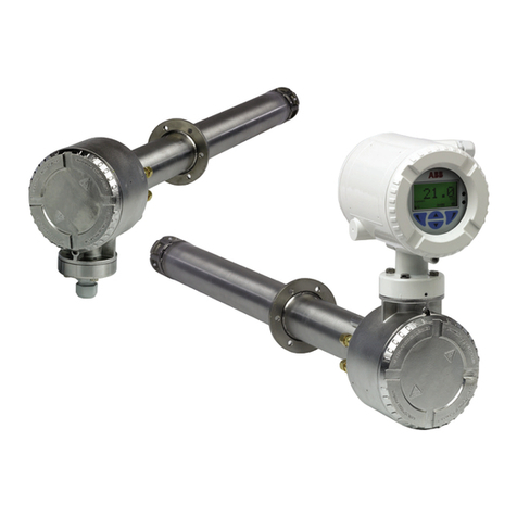
ABB AV410 User manual

Single and Dual Input Dissolved Organics Monitor
AV410, AV411, AV412, AV420 and AV422
User Guide
IM/AV4ORG_3

ABB
The Company
We are an established world force in the design and manufacture of instrumentation for industrial
process control, flow measurement, gas and liquid analysis and environmental applications.
As a part of ABB, a world leader in process automation technology, we offer customers
application expertise, service and support worldwide.
We are committed to teamwork, high quality manufacturing, advanced technology and unrivalled
service and support.
The quality, accuracy and performance of the Company’s products result from over 100 years
experience, combined with a continuous program of innovative design and development to
incorporate the latest technology.
The NAMAS Calibration Laboratory No. 0255 is just one of the ten flow calibration plants
operated by the Company, and is indicative of our dedication to quality
and accuracy.
Electrical Safety
This equipment complies with the requirements of CEI/IEC 61010-1:2001-2 'Safety Requirements for Electrical Equipment for
Measurement, Control and Laboratory Use'. If the equipment is used in a manner NOT specified by the Company, the protection
provided by the equipment may be impaired.
Symbols
One or more of the following symbols may appear on the equipment labelling:
Health and Safety
To ensure that our products are safe and without risk to health, the following points must be noted:
1. The relevant sections of these instructions must be read carefully before proceeding.
2. Warning labels on containers and packages must be observed.
3. Installation, operation, maintenance and servicing must only be carried out by suitably trained personnel and in accordance with the
information given.
4. Normal safety precautions must be taken to avoid the possibility of an accident occurring when operating in conditions of high pressure and/
or temperature.
5. Chemicals must be stored away from heat, protected from temperature extremes and powders kept dry. Normal safe handling procedures
must be used.
6. When disposing of chemicals ensure that no two chemicals are mixed.
Safety advice concerning the use of the equipment described in this manual or any relevant hazard data sheets (where applicable) may be
obtained from the Company address on the back cover, together with servicing and spares information.
Warning – Refer to the manual for instructions
Caution – Risk of electric shock
Protective earth (ground) terminal
Earth (ground) terminal
Direct current supply only
Alternating current supply only
Both direct and alternating current supply
The equipment is protected
through double insulation
Information in this manual is intended only to assist our customers in the efficient operation of our equipment. Use of this manual for
any other purpose is specifically prohibited and its contents are not to be reproduced in full or part without prior approval of the
Technical Publications Department.
EN ISO 9001:1994
Cert. No. Q05907
EN 29001 (ISO 9001)
Lenno, Italy – Cert. No. 9/90A
0255
Stonehouse, U.K.

1
Table 1.1 AV400 Series Dissolved Organics Monitor Options
rebmuNledoMrezylanArezylanAfonoitpircseDArosneSBrosneS
014VAegnaRwoLtupnIelgniS0010237–
114VAegnaRwoLtupnIlauD00102370010237
214VAegnaRhgiHdnawoLtupnIlauD00102370020237
024VAegnaRhgiHtupnIelgniS0020237–
224VAegnaRhgiHtupnIlauD00202370020237
CONTENTS
1INTRODUCTION .............................................................. 2
1.1 Introduction .............................................................. 2
1.2 Principle of Operation................................................ 2
1.3 AV400 Series Systems .............................................. 2
2OPERATION ..................................................................... 3
2.1 Powering Up the Monitor .......................................... 3
2.2 Displays and Controls ............................................... 3
2.2.1 Membrane Key Functions ............................ 3
2.3 Operating Page ......................................................... 6
2.3.1 Single Input Dissolved Organics ................... 6
2.3.2 Dual Input Dissolved Organics ..................... 7
2.3.3 Wash Function ............................................. 8
3OPERATOR VIEWS ......................................................... 9
3.1 View Set Points ......................................................... 9
3.2 View Outputs .......................................................... 10
3.3 View Hardware ....................................................... 10
3.4 View Software ......................................................... 11
3.5 View Clock .............................................................. 11
3.6 View Logbook ......................................................... 12
4SETUP ............................................................................ 14
4.1 Sensor Calibration Standard Solutions .................... 14
4.1.1 Zero Standard Solution .............................. 14
4.1.2 Span Standard Solution ............................. 14
4.1.3 Calibration Checks .................................... 14
4.2 Sensor Calibration .................................................. 15
5PROGRAMMING ........................................................... 17
5.1 Security Code ......................................................... 17
5.2 Configure Display .................................................... 18
5.3 Configure Sensors .................................................. 19
5.4 Configure Alarms .................................................... 21
5.5.1 Wash Cycle Configuration (applicable
only to Alarm 3) .......................................... 23
5.5 Configure Outputs .................................................. 25
5.6 Configure Clock ...................................................... 26
5.7 Configure Logbook ................................................. 27
5.8 Configure Security .................................................. 27
5.9 Test Outputs and Maintenance ............................... 28
6INSTALLATION .............................................................. 32
6.1 Siting Requirements ................................................ 32
6.1.1 Transmitter................................................. 32
6.1.2 Sensor ....................................................... 32
6.2 Mounting the Transmitter ........................................ 33
6.3 Installing the Sensor ................................................ 34
6.4 Installing the Optional De-bubbler ........................... 36
6.5 Electrical Connections............................................. 38
6.5.1 Relay Contact Protection and Interference
Suppression ............................................... 39
6.5.2 Cable Entry Knockouts .............................. 40
6.5.3 Access to Terminals ................................... 41
6.5.4 Connections .............................................. 42
7CALIBRATION ............................................................... 43
7.1 Factory Settings ...................................................... 43
8SENSOR MAINTENANCE ............................................. 50
8.1 Scheduled Maintenance ......................................... 50
8.2 Cleaning the Sensor ................................................ 50
8.2.1 Dismantling and Cleaning .......................... 50
8.3 Replacing the Emitter and Receiver Modules .......... 55
8.4. Adjusting the Emitter Brightness ............................ 55
9DIAGNOSTICS ............................................................... 56
9.1 Status Messages .................................................... 56
9.2 Unstable or Erratic Readings ................................... 56
10 SPARES ....................................................................... 57
SPECIFICATION .................................................................. 58
APPENDIX A REPLACING A 7320 TRANSMITTER
WITH AN AV400 .................................................................. 60

2
1INTRODUCTION
Fig. 1.1 AV400 Series Systems
1.3 AV400 Series Systems – Fig. 1.1
Note. An AV400 System is supplied factory-
configured as a matched system with each component
bearing the same serial number. If any part of a system
is replaced (transmitter or sensor[s]), a complete
factory re-calibration must be carried out – see
Section 7.
•The AV410 and AV411 low range monitors are primarily for
use in potable water applications, such as monitoring the
effectiveness of the coagulation control, THM precursor
detection and final treated water quality.
Range: 0 to 20mgl-1 C maximum.
•The AV420 and AV422 high range coagulation monitors are
designed for use in potable water treatment plants to predict
the coagulant dose to be applied to the raw water and to
detect the rise in DOC from algal bloom toxins.
Range: 0 to 100mgl-1 C maximum.
1.1 Introduction
UV
Warning. The sensor emitter module
contains a high intensity xenon strobe lamp that emits
ultraviolet (UV) radiation. This must NOT be viewed
with the naked eye and must NEVER be operated
while outside the sensor. Under normal operating
conditions, it is not possible to see the light source but,
if the sensor is dismantled with electrical power applied,
it may be possible to expose the eyes to the strobe
flash.
Many dissolved organic compounds (DOC) found commonly in
potable water absorb ultraviolet radiation. These include Humic
Acids, that gives water a characteristic yellow color, and
dissolved organics, that result in the formation of
Trihalomethanes (THMs).
The monitor is designed for use as a surrogate color monitor,
coagulation monitor/controller and to monitor for THM
precursors in potable water treatment plants.
1.2 Principle of Operation
The broad-spectrum, high intensity xenon strobe lamp, housed
in the emitter module, generates pulses of light that pass
through the sample water in the flowcell to a filtering and
detection system, contained in the receiver module. The
received light pulses are analyzed at two wavelengths; the
measurement wavelength of 254 nm and the reference
wavelength of 405 nm (at which the sample constituents of
interest do not absorb). This dual light path system provides
information that enables the measured value to be corrected for
any turbidity due to suspended matter in the sample. The
monitor is calibrated with a pure solution of a suitable organic
compound of known carbon content.
An automatic, microprocessor-controlled, dual-wiper system,
housed in the cleaner module, cleans the flowcell optical
windows periodically to ensure that the sensor remains
functional. Samples containing large solids and/or very high
concentrations of solids must be pre-filtered.
7320 100 AV400
AV4007320 200
Low Range System
High Range System

3
Fig. 2.1 Location of Controls and Displays
Fig. 2.2 Membrane Key Functions
2.1 Powering Up the Monitor
Warning. Ensure all connections are made
correctly, especially to the earth studs – see Section 6.5.
1) Ensure the input sensor(s) is (are) connected correctly.
2) Switch on the power supply to the transmitter. A start-up
screen is displayed while internal checks are performed;
then the Operating Page (Section 2.3) is displayed as the
dissolved organics measuring operation starts.
2.2 Displays and Controls – Fig. 2.1
The upper and center display lines each comprise a 41/2digit,
7-segment digital display that shows the actual value of the
measured parameter and alarm set points, followed by a
6-character dot matrix display showing the associated units.
The lower line is a 16-character dot matrix display showing
operating and programming information.
2.2.1 Membrane Key Functions – Fig. 2.2
Alarm LEDs
Upper Display Line
Lower Display Line
Membrane Keys
Menu Key
Sidescroll Key
Downscroll Key
Up Key
Down Key
1.25
Diss. Organics
10.25
mg/l C
mg/l C
Center Display Line
B – Advancing to Next Page
C – Moving Between Frames
D – Adjusting and Storing a Parameter Value
E – Selecting and Storing a Parameter Choice
A – Moving Between Menus
For majority
of frames
Frame 1
Frame 2
Frame 3
Frame 4
Page 1
Frame 1
Frame 2
Frame 3
Page 2
Advance to
next page
or
Frame 1
Frame 2
Frame 3
Page X
Frame 4
Advance to
next frame
New value is
stored automatically
Parameter Value
Adjust
Parameter X
Y
Z
Select
New value is
automatically stored
Menu 1
Menu 2
Advance to
next menu
2OPERATION

4
…2 OPERATION
Fig. 2.3A Overall Programming Chart
VIEW SETPOINTS VIEW OUTPUTS VIEW HARDWARE VIEW SOFTWARE
A1: Setpoint Analog Output 1 Sensor Type A AV400/2000 Issue
A2: Setpoint Analog Output 2 Sensor Type B
A3: Setpoint Digital Comms.
Use the Sidescroll Key to scroll through the Pages within each Menu
To CONFIG. OUTPUTS
(see Fig. 2.3B)
Use the Downscroll
Key to scroll through
the Parameters
within each Page
OPERATING PAGE
Section 2.3, Page 6 Section 3.1, Page 8 Section 3.2, Page 9 Section 3.3, Page 9 Section 3.4, Page 10 Section 3.5, Page 10 Section 3.6, Page 11
Alarms
Errors
Power
Cals
VIEW LOGBOOKVIEW CLOCK
Date 01:03:04
Time 12:00
SENSOR CAL
Section 4.2, Page 14
SECURITY CODE
Section 5.1, Page 16
CONFIG.SENSOR
Section 5.3, Page 18
Use the Menu Key
to scroll through
the Menus
Set Backlight
LED Backlight
CAL. USER CODE Calib. Sensor A
A:Fill Zero Sol.
A:#####085%#####
A:Fill Span Sol.
A:#####085%#####
A:Cal. Complete
Calib. Sensor B
B:Fill Zero Sol.
B:#####085%#####
B:Fill Span Sol.
B:#####085%#####
B:Cal. Complete
Set Language
English
CONFIG. DISPLAY
Section 5.2, Page 17
Config. Sensor A
A:Displayed Unit
A:Filter Time
A:Conv. Factor
A:Flow Alarm
A: Infer. Units
A:Clean Interval
B:Displayed Unit
B:Filter Time
B: Infer. Units
B:Conv. Factor
B:Flow Alarm
Config. Sensor B
B:Clean Interval
Config. Alarm 1
A1: Assign
A1: Type
A1: Failsafe
A1: Action
A1: Setpoint
A1: Hysteresis
A1: Delay
Config. Alarm 2
A2: Assign
A2: Type
A2: Failsafe
A2: Action
A2: Setpoint
A2: Hysteresis
A2: Delay
A3: Type
A3: Failsafe
A3: Action
A3: Setpoint
A3: Hysteresis
A3: Delay
Config. Alarm 3
A3: Assign
Section 5.4, Page 20
CONFIG.ALARMS
A: User Defined B: User Defined
Displayed only if digital communications option board fitted and PROFIBUS-DP
digital communications feature enabled – see Section 7.1
Key
Dual input analyzer only

5
Fig. 2.3B Overall Programming Chart
To
FACTORY SETTINGS
(see Section 7.1, Page 41)
Use the Sidescroll Key to scroll through the Pages within each Menu
Logbook
CONFIG. LOGBOOK
CONFIG. SERIAL
Section 5.7, Page 25
Use the Menu Key
to scroll through
the Menus
TEST/MAINTENANCE Test Outputs
Test Output 1
Test Output 2
Section 5.9, Page 26
Maintenance
Hold Outputs
A Cal.Coefficients
Org. Totals
Ref. Totals
Org. Peak
Ref. Peak
Load/Save Config
Factory Config.
User Config.
Press To AbortPress To Set
B Cal.Coefficients
Org. Totals
Ref. Totals
Org. Peak
Ref. Peak
CONFIG.OUTPUTS Config. Output 1
AO1: Assign
AO1: Range
AO1: Span Value
AO1: Default
AO1: Default Val
Config. Output 2
AO2: Assign
AO2: Range
AO2: Span Value
AO2: Default
AO2: Default Val
Section 5.5, Page 23
Use the Downscroll
Key to scroll through
the Parameters
within each Page
Section 5.6, Page 24
Set Clock?
Format dd/mm/yy
Date 01:03:04
Time 12:00
Press To AbortPress To Set
CONFIG. CLOCK
CONFIG. SECURITY Alter Sec. Code
Alter Cal. Code
Section 5.8, Page 25
Displayed only if digital communications option board fitted and PROFIBUS-DP digital communications
feature enabled (Section 7.1) – see Supplementary Manual PROFIBUS Datalink Description (IM/PROBUS)
Sensor A Outputs Sensor B Outputs
Org & Ref Signals
Org & Ref Signals
Sensor A Reading Sensor B ReadingAutomatic Time
2OPERATION…

6
…2 OPERATION
2.3 Operating Page
2.3.1 Single Input Dissolved Organics
Measured Values
Reading in inferred units, e.g. Colour (°H). For units available, refer to Inferred Units in
Section 5.3.
Concentration of dissolved organics in mgl–1.
Note. If Lamp Disabled (see below) is set to Yes, Lamp Disabled is shown in the lower
display line and no values are displayed.
Disabling the Lamp
UV
Warning. Disable the lamp before performing any maintenance on the sensor –
see also Warning on page 2.
If Yes is selected, Lamp Disabled is shown in the lower display line.
Manual Cleaning
Select Yes to initiate the sensor cleaning system.
See Section 3.1.
See Section 4.2.
A3: Type set to Wash (Section 5.4.) – See Section 2.3.3.
A3: Type not set to Wash (Section 5.4.) – Return to the top of the page.
Diss. Organics
1.25
H
10.25
mg/l C
Manual Clean
Sen. A
-----
VIEW SETPOINTS
SENSOR CAL
WASH FUNCTION
Lamp Disabled
Sen. A
-----
Yes
No
Yes
No
Diss. Organics

7
…2.3 Operating Page
2.3.2 Dual Input Dissolved Organics
Measured Values in Inferred Units
Sensor A reading in inferred units, e.g. Colour (°H). For units available, refer to Inferred Units
in Section 5.3.
Sensor B reading in inferred units.
Note. If Lamp Disabled (see below) is set to Yes, Lamp Disabled is shown in the lower
display line and no values are displayed.
Equivalent Values in mgl–1
Sensor A.
Sensor B.
Note. If Lamp Disabled (see below) is set to Yes, Lamp Disabled is shown in the lower
display line and no values are displayed.
Disabling the Lamp – Sensor A
UV
Warning. Disable the lamp before performing any maintenance on the sensor –
see also Warning on page 2.
If Yes is selected, Lamp Disabled is shown in the lower display line.
Disabling the Lamp – Sensor B
UV
Warning. Disable the lamp before performing any maintenance on the sensor –
see also Warning on page 2.
If Yes is selected, Lamp Disabled is shown in the lower display line.
Manual Cleaning – Sensor A
Select Yes to initiate the Sensor A cleaning system.
Manual Cleaning – Sensor B
Select Yes to initiate the Sensor B cleaning system.
See Section 3.1.
See Section 4.2.
A3: Type set to Wash (Section 5.4.) – See Section 2.3.3.
A3: Type not set to Wash (Section 5.4.) – Return to the top of the page.
Diss. Organics
1.25
H
1.25
H
Diss. Organics
10.25
mg/l C
10.25
mg/l C
Manual Clean
Sen. B
-----
VIEW SETPOINTS
SENSOR CAL
Lamp Disabled
Sen. A
-----
Yes
No
Yes
No
Lamp Disabled
Sen. B
-----
Yes
No
Manual Clean
Sen. A
-----
Yes
No
WASH FUNCTION
Diss. Organics
2OPERATION

8
…2.3 Operating Page
2.3.3 Wash Function
Note. The Wash function is available only if A3: Type is set to Wash – see Section 5.5.
Wash Function
Off –Wash function off. Lower display line of Operating Page shows
WASH INHIBITED.
On –Wash function controlled automatically. Lower display line of Operating Page
shows WASH IN PROGRESS.
Manual –Enables wash function to be initiated manually – see below.
Note. Set Wash Function to Off before removing the sensor from the process.
See Section 3.1.
See Section 4.1.
Wash Function set to Manual – see below.
Wash Function not set to Manual. The display returns to the top of the
Operating Page.
Press to Wash (Manual Wash only)
Press to Wash and Press to Abort are shown alternately on the lower display line.
Press the key to initiate the wash cycle. The display returns to the top of
the Operating Page and the lower display line shows WASH IN PROGRESS until
the wash cycle is completed. The Wash Function selection reverts to the one
that was set before Manual was selected.
Press the key to abort the wash cycle. The display returns to the top of
the Operating Page.
VIEW SETPOINTS
SENSOR CAL.
Wash Function
-----
Manual
On
Off
-----
Press To Wash
Press To Abort
Press To Wash
Diss. Organics
WASH IN PROGRESS
Diss. Organics
…2 OPERATION

9
3OPERATOR VIEWS
3.1 View Set Points
View Set Points
This page shows alarm set points. The value of each of the set points is shown, together
with the name of the parameter it's assigned to.
Alarm assignments, set point values and relay/LED actions are programmable – see
Section 5.4. Those shown in the following frames are examples only.
Alarm 1 Set Point
Alarm set point in inferred units, e.g. Colour (H). For units available, refer to Inferred Units
in Section 5.3. The units displayed alternate between the inferred units selected (see
Section 5.3) and the alarm assignment indication (Sen. A [or Sen. B – dual input monitors
only]) – see Section 5.4.
Alarm set point in units selected for display – see Displayed Units in Section 5.3.
Alarm 2 Set Point
Alarm set point assignment – see Section 5.4.
Alarm set point in units selected for display – see Displayed Units in Section 5.3.
Note. Inferred Units for Sensor B (dual input monitors only) set to None –see Section 5.3.
Alarm 3 Set Point
See Section 3.2.
See Section 4.2.
10.00
mg/l C
A1: Setpoint
4.20
Sen. A
Sen. B
VIEW SETPOINTS
-----
10.25
mg/l C
A2: Setpoint
Sen. B
3.500
mg/l C
A3: Setpoint
VIEW OUTPUTS
SENSOR CAL
VIEW SETPOINTS

10
3.2 View Outputs
Theoretical Analog Output
There are two analog outputs that are assigned automatically depending on monitor
configuration. On a single input monitor, both are assigned to Sensor A. On a dual input
monitor, Output 1 is assigned to Sensor A and Output 2 is assigned to Sensor B.
Live current output value being retransmitted.
Current output shown as a percentage of full scale for the output range set in CONFIG.
OUTPUTS – see Section 5.5.
See Section 3.3.
See Section 4.2.
Advance to analog output 2.
3.3 View Hardware
Sensor Type A
Displays the sensor type selected for the Sensor A input in the Factory Settings page – see
Section 7.1.
7320 100 –Low Range (0 to 20mgl-1 C)
7320 200 –High Range (0 to 100mgl-1 C)
Sensor Type B – Dual input monitors only
Displays the sensor type selected for the Sensor B input in the Factory Settings page – see
Section 7.1.
Digital Communications Option Board
Note. Displayed only if the digital communications option board is fitted.
Displays the communications type enabled in the Factory Settings page – see Section 7.1.
See Section 3.4.
See Section 4.2.
102.0
%
Analog Output 1
20.40
mA
VIEW OUTPUTS
-----
VIEW HARDWARE
SENSOR CAL
Analog Output 2
100
100
7320
Sensor Type A
VIEW HARDWARE
-----
7320
Sensor Type B
UV
UV
Digital Comms.
-----
Pb DP
VIEW SOFTWARE
SENSOR CAL
VIEW HARDWARE
…3 OPERATOR VIEWS

11
3OPERATOR VIEWS…
3.4 View Software
Issue
Shows the version number of the software.
See Section 3.5.
See Section 4.2.
3.5 View Clock
Date
Shows the current date.
Time
Shows the current time.
Logbook set to On (Section 5.7) – see Section 3.6.
Logbook set to Off (Section 5.7) – see Section 2.3.
See Section 4.2.
1.0
AV400/2000 Issue
VIEW SOFTWARE
-----
VIEW CLOCK
SENSOR CAL
VIEW SOFTWARE
-----
Date
17:03
:04
VIEW CLOCK
-----
-----
Time 10:48
VIEW LOGBOOK
SENSOR CAL
VIEW CLOCK Diss. Organics

12
…3 OPERATOR VIEWS
3.6 View Logbook
Note. The View Logbook function is available only if Logbook is set to On – see Section 5.7.
The logbook stores data entries for alarm events, sensor errors, power failures and sensor
calibrations.
View Logbook
Use the and keys to access the Alarms logbook.
Note. If no entries are stored in the Alarms logbook, the display shows No More Entries.
Alarms
The Alarms logbook contains up to 10 entries (entry 1 is the most recent), each comprising
an alarm number, alarm state (On or Off), and the date/time of the occurrence.
Operating Page – see Section 2.3.
See Section 4.2.
Advance to entries 2 to 10.
Note. If no more entries are stored, the display shows No More Entries.
View Logbook
Use the and keys to access the Errors logbook.
Note. If no entries are stored in the Errors logbook, the display shows No More Entries.
Errors
The Errors logbook contains up to 5 entries (entry 1 is the most recent), each comprising
the sensor letter, error number, and the date/time of the occurrence.
Operating Page – see Section 2.3.
See Section 4.2.
Advance to entries 2 to 5.
Note. If no more entries are stored, the display shows No More Entries.
-----
02:03:04 15:17
VIEW LOGBOOK
-----
Diss. Organics
SENSOR CAL
2A1
-----
VIEW LOGBOOK
1
Cals
Power
Errors
Alarms
A1
On
-----
-----
02:03:04 16:44
Diss. Organics
SENSOR CAL
2Sen. A
VIEW LOGBOOK
1
Sen. A
Alarms
Cals
Power
Errors

13
3OPERATOR VIEWS
…3.6 View Logbook
View Logbook
Use the and keys to access the Power logbook.
Note. If no entries are stored in the Power logbook, the display shows No More Entries.
Power
The Power logbook contains up to 2 entries (entry 1 is the most recent), each comprising
the power state (On or Off), and the date/time of the occurrence.
Operating Page – see Section 2.3.
See Section 4.2.
Advance to entry 2.
Note. If no more entries are stored, the display shows No More Entries.
View Logbook
Use the and keys to access the Cals logbook.
Note. If no entries are stored in the Cals logbook, the display shows No More Entries.
Calibration
The Cals logbook contains up to 5 entries (entry 1 is the most recent), each comprising
3 frames. Frame 1 contains the entry number, sensor letter, calibration type (Z = Zero,
S = Span, ZS = Zero and Span) and the date/time of the occurrence.
Frames 2 and 3 contain the raw outputs from the sensor for both the Zero and Span
solutions. These values equate to the percentage light transmission through the standard
solutions.
Operating Page – see Section 2.3.
See Section 4.2.
Advance to entries 2 to 6 for single input monitors.
Advance to entries 2 to 3 for sensor A on dual input monitors.
Advance to entries 4 to 6 for sensor B on dual input monitors.
Note. If no more entries are stored, the display shows No More Entries.
-----
12:03:04 11:34
Diss. Organics
SENSOR CAL
2
-----
VIEW LOGBOOK
1
Off
Errors
Alarms
Cals
Power
Diss. Organics
-----
12:03:04 18:56
-----
VIEW LOGBOOK
1
Sen. A
ZS Cal
Ref Totals
SENSOR CAL
2Sen.A
99.9
Zero A
Span A
98.3
Power
Errors
Alarms
Cals
30.5
Org Totals
99.2
Zero A
Span A
2Sen.A
4Sen.B

14
4.1 Sensor Calibration Standard Solutions
UV absorption is a non-specific, aggregate measurement of
organic carbon concentration therefore true standards are not
available. A standard solution, made from potassium hydrogen
phthalate, is used for calibration purposes and the monitor
produces readings in units of mgl–1 of carbon defined against this
calibration standard.
Note. Clean the flowcell internally (see Section 8)
before calibration to ensure that the standard solutions,
particularly the zero standard, are not contaminated
with organic material that may be present inside the
flowcell.
4.1.1 Zero Standard Solution
High purity water is used for the zero standard solution and must
be as fresh as possible. If storage is unavoidable, use a glass
container to prevent contamination. Some plastics, for example
polythene and polypropylene, may be acceptable, but
regardless of material, the container must be meticulously clean
and kept solely for the purpose of storing the zero standard
solution.
Note. The high purity water used for the zero solution
and for diluting the span standard solution must contain
less than 50µgl–1 TOC. It is recommended that the
water is obtained from purification systems comprising
reverse osmosis and de-ionization units but freshly
distilled water can also be used. De-ionized water is not
recommended as it often contains significant levels of
organics.
4.1.2 Span Standard Solution
The span standard solution is prepared from potassium hydrogen
phthalate (KOOC.C6H4.COOH, carbon content = 47.05 %),
Analytical Reagent grade and high purity water.
To prepare a 1000mgl–1C carbon stock standard solution:
1. Dry 2.125±0.005g of potassium hydrogen phthalate at
120°C for 2 hours.
2. Dissolve the dried potassium hydrogen phthalate in
500ml high purity water.
3. make up to 1 litre in a volumetric flask.
The solution may be stored in a glass bottle in a refrigerator,
without freezing, for up to 12 months.
Working standard solutions for system calibration must be
freshly prepared from the stock standard when required. Dilute
the stock solution with high purity water. Discard the working
standard solution after use.
7320 100 Low Range Sensor – 10mgl-1C:
Dilute 10ml of the stock standard solution to 1 litre high purity
water in a volumetric flask.
7320 200 High Range Sensor – 50mgl-1C:
Dilute 50ml of the stock standard solution to 1 litre high purity
water in a volumetric flask.
4.1.3 Calibration Checks
The sensor's emitter module contains an optical system with
very stable electronics that eliminate electronic drift, therefore,
routine calibration is normally unnecessary. However, it may be
necessary to check system accuracy, particularly after cleaning
the flowcell.
A calibration check is carried out by filling the flowcell with the
Zero and Span standard solutions and observing the readings in
the Operating Page – see Section 2.3.
The solutions are poured in from the top of the flowcell.
7320 100 Low Range Sensor:
Remove the wiper module, fill the flowcell and refit the wiper
module.
7320 200 High Range Sensor:
Remove the filler plug on top of the flowcell and use the
funnel provided.
4SETUP

15
4SETUP
4.2 Sensor Calibration
Sensor Calibration
Sensor Calibration Security Code
Note. This frame is displayed only if Alter Cal. Code is not set to zero – see Section 5.8.
Enter the required code number (between 0000 and 19999) to gain access to the sensor
calibration pages. If an incorrect value is entered, access to the calibration pages is
prevented and the display reverts to the SENSOR CAL. frame.
Calibrate Sensor A
Note. A full calibration comprises a zero and a span calibration. However, it is possible to
carry out zero and span calibrations independently by aborting the one that is not required
(press the key to initiate the calibration and press it again before the calibration is
complete). If either calibration is aborted, A:Cal Incomplete is shown on the lower display
line (see next page). The Cals logbook records the calibration type as zero (Z), span (S) or
both (ZS) – see Section 3.6, page 12.
Sensor B calibration (dual input monitors only) is identical to Sensor A
calibration.
Single input monitors only – return to main menu.
Alter Sec. Code not set to zero (Section 5.8) – see Section 5.1.
Alter Sec. Code set to zero (Section 5.8) – see Section 5.2.
Zero Calibration
Fill the flowcell with high purity water – see Section 4.1.1.
Press the key to initiate calibration.
Note. If the key is pressed again at any time before zero calibration is complete, the
display advances automatically to the A:Fill Span Sol. frame.
Raw Output from Sensor
Organics total signal These values equate to the percentage light transmission
through the sample.
Reference total signal
As calibration proceeds, a progress indicator appears in the lower display line. After 3
minutes, the lower display line shows 100%, the display then advances
automatically to the next frame.
Continued on next page.
Calib. Sensor A
-----
SENSOR CAL
-----
CAL. USER CODE
0000
Calib. Sensor B
SENSOR CAL
A:Fill Zero Sol.
0.0
mg/l C
100%
100.0
0.00
R100.0
A:Fill Span Sol.
SECURITY CODE
CONFIG. DISPLAY

16
…4.2 Sensor Calibration
Span Calibration
Fill the flowcell with the required span standard calibration solution – see Section 4.1.2.
Press the key to initiate calibration.
Note. If the key is pressed again at any time before span calibration is complete,
A:Cal Incomplete is shown on the lower display line (see below).
Raw Output from Sensor
Organics total signal These values equate to the percentage light transmission
through the sample.
Reference total signal
As calibration proceeds, a progress indicator appears in the lower display line. After 3
minutes, the lower display line shows 100%, the display then advances
automatically to the next frame.
Calibration Completed
A message is displayed at the end of calibration:
A:Cal Complete –calibration successful
A:Cal Incomplete –zero and/or span calibration aborted
Sensor B calibration (dual input monitors only) is identical to Sensor A
calibration.
Single input monitors only – return to main menu.
Alter Sec. Code not set to zero (Section 5.8) – see Section 5.1.
Alter Sec. Code set to zero (Section 5.8) – see Section 5.2.
…4 SETUP
A:Fill Span Sol.
50.0
mg/l C
50.0
100%
25.0
50.0
mg/l C
R100.0
A:Cal. Complete
50.0
SECURITY CODE
CONFIG. DISPLAY
Calib. Sensor A Calib. Sensor B
SENSOR CAL
mg/l C

17
5PROGRAMMING
5.1 Security Code
Note. This frame is displayed only if Alter Sec. Code is not set to zero – see Section 5.8.
Enter the required code number (between 0000 and 19999) to gain access to the
configuration pages. If an incorrect value is entered, access to the configuration pages is
prevented and the display reverts to the Operating Page – see Section 2.3.
See Section 5.2.
SECURITY CODE
0000
CONFIG. DISPLAY

18
5.2 Configure Display
Set Language
Sets the language to be used on all displays.
Language
Use the and keys to select the required language.
Set Up Display Backlight
Backlight
Use the and keys to select the required backlight option:
On –Backlight is always on.
Auto. –Backlight comes on at each button press and switches off one minute after
the last button press.
Return to main menu.
See Section 5.3.
…5 PROGRAMMING
CONFIG. DISPLAY
-----
Set Language
-----
-----
LED Backlight
-----
Set Backlight
-----
Auto.
On
CONFIG. DISPLAY
CONFIG. SENSOR
Set Backlight
Set Language
English
Deutsch
Francais
Espanol
Italiano
This manual suits for next models
4
Table of contents
Other ABB Monitor manuals

ABB
ABB 8242 User manual

ABB
ABB Endura AZ20 series Operating manual

ABB
ABB CL Series Instructions for use

ABB
ABB CEM11-FBP.35 User manual

ABB
ABB M2238 Series User manual

ABB
ABB 8232 User manual

ABB
ABB Endura AZ25 Series User manual

ABB
ABB Industrial enabled Analyzer 9437 User manual

ABB
ABB 7835 User manual

ABB
ABB 9438 User manual