ABB 7835 User manual

User Guide IM/7835–EN Rev. P
7835
Hydrazine Monitor

The Company
We are an established world force in the design and manufacture of measurement
products for industrial process control, flow measurement, gas and liquid analysis and
environmental applications.
As a part of ABB, a world leader in process automation technology, we offer customers
application expertise, service and support worldwide.
We are committed to teamwork, high quality manufacturing, advanced technology and
unrivalled service and support.
The quality, accuracy and performance of the Company’s products result from over 100
years experience, combined with a continuous program of innovative design and
development to incorporate the latest technology.
EN ISO 9001:2000
Cert. No. Q 05907
EN 29001 (ISO 9001)
Lenno, Italy – Cert. No. 9/90A
Stonehouse, U.K.

7835
Hydrazine Monitor Contents
IM/7835–EN Rev. P 1
Contents
1 Safety ...............................................................................2
1.1 Health & Safety ........................................................2
1.2 Electrical Safety – CEI/IEC 61010-1:2001-2 .............2
1.3 Symbols – CEI/IEC 61010-1:2001-2 ........................2
1.4 Product Recycling Information .................................3
1.5 Product Disposal .....................................................3
1.6 Restriction of Hazardous Substances (RoHS) ..........3
1.7 Chemical Reagents .................................................3
1.8 Safety Precautions ...................................................3
1.9 Safety Conventions ..................................................3
1.10 Safety Recommendations ........................................4
1.11 Service and Repairs .................................................4
1.12 Potential Safety Hazards ......................................... 4
2 Introduction ..................................................................... 5
2.1 General ....................................................................5
2.2 Sensor Unit ..............................................................5
2.3 Transmitter Unit .......................................................5
3 Mechanical Installation ...................................................6
3.1 Unpacking ...............................................................6
3.2 End of Life Disposal .................................................6
3.2.1 Transmitter ...................................................6
3.2.2 Sensor and Sensor
(Wet Section Assembly) ................................6
3.3 Cleaning ...................................................................6
3.4 Installation Conditions ..............................................6
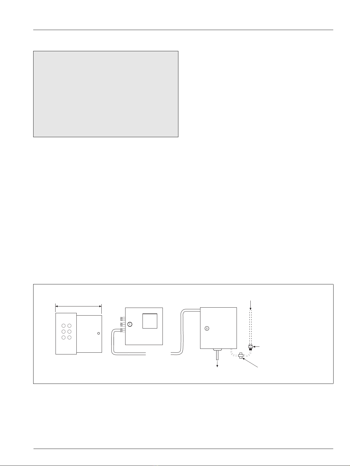
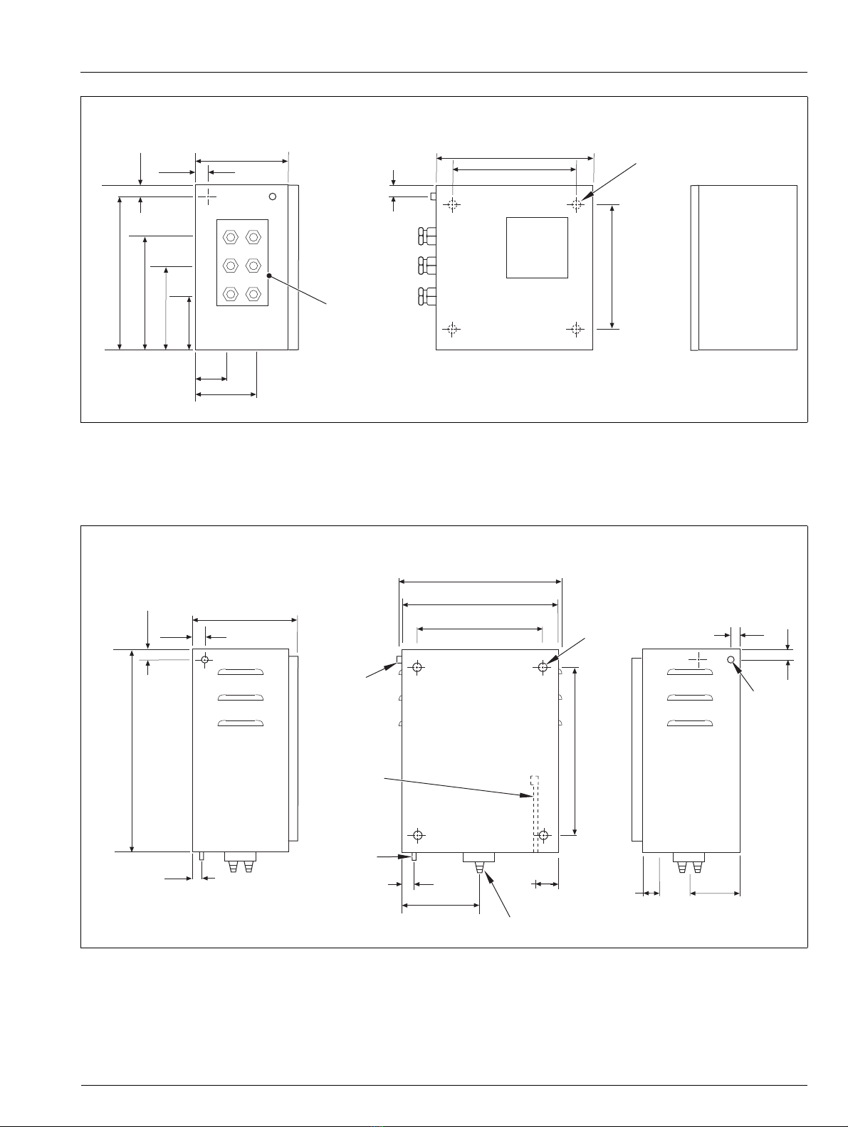
3.5 Overall Dimensions ...................................................6
3.5.1 Transmitter Unit ............................................ 6
3.5.2 Sensor Unit ...................................................7
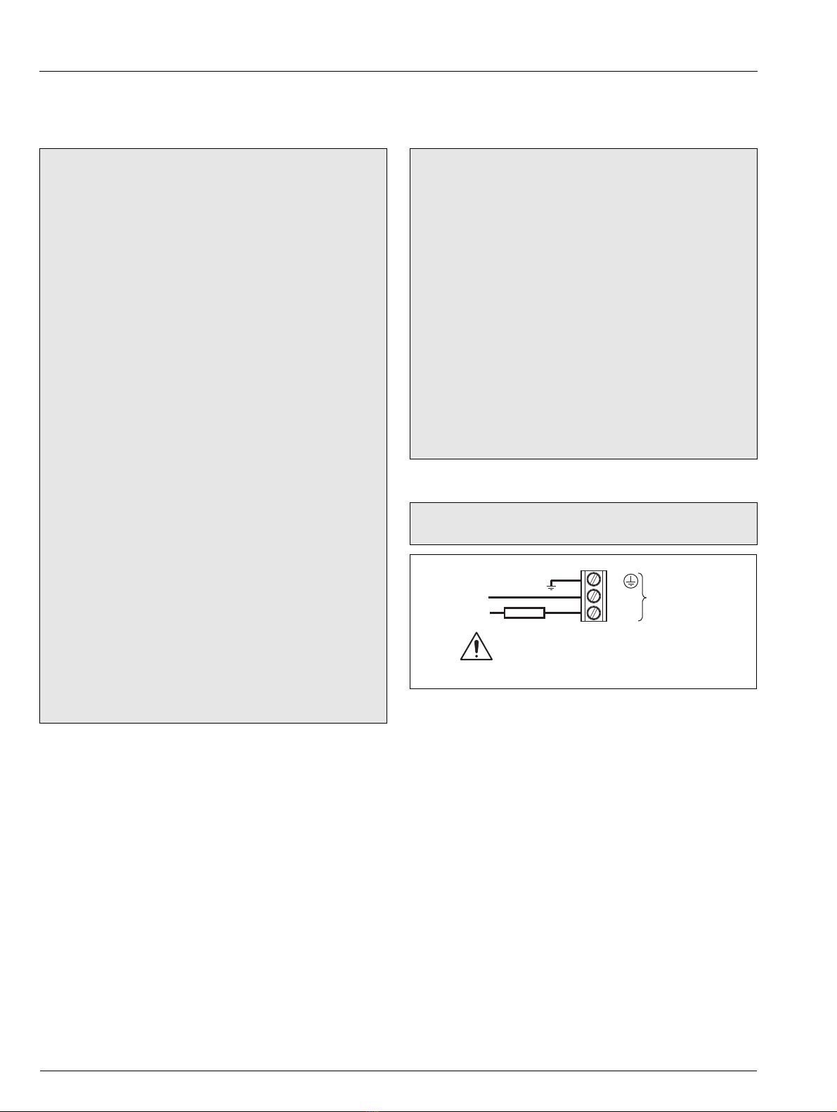
4 Electrical Installation .......................................................8
4.1 Electrical Safety ........................................................8
4.1.1 Power Supply Connections ..........................8
4.2 Transmitter Unit – Access to Terminals ....................9
4.3 Transmitter Unit –
Cable Gland Entries and Connections ......................9
4.4 Transmitter Unit – Ancillary Equipment ...................10
4.4.1 Recorders ................................................... 10
4.4.2 Range Indication .........................................10
4.5 Sensor Unit – Access to Terminals .........................10
4.6 Sensor Unit – Cable Gland Entries
and Connections ....................................................11
4.7 Sensor Unit – Sample Requirements ......................12
4.8 Sensor Unit – External Pipe Connections ...............12
4.8.1 Inlet Pipe .....................................................12
4.8.2 Drain Pipe ...................................................12
5 Commissioning .............................................................13
5.1 Start-Up .................................................................13
5.2 Sensor Unit ............................................................13
5.3 Setting Flowrates ..................................................13
5.3.1 Standard Solution Flowrate .........................14
5.3.2 Sample Flowrate ........................................ 14
5.3.3 Sample Temperature .................................15
6 Programming ................................................................ 16
6.1 Operator Page and Keys ....................................... 16
6.1.1 Access Level and Entering Passwords .................. 16
6.2 Menus ................................................................... 17
6.2.1 Calibrate .................................................... 17
6.2.2 Device Setup .............................................. 17
6.2.3 Input/Output ............................................. 18
6.2.4 Device Info ................................................. 18
7 Calibration ..................................................................... 19
7.1 Calibrating the System – General Tasks ................. 19
7.2 Sensor Calibration ................................................. 19
7.3 Setting the Standard Solution Value ....................... 19
7.4 Restoring Calibration Defaults ................................ 19
8 Troubleshooting ............................................................ 20
8.1 Diagnostics Classification Codes .......................... 20
8.2 Diagnostics Messages .......................................... 20
9 Maintenance ................................................................ 21
9.1 Chemical Solutions ................................................ 21
9.1.1 Reagent Solution – 5m (20% W/V) .................
Sodium Hydroxide ...................................... 21
9.1.2 Standard Solution ...................................... 21
9.2 Scheduled Servicing .............................................. 21
9.2.1 Weekly ....................................................... 21
9.2.2 Six-Monthly ................................................ 21
9.2.3 Yearly ......................................................... 22
9.3 Shut-down Procedures .......................................... 23
9.3.1 Sensor Unit ................................................ 23
9.3.2 Transmitter Unit .......................................... 23
9.4 Unscheduled Servicing .......................................... 24
9.4.1 Monitor Malfunction ................................... 24
9.4.2 Calibration Fail Alarm .................................. 24
9.4.3 Cleaning The Platinum Anode and
Sensor Ceramic ......................................... 25
9.4.4 Sensor Check ............................................ 25
9.4.5 Refurbishing The Sensor ............................ 25
9.4.6 Simple Electronic Check ............................ 26
10 Spares List .................................................................... 27
10.1 Refurbishment Spares ........................................... 27
10.2 Strategic Spares .................................................... 27
11 Specification ................................................................. 28

7835
Hydrazine Monitor 1 Safety
2IM/7835–EN Rev. P
1 Safety
Information in this manual is intended only to assist our
customers in the efficient operation of our equipment. Use of
this manual for any other purpose is specifically prohibited and
its contents are not to be reproduced in full or part without prior
approval of the Technical Publications Department.
1.1 Health & Safety
1.2 Electrical Safety – CEI/IEC 61010-1:2001-2
This equipment complies with the requirements of CEI/IEC
61010-1:2001-2 'Safety Requirements for Electrical Equipment
for Measurement, Control and Laboratory Use' and complies
with US NEC 500, NIST and OSHA.
If the equipment is used in a manner NOT specified by the
Company, the protection provided by the equipment may be
impaired.
1.3 Symbols – CEI/IEC 61010-1:2001-2
One or more of the following symbols may appear on the
equipment labelling:
Health and Safety
To ensure that our products are safe and without risk to
health, the following points must be noted:
The relevant sections of these instructions must be
read carefully before proceeding.
Warning labels on containers and packages must be
observed.
Installation, operation, maintenance and servicing
must only be carried out by suitably trained personnel
and in accordance with the information given.
Normal safety precautions must be taken to avoid the
possibility of an accident occurring when operating in
conditions of high pressure and/or temperature.
Chemicals must be stored away from heat, protected
from temperature extremes and powders kept dry.
Normal safe handling procedures must be used.
When disposing of chemicals ensure that no two
chemicals are mixed.
Safety advice concerning the use of the equipment
described in this manual or any relevant Material Safety
Data Sheets (where applicable) may be obtained from the
Company address on the back cover, together with
servicing and spares information.
Protective earth (ground) terminal.
Functional earth (ground) terminal.
Direct current supply only.
Alternating current supply only.
Both direct and alternating current supply.
The equipment is protected through double
insulation.
This symbol, when noted on a product, indicates a
potential hazard which could cause serious
personal injury and/or death.
The user should reference this instruction manual
for operation and/or safety information.
This symbol, when noted on a product enclosure or
barrier, indicates that a risk of electrical shock
and/or electrocution exists and indicates that only
individuals qualified to work with hazardous
voltages should open the enclosure or remove the
barrier.
This symbol indicates that the marked item can be
hot and should not be touched without care.
This symbol indicates the presence of devices
sensitive to electrostatic discharge and indicates
that care must be taken to prevent damage to
them.
This symbol identifies a risk of chemical harm and
indicates that only individuals qualified and trained
to work with chemicals should handle chemicals or
perform maintenance on chemical delivery systems
associated with the equipment.
This symbol indicates the need for protective eye
wear.
This symbol indicates the need for protective hand
wear.
Electrical equipment marked with this symbol may
not be disposed of in European public disposal
systems. In conformity with European local and
national regulations, European electrical equipment
users must now return old or end-of-life equipment
to the manufacturer for disposal at no charge to the
user.
Products marked with this symbol indicates that the
product contains toxic or hazardous substances or
elements. The number inside the symbol indicates
the environmental protection use period in years.

7835
Hydrazine Monitor 1 Safety
IM/7835–EN Rev. P 3
1.4 Product Recycling Information
1.5 Product Disposal
1.6 Restriction of Hazardous Substances (RoHS)
1.7 Chemical Reagents
1.8 Safety Precautions
Please read the entire manual before unpacking, setting up, or
operating this instrument.
Pay particular attention to all warning and caution statements.
Failure to do so could result in serious injury to the operator or
damage to the equipment.
To ensure the protection provided by this equipment is not
impaired, do not use or install this equipment in any manner
other than that which is specified in this manual.
1.9 Safety Conventions
Electrical equipment marked with this symbol
may not be disposed of in European public
disposal systems after 12 August 2005. In
conformity with European local and national
regulations (EU Directive 2002/96/EC), European
electrical equipment users must now return old
or end-of-life equipment to the manufacturer for
disposal at no charge to the user.
Note. For return for recycling, please contact the
equipment manufacturer or supplier for instructions on how
to return end-of-life equipment for proper disposal.
Note. The following only applies to European customers.
ABB is committed to ensuring that the risk of
any environmental damage or pollution caused
by any of its products is minimized as far as
possible. The European Waste Electrical and
Electronic Equipment (WEEE) Directive
(2002/96/EC) that came into force on August
13 2005 aims to reduce the waste arising from
electrical and electronic equipment; and
improve the environmental performance of all
those involved in the life cycle of electrical and
electronic equipment.
In conformity with European local and national
regulations (EU Directive 2002/96/EC stated
above), electrical equipment marked with the
above symbol may not be disposed of in
European public disposal systems after 12
August 2005.
The European Union RoHS Directive and
subsequent regulations introduced in member
states and other countries limits the use of six
hazardous substances used in the
manufacturing of electrical and electronic
equipment. Currently, monitoring and control
instruments do not fall within the scope of the
RoHS Directive, however ABB has taken the
decision to adopt the recommendations in the
Directive as the target for all future product
design and component purchasing. .
RoHS
Warning. To familiarize yourself with handling precautions,
dangers and emergency procedures, always review the
Material Safety Data Sheets prior to handling containers,
reservoirs, and delivery systems that contain chemical
reagents and standards. Protective eye wear and protective
hand wear. is always recommended when contact with
chemicals is possible.
Warning. In this manual, a warning is used to indicate a
condition which, if not met, could cause serious personal
injury and/or death. Do not move beyond a warning until all
conditions have been met.
If a warning sign appears on the instrument itself, refer to
Precautionary Labels – UL Certification and Electrical Safety
– CEI/IEC 61010-1:2001-2 for an explanation.
Caution. A caution is used to indicate a condition which, if
not met, could cause minor or moderate personal injury
and/or damage to the equipment. Do not move beyond a
caution until all conditions have been met.
Note. A note is used to indicate important information or
instructions that should be considered before operating the
equipment.

7835
Hydrazine Monitor 1 Safety
4IM/7835–EN Rev. P
1.10 Safety Recommendations
For safe operation, it is imperative that these service instructions
be read before use and that the safety recommendations
mentioned herein be scrupulously respected. If danger warnings
are not heeded to, serious material or bodily injury could occur.
1.11 Service and Repairs
Other than the serviceable items listed in Section 10, page 27,
none of the instrument's components can be serviced by the
user. Only personnel from ABB or its approved representative(s)
is (are) authorized to attempt repairs to the system and only
components formally approved by the manufacturer should be
used. Any attempt at repairing the instrument in contravention of
these principles could cause damage to the instrument and
corporal injury to the person carrying out the repair. It renders
the warranty null and void and could compromise the correct
working of the instrument and the electrical integrity or the CE
compliance of the instrument.
If you have any problems with installation, starting, or using the
instrument please contact the company that sold it to you. If this
is not possible, or if the results of this approach are not
satisfactory, please contact the manufacturer's Customer
Service
1.12 Potential Safety Hazards
The following potential safety hazards are associated with
operating the analyzer:
Electrical (line voltage)
Potentially hazardous chemicals
Warning. The installation of the instrument should be
performed exclusively by personnel specialized and
authorized to work on electrical installations, in accordance
with relevant local regulations.
Caution. This equipment has been tested and found to
comply with the limits for Class A digital device, pursuant to
Part 15 of the FCC Rules. These limits are designed to
provide reasonable protection against harmful interference
when the equipment is operated in a commercial
environment. This equipment generates, uses, and can
radiate radio frequency energy and, if not installed and used
in accordance with this instruction manual, may cause
harmful interference to radio communications. Operation of
this equipment in a residential area is likely to cause harmful
interference in which case the user is required to correct the
interference at his own expense.

7835
Hydrazine Monitor 2Introduction
IM/7835–EN Rev. P 5
2Introduction
2.1 General
The 7835 Hydrazine Monitor uses an electro-chemical cell to
measure the amount of hydrazine in boiler water. The
information provided by the monitor can be used to avoid
expensive overdosing of hydrazine or more costly damage to
boiler plant due to the under-dosing of hydrazine.
The 7835 is an accurate reliable monitor providing trouble-free
operation and requiring a minimum of routine maintenance. It
measures hydrazine over two ranges: 0 to 100 µg kg-1 and 0 to
1000 µg kg-1 – the ranges are selected manually or, if required,
switched by the monitor automatically.
The monitor is housed in 2, lockable steel cases consisting of a
liquid handling section (sensor unit) and an electronics section
(transmitter unit). The electronic case is protected to IP55 and
can be separated from the liquid handling section by up to
100m (325 ft).
2.2 Sensor Unit
The liquid handling section contains a constant-head unit
feeding sample to a sensor that can be refurbished. Reagent
solution to raise the pH of the sample is added via a
micro-porous disc. During the calibration sequence, a solenoid
valve blocks the flow of sample that diverts to the drain and
allows flow of the standard solution. Reagent and standard
solutions are held in containers with transparent ends, mounted
inside the sensor unit case.
2.3 Transmitter Unit
Operation and programming of the 7835 is via 4 keys and a
digital display located on the front of the transmitter.
In operation, the transmitter can display measured hydrazine
(µg kg-1) and the sample temperature. Set-up of alarm,
retransmission and calibration parameters is achieved in
programming mode, where key parameters are protected by
security codes.
Hydrazine values can be retransmitted to remote equipment
using the retransmission output facility. The values retransmitted
are set automatically to the range selected.
Remote alarm indication is provided by 2 relay outputs. Relays
are programmed to activate when the hydrazine level moves
either above or below a pre-defined trip point.
Remote range indication is provided by 2 relay outputs. The low
range relay is active when the range selected is 0 to 100 µg kg-1
and the high range relay is active when the range selected is 0
to 1000 µg kg-1. In automatic mode the range relays are
activated automatically.
2 Further relay outputs are available to indicate when a
calibration is in progress and if the last calibration failed.
The transmitter unit is provided with 6 cable glands fitted to the
gland plate on the left hand side of the case.
Warning.
Read all relevant sections of this guide before
configuring the system or modifying system
parameters.
Install and use this equipment as detailed in this
guide. Install and use associated equipment in
accordance with the relevant national and local
standards.
System configuration must be carried out only by
users or personnel with approved access rights (user
privileges).
Dimensions in mm (in.)
Fig. 2.1 System Layout
Transmitter unit with door open
490 (19.3) Transmitter Unit Sample
Input
Up to 100 m
(328 ft)
Suggested Installation Layout
Sensor Unit
Drain
0216–403 Inlet Valve with
1/4in. Swagelock Fittings
0216–404 Sample Filter with
1/4in. Swagelock Fittings

7835
Hydrazine Monitor 3 Mechanical Installation
6IM/7835–EN Rev. P
3 Mechanical Installation
3.1 Unpacking
3.2 End of Life Disposal
3.2.1 Transmitter
The transmitter unit does not contain any substance that causes
undue harm to the environment and must be disposed of in
accordance with the Directive on Waste Electrical and Electronic
Equipment (WEEE). It must not be disposed of in Municipal
Waste Collection.
3.2.2 Sensor and Sensor (Wet Section Assembly)
ABB recommend returning the sensor back to the Company for
safe disposal, preferably with the electrolyte/filling solution
cleaned out before dispatch.
The sensor wet section assembly must be emptied, cleaned
and disposed of in accordance with the Directive on Waste
Electrical and Electronic Equipment (WEEE).
3.3 Cleaning
Clean the transmitter and sensor units using warm water and a
mild detergent only. Do not hose down the sensor unit.
3.4 Installation Conditions
Mount both units in a clean, vibration-free environment, avoiding
direct radiant heat, sunlight and draughts. Avoid areas likely to
have contaminating gases, particularly chlorine.
Mount the sensor no more than 10 m (30 ft.) from any
associated sample cooler – see Section 4.7, page 12. The
transmitter can be mounted up to 100 m (325 ft.) away from the
sensor unit.
The holes for wall mounting both units are suitable for 8 mm
(0.32 in.) diameter fasteners and are located as shown in
Figs. 3.1 and 3.2, page 7.
Leave sufficient space in front of the cases for access, and to
the side for making cable connections to the transmitters.
3.5 Overall Dimensions
3.5.1 Transmitter Unit
Wall mounting is by 4 x 8 mm (0.32 in.) diameter fasteners on
230 x 230 mm (9.0 x 9.0 in.) centers – see Fig. 3.1, page 7.
1. Unlock the door and open fully.
2. Remove all 4 screws and remove the terminal cover plate.
3. To release the electronics assembly plate, remove all 6
screws.
4. Remove the safety earth (ground) bonding leads attached
to the metal case.
5. Release the 2 x M6 captive screws securing the
electronics assembly plate to the back of the case and
remove completely.
6. Fix case to wall or panel.
7. Replace the electronics assembly plate, secure it with the
captive screws, and replace the earth (ground) bonding
leads. Refit all 6 screws.
8. Re-position the terminal cover plate and refit all 4 screws.
Caution. Visually inspect equipment for damage before
installing. Do not install damaged or faulty equipment.
Caution.
Locate the transmitter and sensor units in a position
where their temperature and humidity specification are
not exceeded and ensure it is protected from direct
sunlight, rain, snow and hail.
Select a location away from strong electrical and
magnetic fields. If this is not possible, particularly in
applications where mobile communications
equipment is expected to be used, screened cables
within flexible, earthed metal conduit must be used.

7835
Hydrazine Monitor 3 Mechanical Installation
IM/7835–EN Rev. P 7
3.5.2 Sensor Unit
Wall mounting is by 4 x 8 mm (0.32 in.) diameter fasteners on 330 x 230 mm (13.0 x 9.0 in.) centers – see Fig. 3.2). For access to
case mounting holes release the panel at the captive bolts and ease it forwards.
Dimensions in mm (in.)
Fig. 3.1 Transmitter Unit Dimension and Installation detail
Dimensions in mm (in.)
Fig. 3.2 Sensor Unit Dimension and Installation Detail
Gland Plate
300 (11.8)200 (7.9)
230 (9.0)
230 (9.0)
8.5 (0.3)
10 (0.4)
300 (11.8)
195 (7.7)
190 (5.9)
105 (4.1)
20 (0.8)
20 (0.8)
68
(2.7)
115 (4.5)
Interconnecting
Cable Gland
Ground
(Earth)
Stud (M6)
300 (11.8)
230 (9.0)
6.4 mm
(1/4in.) O.D.
Stainless
315 (12.4)
330 (13.0)
8.5 (0.3)
200 (7.9)
10 (0.4)
400 (15.7)
25 (1.0)
25 (1.0)
25 (1.0)
Blank
35 (1.4) 75 (3.0)
35
(1.4)
46
(1.8)
20
(0.8)
160 (6.3) To fit 10 mm (0.4 in.) Flexible Tube

7835
Hydrazine Monitor 4 Electrical Installation
8IM/7835–EN Rev. P
4 Electrical Installation
4.1 Electrical Safety
4.1.1 Power Supply Connections
Warning.
The transmitter is not fitted with a switch therefore a
disconnecting device such as a switch or circuit breaker
conforming to local safety standards must be fitted to
the final installation. It must be fitted in close proximity
to the instrument within easy reach of the operator and
must be marked clearly as the disconnection device for
the transmitter – see Fig. 4.1.
Electrical installation and earthing (grounding) must be
in accordance with relevant national and local
standards.
Remove all power from supply, relay and any powered
control circuits and high common mode voltages before
accessing or making any connections.
Use cable appropriate for the load currents: 3-core
cable rated 5 A and 90 °C (194 °F) minimum, that
conforms to either IEC60227 or IEC 60245. The
terminals accept cables from 0.8 to 2.5 mm2(18 to 14
AWG).
The equipment conforms to Installation Category II of
IEC 61010.
All connections to secondary circuits must have basic
insulation.
After installation, there must be no access to live parts,
for example, terminals.
Terminals for external circuits are for use only with
equipment with no accessible live parts.
If the equipment is used in a manner not specified by
the Company, the protection provided by the
equipment may be impaired.
All equipment connected to the transmitter's terminals
must comply with local safety standards (IEC 60950,
EN601010-1).
Caution.
Always route signal leads and power cables separately,
preferably in earthed (grounded) metal conduit.
Make connections only as shown.
Maintain Environmental Protection at all times.
Ensure the seal and mating surfaces are clean to
maintain environmental rating.
Ensure cable glands are tightened after wiring. Do not
overtighten the plastic cable glands to avoid destroying
their sealing properties. Initially, tighten finger-tight, then
a further 1/2to 3/4turn using a suitable spanner or
wrench.
Fit blanking plugs where required.
Inductive loads must be suppressed or clamped to limit
voltage swings.
Operation of outputs is programmable.
Note. Tighten power supply terminal screws to a torque of
0.8 Nm (7 lb-in.).
Fig. 4.1 Power Supply Connections
N
L
123
Warning. Use Fuse Rating 1.6 A Type F
Fuse
Neutral
Line
85 to 265 V max.
50/60 Hz

7835
Hydrazine Monitor 4 Electrical Installation
IM/7835–EN Rev. P 9
4.2 Transmitter Unit – Access to Terminals
Referring to Fig. 4.2:
1. Unlock the door Aand open fully.
2. Remove all 4 screws Band remove the terminal cover
plate C.
4.3 Transmitter Unit –
Cable Gland Entries and Connections
1. Cut the cable from the sensor unit to a suitable length to
reach the transmitter for termination on transmitter
terminal blocks.
2. Push the end of the cable through one of the supplied
glands in the gland plate.
3. Prepare the cable end and attach it to the terminal block.
Individual terminal blocks can be unplugged from the
terminal board pins if required.
4. Pass the remaining cables through the glands. Prepare
the cable ends and attach them to the terminal blocks as
shown in Fig. 4.3.
Make earth (ground) connections to the stud terminal on the
bottom of the transmitter unit.
Warning. Isolate the transmitter from power supplies
before removing the cover.
Fig. 4.2 Transmitter Unit Access to Terminals
B
A
C
Fig. 4.3 Transmitter Unit Cable Gland Entries and Electrical Connections
SCRN
BLACK
WHITE
GREEN
RED
I OUT 2+
I OUT 2–
I OUT 1+
I OUT 1–
RANGE 2*
RANGE 1*
E
N
L
ALARM 2
N/O
C
N/C
ALARM 1
N/O
C
N/C
CAL FAIL
CAL
INDICATOR
Cable Gland Entries
*Refer to Fig. 4.4, page 10 for details of resistor networks for remote range indication

7835
Hydrazine Monitor 4 Electrical Installation
10 IM/7835–EN Rev. P
4.4 Transmitter Unit – Ancillary Equipment
4.4.1 Recorders
The choice of 2 different isolated recorder output signals
enables the monitor to be used with a wide variety of recording
and data processing equipment. A 2-pen recorder is necessary;
pen 1 indicating the hydrazine concentration and pen 2 the
monitor range.
4.4.2 Range Indication
The remote range indication relays can be used in different
arrangements to suit the requirements of the installation. The
relays can, for example, be wired directly into the PLC or data
logger but, if a recorder is used, a method of indicating the
range set is required.
Suitable range indication recorder input can be provided using a
resistor network that consist of 4, 1/4watt resistors. Connect the
network as shown in the two examples in Fig. 4.4. A recorder
with suitable voltage and resistance inputs can be provided by
ABB. The recorder provides 60 % scale deflection for Range 1
and 70 % scale deflection for Range 2.
Ensure other arrangements are designed to suit the
requirements of the system. Ensure that all external equipment
is set up and working according to the instructions supplied.
4.5 Sensor Unit – Access to Terminals
Referring to Fig. 4.5:
1. Unlock the door Aand open fully.
2. Remove all 4 screws Band remove the terminal cover
plate C.
Fig. 4.4 Resistor Network for Remote Range Indication
(0 to 100 Ωand 0 to 100 mV Input Options)
0 to 100 ΩInput
0 to 100 mV Input
39R
30R
To Ch art
Recorder
30R
Range 1
Range 2
39R
30R
To Ch art
Recorder
30R
Range 1
Range 2
10 V DC External Supply
0 V
10K
Warning. Isolate the transmitter from power supplies
before removing the cover.
Fig. 4.5 Sensor Unit – Access to Terminals
A
B
C

7835
Hydrazine Monitor 4 Electrical Installation
IM/7835–EN Rev. P 11
4.6 Sensor Unit – Cable Gland Entries and Connections
The cable gland for connections within the sensor unit is located
at the top right-hand side of the case but can be transferred to
the opposite side if this is more convenient.
A 2 m (6.5 ft.) length of 4-way overall screened cable is normally
supplied for interconnecting the sensor and transmitter units;
longer lengths may be ordered separately. The interconnecting
cable is routed to a terminal block in a electrical connection box
on the inside of the case door – see Fig. 4.6. Push one end of
the cable through the cable gland in the sensor unit case and
then the junction box, prepare the cable end and connect it to
the terminal block as shown in Fig. 4.6. Tighten the cable
glands. If the gland in the case has been transferred to the
left-hand side, support the cable using the two cable ties
provided.
Make earth (ground) connections to the stud terminal on the
bottom of the transmitter unit.
Fig. 4.6 Sensor Unit Cable Gland Entries and Electrical Connections
B R SCR
G W
7
8
31 33 35
32 34 36
Terminal Box Connections
B0V Black
R 24V Red
SCR Screen –
GTx/Rx+ Green
WTx/Rx– White
7 24S Solenoid Valve
8 S Solenoid Valve
31 Hydrazine Sensor + Red
32 Hydrazine Sensor – Blue
33 Pt1000 Temperature Sensor Yellow
35 Pt1000 Temperature Sensor Black
Sample Inlet
Te rm i na l B o x
Calibration
Solution
Container
Reagent
Solution
Container
Filler Cap
Boyle-Mariotte
Tube and Outlet
Valve
Filler Cap
Boyle-Mariotte Tube
and Outlet Valve
Constant Head Unit
Sample Flow
Adjustment
Calibration Solution
Flow Adjustment
Sensor & Thermistor
Connector Assembly
Liquid Handling
Panel
Sensor Drain Tube
Hydrazine Sensor
Mixing Coil
Reagent Dosing
Chamber Outlet
Reagent Dosing
Chamber Drain
Tool
(Dosing Chamber)
Three Way
Solenoid Valve
Split Drain Tundish (Separate
Clean and Contaminated Drains)
To
Transmitter
To Solenoid Valve To Sen sor
Support Bracket
Reagent Dosing
Chamber – Sample Inlet
Reagent Dosing
Chamber
Reagent Inlet

7835
Hydrazine Monitor 4 Electrical Installation
12 IM/7835–EN Rev. P
4.7 Sensor Unit – Sample Requirements
4.8 Sensor Unit – External Pipe Connections
Ensure the sample temperature and pressure are suitable for
measurement – see Section 11, page 28. If necessary, use
sample cooling and pressure-reducing equipment.
If particulate matter is present, such as oxides of iron, an in-line
filter is essential – see Section 9, page 21.
4.8.1 Inlet Pipe
Connect sample to the sensor unit using suitable de-scaled
stainless steel tube, 6.3 mm (0.25 in.) OD. Connect this tube to
the sample inlet coupling on the right-hand side of the panel via
the grommet in the base of the case.
The inlet tubing must have sufficient wall thickness to withstand
the highest sample pressure and the pipe lengths must be kept
short. Bend the inlet pipe to a right-angle outside the case to
allow removal of the liquid handling panel when required.
An isolator valve (not supplied) is necessary in the sample inlet
line to the sensor unit.
4.8.2 Drain Pipe
The drain from the split tundish at the bottom of the sensor unit
case consists of two stub pipe connections suitable for 10 mm
(0.4 in.) bore plastic or rubber tubing. Clean water waste can be
taken from one connection (and NaOH dosed waste from the
other connection can be used for pH checking) grab sample
collection or can be directed to a contaminated-water drain.
Warning. The maximum pressures and temperatures
specified must not be exceeded. Where pressure-reducing
equipment is used, install a pressure relief valve between
this and the sample inlet to the monitor.

7835
Hydrazine Monitor 5 Commissioning
IM/7835–EN Rev. P 13
5 Commissioning
5.1 Start-Up
Perform the following procedure:
1. Power-up the transmitter at the external source.
2. Assemble the sensor as described in Section 9.4.5,
page 25.
3. Check that the solution flows through the sensor – see
Section 5.3, page 13.
4. Fill standard solution and reagent solution containers with
appropriate solutions – see Section 9.1, page 21.
5. Ensure the outlet valve on the reagent solution container is
closed and remove the reagent tube from the membrane
clamp, situated on the top of the reagent dosing chamber.
6. Hold the reagent tube over the tundish and open the
reagent container valve. Allow the reagent to flow through
the tube to displace any air bubbles.
7. Close the reagent container valve and reconnect the tube
to the membrane clamp.
8. Open the reagent container valve and establish flow
through the new disc by clamping the sample inlet tube
and applying suction from a plastic syringe to the reagent
dosing chamber outlet – see Fig. 4.6, page 11.
9. Replace the outlet tube and remove the clamp.
10. Allow approximately one hour for caustic dosage to be
established (the pH of the effluent at the sensor outlet
must be at least 10.5).
11. Program the transmitter as described in Section 6, page
16.
12. Enter the concentration of the standard solution in the
Calibrate menu.
13. Alarms and analog outputs are configured in the
Input/Output menu.
14. Calibrate as detailed in Section 7, page 19.
15. The transmitter is now in operation.
5.2 Sensor Unit
The sensor unit is shown in Fig. 4.6, page 11. It consists of a
metal case of similar construction to the transmitter case, with
the pipework carrying the sample mounted on a panel bolted to
the back with 4 x M6 captive bolts.
Sample enters through a grommet in the bottom of the case and
travels to a constant head unit via the sample inlet coupling.
From there it flows to a solenoid operated changeover valve
that, when energized during the calibration sequence (see
Section 4, page 8) replaces the sample with a standard solution.
From the valve, the sample flows through the reagent dosing
chamber containing a porous disc (through which reagent is
added to raise the pH of the sample to 10.5) and then on to the
mixing coil before passing to the hydrazine sensor.
The hydrazine sensor and its overflow funnel are mounted on a
sub-panel whose height relative to the standard solution can be
adjusted to provide the correct rate of flow through the sensor.
In addition, when the sensor is supplied with sample from the
constant head unit, the flow can be adjusted by raising or
lowering the overflow tube in the head unit. These flows are
preset in the factory but can be adjusted if necessary – see
Section 5.3, page 13.
Overflows from the constant head unit and the sensor drain to a
tundish in the bottom of the case. Normal operation flow paths
are shown in Fig. 5.1, page 15 and, for the calibration sequence,
in Fig. 5.2, page 15.
5.3 Setting Flowrates
The flowrates of standard solution and sample through the
sensor are preset at the factory. To check and, if necessary,
reset these flow rates, proceed to the following sections.
Warning. This equipment uses chemical solutions in its
operation. Suitable precautions must be taken to ensure
safe handling.
Caution. This equipment will be damaged if subjected to
freezing conditions.
Note. If, during normal operation, the transmitter
does not display the expected hydrazine level, refer to
Section 8, page 20 for fault-finding information.

7835
Hydrazine Monitor 5 Commissioning
14 IM/7835–EN Rev. P
5.3.1 Standard Solution Flowrate
Set this flowrate first:
1. Close the sensor unit sample isolator valve.
2. Fill the standard solution container with standard solution
or high purity water. Open the outlet valve at the container.
3. Start a calibration to energize the solenoid valve and to
allow the flow of standard solution; this starts a 15 minute
calibration sequence at the transmitter. Use a 50 ml
(1.7 fl. oz.) syringe to draw solution from the sensor drain
tube until any air bubbles are removed. Top-up the
container as necessary.
4. Wait ten minutes to allow the temperature to stabilize.
5. Rotate the sensor, using the main body of the sensor, to
allow access for a 50 ml (1.7 fl. oz.) measuring cylinder
under the drain tube outlet.
6. Allow the liquid to drip freely into the 50 ml (1.7 fl. oz.)
measuring cylinder. It must not run down the side of the
cylinder. If the flow rate is not within 0.2 ml min-1 of the
value in Table 5.1, adjust by loosening the 2 liquid handling
panel securing screws and move the panel up or down
(using the thumb wheel) to decrease or increase the flow
respectively. Left to right adjustment increases flow.
Tighten the screws when the correct flow rate has been
achieved.
7. Allow all the high purity water to drain from the standard
solution container.
5.3.2 Sample Flowrate
1. Open the sample isolator valve to the sensor unit. Normal
operation flow paths are shown in Fig. 5.1, page 15 and,
for the calibration sequence in Fig. 5.2, page 15.
2. The flow rate of sample (from the constant head unit)
through the sensor can now be checked. Ensure that
sample is flowing through the sensor, i.e. CAL is not
displayed and the solenoid valve is de-energized. Read
the temperature of the sample and refer to Table 5.1. Wait
ten minutes for the temperature to stabilize. Measure the
flow rate with a measuring cylinder as described in
Section 5.3.1. If the flow rate is not within 0.2 ml min-1 of
the value given in the table, adjust by rotating the overflow
tube in the constant head unit. Anti-clockwise adjustment
increases flow.
3. Relocate the drain tubes in the drain tundish.
Caution. Do NOT rotate the sensor with the top of
the unit.
Note. If the flow rate check is not achieved within the
calibration time, restart a calibration. A failed
calibration may be displayed but can be ignored at
this early setting up stage.
Warning. The sample is dosed with sodium hydroxide and
the concentration, although low at first, increases if any
spillage is left to evaporate. Take care to dispose of the
outflow safely.
Sample
Temp. ° C
Sample
Flow
(ml/min)
Sample
Temp. ° C
Sample
Flow
(ml/min)
5 14.03221.7
6 14.33321.9
7 14.73422.1
8 15.03522.3
9 15.43622.5
10 15.7 37 22.7
11 16.0 38 22.9
12 16.3 39 23.1
13 16.6 40 23.3
14 16.9 41 23.5
15 17.2 42 23.7
16 17.5 43 23.9
17 17.8 44 24.1
18 18.1 45 24.3
19 18.4 46 24.4
20 18.7 47 24.6
21 19.0 48 24.8
22 19.2 49 24.9
23 19.5 50 25.1
24 19.7 51 25.2
25 20.0 52 25.4
26 20.3 53 25.5
27 20.5 54 25.7
28 20.8 55 25.8
29 21.0 54 25.7
30 21.2 55 25.8
31 21.5
Table 5.1 Relationship of Sample Temperature to Flow

7835
Hydrazine Monitor 5 Commissioning
IM/7835–EN Rev. P 15
5.3.3 Sample Temperature
The temperature of the sample water is monitored continuously
using a Pt1000 resistance thermometer housed in the sensor
flowcell. Hydrazine measurement is compensated automatically
for variations in sample temperature and flow within the set
range – see Table 5.1, page 14.
If the temperature of the sample rises above 55 °C (131 °F), the
display reads 'hot' and the current outputs remains at the last
known values; returning to normal measurement when the
temperature falls below 55 °C (131 °F).
If the sample temperature falls below 5 °C (41 °F), hydrazine
concentration is still displayed but a fixed automatic temperature
compensation appropriate to 5 °C (41 °F) is applied.
The temperature is required to determine the necessary sample
flow from Table 5.1, page 14 when setting-up the monitor.
Fig. 5.1 Sample System During Normal Operation – Flow Diagram
Outlet Valve Filler Cap Outlet Valve Filler Cap
Boyle-Mariotte
Tub e s
Reagent
Dosing
Chamber
Microporous
Disc
Adjustable
Overflow
Tu b e
To Dr a in
Sensor
Solenoid Valve
Sample Inlet
Constant Head UnitStandard Solution
Container
Reagent Container
Fig. 5.2 Sample System During Calibration Phase – Flow Diagram
Outlet Valve Filler Cap Outlet Valve Filler Cap
Boyle-Mariotte
Tubes
Reagent
Dosing
Chamber
Microporous
Disc
Adjustable
Overflow
Tube
To Dr a in
Sensor
Solenoid Valve
Sample Inlet
Constant Head UnitStandard Solution
Container
Reagent Container

7835
Hydrazine Monitor 6 Programming
16 IM/7835–EN Rev. P
6 Programming
6.1 Operator Page and Keys
The Operator page, icons and front panel keys are shown in Fig. 6.1:
6.1.1 Access Level and Entering Passwords
Passwords can be set to enable secure end-user access to the Standard level. Passwords are set, changed or restored to their
default settings at the Device Setup/Security Setup parameter – see page 17.
To enter the Access Level:
1. From the Operator page (see Fig. 6.1), press .
The Access Level is displayed:
2. Use the / keys to scroll to and highlight the required level.
3. Press to select the level highlighted.
If no password has been set, the Calibration menu is shown – see Section 6.2.1, page 17.
If a password has been set, the Enter Password menu is shown and a password must be entered to access further menus –
see Device Setup / Security Setup (page 17) for details of how to setup passwords.
4. To return to the Operator page from Access Level, press .
Fig. 6.1 Operator Page and Keys
CM30
80.0
20.0 Deg. C
Hydrazine µg/kg
In Recovery
Bargraph
Access Level Icon
Front Panel
Keys
(see below)
1Navigation (left) key
2Reserved for future
enhancements
Active Alarm Icons
Process Temperature
Hydrazine Reading
ab c 2 4
3Up / Down keys – navigate up / down
menus and increase / decrease displayed
values
4Navigation (right) key
Operator Page
Diagnostic Status Bar
Note. When the monitor is powered-up for the first time the Standard level can be accessed without password protection.
Protected access to this level must be allocated on-site as required.
Menu Access
Logout Displayed after the Standard level has been accessed. Logs the user out of
Standard level. If passwords are set, a password must be entered to access
Standard level again after selecting Logout.
Read Only Enables most parameter settings to be viewed as read-only fields.
Standard Enables access to the Standard level and adjustment of all enabled parameters
for system setup, configuration and control.
Access Level
Back Select
Standard
Read Only
Logout

7835
Hydrazine Monitor 6Programming
IM/7835–EN Rev. P 17
6.2 Menus
6.2.1 Calibrate
6.2.2 Device Setup
Enables the sensor to be calibrated and the standard solution value to be set.
Menu
Calibrate
Exit Select
Sensor Calibration Calibrates the sensor against the calibration standard value. Press to start the calibration routine.
If the routine is stopped (by pressing ) after the calibration has started, a recovery routine is started and
a diagnostic message is displayed on the Operator page diagnostic status bar – see Section 8.2, page 20
Standard Solution Sets the Standard Solution value (displayed as µg kg–1) – min. 0.0, max. 1000.0.
Restore Defaults Restores system calibration parameters to their default (factory-set) values.
Provides access to standard setup parameters to determine the type of control/indication required.
Also provides the ability to create non-standard configurations for special application requirements.
Menu
Device Setup
Exit Select
Range Sets the system operating range (the range alarm outputs correspond to the analog output range).
Automatic In automatic mode, the analog outputs switch between high and low ranges automatically.
Low Range The analog output is fixed at 0 to 100 µg kg–1 and the Low Range alarm is activated at this value.
High Range The analog output is fixed at 0 to 1000 µg kg–1 and the High Range alarm is activated at this value.
Security Setup Used to set password access to the Standard level and reset the password.
Each password can have up to 6 alphanumeric characters.
Note. A password is not set at the factory and must be entered by the end user.
Standard Password Sets the password to access Standard Level menus.
To create a password:
1. From the Device Setup main menu, press and, at the Device Setup parameter screen, use the
/ keys to highlight the Security Setup parameter.
2. Press to display the Security Setup page and use the / keys to highlight the Standard
Password parameter.
3. Press twice to display the Standard Password page.
4. Use the / keys to highlight the first alphanumeric password character and press to
accept the character.
5. Repeat step 4 for the remaining characters.
6. When the last character has been highlighted, press to set the password for Standard level
access.
Reset Password Resets the password to factory values.

7835
Hydrazine Monitor 6 Programming
18 IM/7835–EN Rev. P
6.2.3 Input/Output
6.2.4 Device Info
Configures analog outputs and relays.
Menu
Input/Output
Exit Select
Analog Output 1(2) The analog outputs can be set to retransmit an analog value with a configurable range from 0 to 20 mA.
Range Sets the output range as one of: 0 to 10 mA, 0 to 20 mA or 4 to 20 mA.
Test Performs a self-test against the selected mA range.
Alarm Relay 1(2)
Switches the alarm off.
Alarm activated on high process signal.
Alarm activated on low process signal.
Alarm Type
Off
High Process
Low Process
Alarm Trip Sets a value at which the alarm is tripped.
Alarm Polarity Sets the relay condition when an alarm is activated
Failsafe The relay is de-energized (normally closed) when an alarm is activated.
Non-Failsafe The relay is energized (normally open) when an alarm is activated.
Displays read-only factory-set parameters for the transmitter and sensor.
Trip
Point
Process
Variable
Alarm On
Alarm Off
Alarm On
Alarm
Off
High Process
Low Process
Menu
Device Info
Exit Select
Transmitter
Serial Number The transmitter’s serial number.
Date of Manufacture The transmitter’s date of manufacturer.
Hardware Revision The transmitter’s hardware revision.
Software Revision The transmitter’s software revision.
Sensor
Sensor Type The sensor type.
Serial Number The sensor’s date of manufacturer.
Date of Manufacture The sensor’s date of manufacturer.
Hardware Revision The sensor’s hardware revision.
Software Revision The sensor’s software revision.
Table of contents
Other ABB Monitor manuals

ABB
ABB Endura AZ25 Series User manual

ABB
ABB 8242 User manual

ABB
ABB AV410 User manual

ABB
ABB CL Series Instructions for use

ABB
ABB TMC User manual

ABB
ABB IRC5 Compact User guide

ABB
ABB Industrial enabled Analyzer 9437 User manual

ABB
ABB Endura AZ20 series Operating manual

ABB
ABB M2238 Series User manual

ABB
ABB 8232 User manual