ABB COMMANDER 150 User manual

COMMANDER 150 User Guide
Universal Process Indicator
COMMANDER 150
888888
A1
A2
A3

Although Warning hazards are related to personal injury, and Caution hazards are
associated with equipment or property damage, it must be understood that operation of
damaged equipment could, under certain operational conditions, result in degraded
process system performance leading to personal injury or death. Therefore, comply fully
with all Warning and Caution notices.
Information in this manual is intended only to assist our customers in the efficient operation
of our equipment. Use of this manual for any other purpose is specifically prohibited and its
contents are not to be reproduced in full or part without prior approval of the Technical
Publications Department.
Health and Safety
To ensure that our products are safe and without risk to health, the following points
must be noted:
1. The relevant sections of these instructions must be read carefully before
proceeding.
2. Warning labels on containers and packages must be observed.
3. Installation, operation, maintenance and servicing must only be carried out by
suitably trained personnel and in accordance with the information given.
4. Normal safety precautions must be taken to avoid the possibility of an accident
occurring when operating in conditions of high pressure and/or temperature.
5. Chemicals must be stored away from heat, protected from temperature extremes
and powders kept dry. Normal safe handling procedures must be used.
6. When disposing of chemicals ensure that no two chemicals are mixed.
Safety advice concerning the use of the equipment described in this manual or any
relevant hazard data sheets (where applicable) may be obtained from the Company
address on the back cover, together with servicing and spares information.
Use of Instructions
Warning.
An instruction that draws attention to
the risk of injury or death.
Caution.
An instruction that draws attention to
the risk of damage to the product,
process or surroundings.
✶
Note.
Clarification of an instruction or
additional information.
Information.
Further reference for more detailed
information or technical details.

1
Displays and Controls
• Displays and function keys
• LED Indication
• Error Messages
Operator Mode (Level 1)
• Operator menus for:
– Standard Indicator
– Totalizer/Batch Controller
– Maximum/Minimum/Average Indicator
Set Up Mode (Level 2)
• Alarm trip points
• Totalizer functions
Configuration Mode (Levels 3 and 4)
• Accessing the configuration levels
• Level 3
– Hardware assignment and input type
– Alarm types and hysteresis
– Operator functions and totalizer setup
– Digital input and serial communications
• Level 4
– Ranges and passwords
Installation
• Siting
• Mounting
• Electrical connections
8
GETTING STARTED
This manual is divided into 5 sections which contain all the information needed to
install, configure, commission and operate the COMMANDER 150. Each section is
identified clearly by a symbol as shown below.
Symbol Identification and Section Contents

2
CONTENTS
GETTING STARTED ............................................................................................... 1
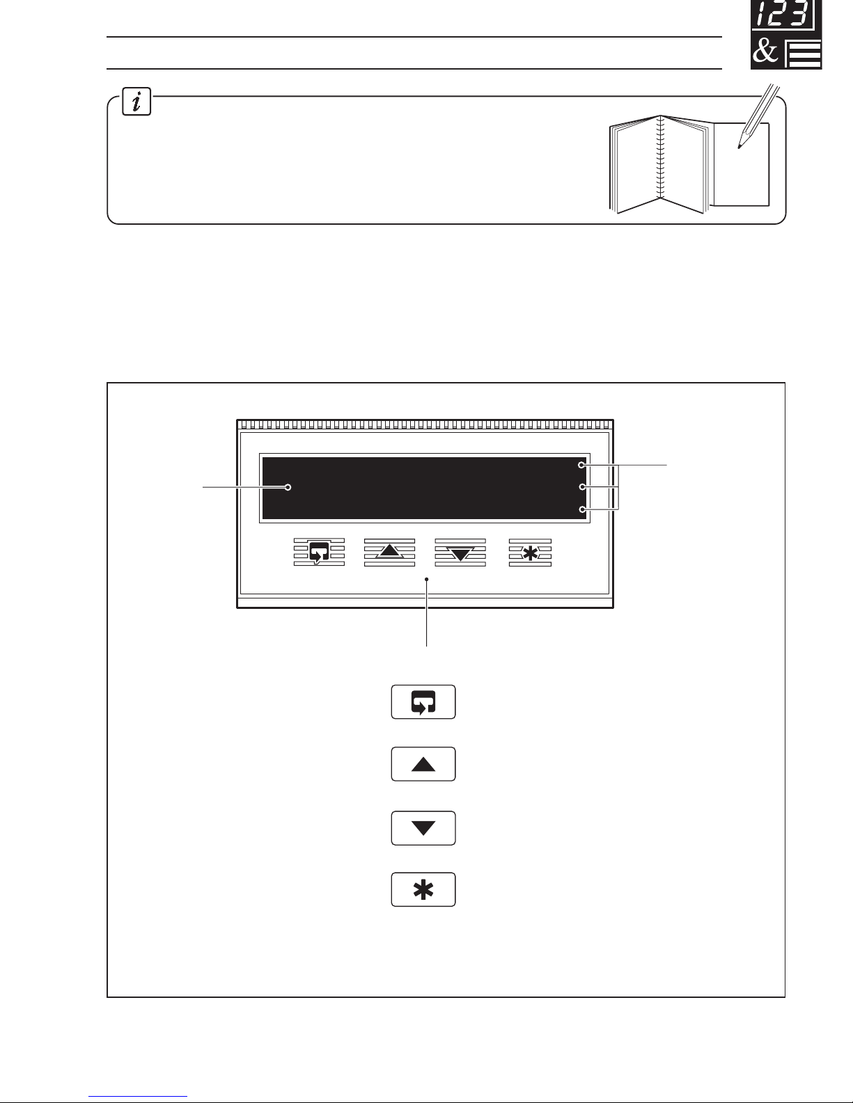
1 DISPLAYS AND FUNCTION KEYS .................................................................. 3
1.1 Introduction ............................................................................................... 3
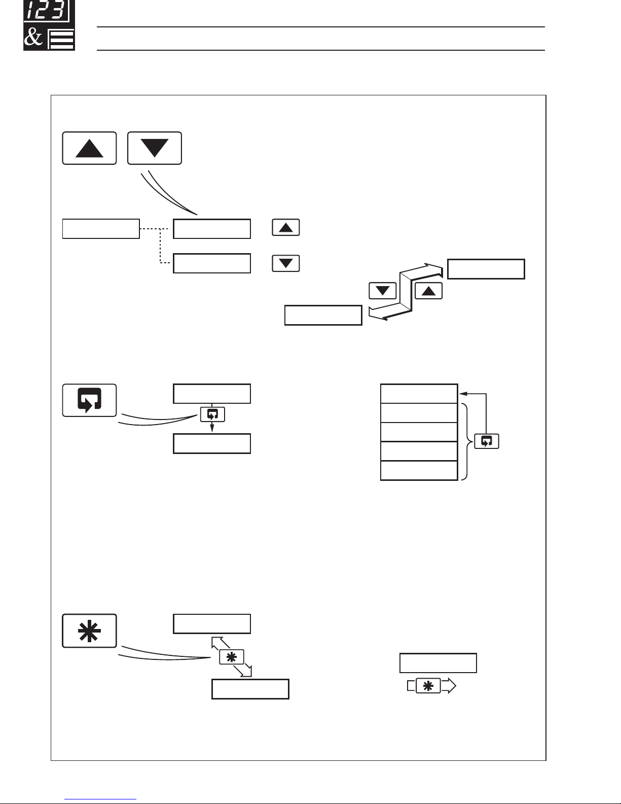
1.2 Use of Function Keys ................................................................................. 4
1.3 LED Alarms and Indicators ........................................................................ 5
1.4 Error Messages ......................................................................................... 6
2 OPERATOR MODE ........................................................................................... 7
2.1 Introduction ............................................................................................... 7
2.2 Operating Page – Standard (Level 1) ......................................................... 8
2.3 Operating Page – Totalizer (Level 1) .......................................................... 9
2.4 Operating Page – Maths Functions (Level 1) ........................................... 11
3 SET UP MODE ............................................................................................... 13
3.1 Introduction ............................................................................................. 13
3.2 Setup Level (Level 2) .............................................................................. 14
4 CONFIGURATION MODE ............................................................................... 18
4.1 Introduction ............................................................................................. 18
4.2 Accessing the Configuration Mode .......................................................... 18
4.3 Basic Hardware and Configuration (Level 3) ............................................ 20
4.3.1 Hardware Assignment and Input Type ........................................ 20
4.3.2 Alarms ....................................................................................... 22
4.3.3 Operator Functions and Totalizer Set Up .................................... 24
4.3.4 Digital Input and Serial Communications .................................... 26
4.4 Ranges and Passwords (Level 4) ............................................................ 28
5 INSTALLATION .............................................................................................. 31
5.1 Siting ....................................................................................................... 31
5.2 Mounting .................................................................................................. 33
5.3 Electrical Connections ............................................................................ 35
5.4 Relays, Arc Suppression, Inputs and Outputs ......................................... 35
5.4.1 Relay Contact Ratings ............................................................... 35
5.4.2 Arc Suppression ........................................................................ 35
5.4.3 Logic Output .............................................................................. 35
5.4.4 Retransmission Analog Output ................................................... 35
5.4.5 Digital Input ................................................................................ 35

3
888888
A1
A2
A3
Alarm LEDs
(secret-til-lit)
Display
Function Keys
Parameter Advance
Raise
Lower
Multi-function Key
1 DISPLAYS AND FUNCTION KEYS
Information.
The fold-out page inside on the back cover of this manual
shows all the frames in the programming levels. Space is
provided on the page for writing the programmed setting or
selection for each frame.
1.1 Introduction – Fig. 1.1
The COMMANDER 150 front panel display, function keys and LED indicators are
shown in Fig. 1.1.
Fig. 1.1 Front Panel Display, Function Keys and Indicators

4
A – Raise and Lower Keys
B – Parameter Advance Key
Frame 1
(top of level)
Frame 2
+
–
C – Multi-function Key
Use to change/set a parameter value…
Use to advance to the next
frame within a level…
or…
100.0 100.1
99.9
LEVEL1
100.1
CodE
0
Use to view a parameter setting or selection…
123456
…select individual characters in a frame
or…
…move between levels
LEVEL1
LEVEL2
LEVELx
100.1
200.2
300.3
400.4
Press and
hold
or…
…select the top (LEVEL) frame
from within a level
Note. This key also stores any changes made in the previous frame
…1 DISPLAYS AND FUNCTION KEYS
1.2 Use of Function Keys – Fig. 1.2
Fig. 1.2 Use of Function Keys

5
Alarm 1
COMMANDER 150
Alarm 2
Alarm 3
Alarm LEDs
A1
A2
A3
1 DISPLAYS AND FUNCTION KEYS…
1.3 LED Alarms and Indicators
LED Status
All Flashing
• Indicator is in the configuration mode – see Section 4.2.
A1, A2 and A3
• Flashes when Alarm is active (off when inactive).
• Lit constantly when Alarm 1 is an active latched alarm which has
been acknowledged
Fig. 1.3 LED Alarms and Indicators

6
9999
CAL.Err
CFG.Err
A.d. Err
DPt.Err
…1 DISPLAYS AND FUNCTION KEYS
Display Error/Action
Calibration error
Turn mains power off and on again
(if the error persists contact the
Service Organization).
Configuration error
The configuration and/or setup
data for the instrument is
corrupted. Turn mains power off
and on again (if error persists,
check configuration/setup settings).
A to D Converter Fault
The analog to digital converter is
not communicating correctly.
Process Variable Over/Under
Range
Option board error
Communications to the option
board have failed.
To Clear Display
Press the key
Press the key
Turn power on and
off again. If the error
persists, contact the
Service Organization
Restore valid
input
Contact the Service
Organization
1.4 Error Messages

7
2 OPERATOR MODE
2.1 Introduction
Operator Mode (Level 1) is the normal day-to-day mode of the COMMANDER 150.
Frames displayed in level 1 are determined by the indicator functions which are
selected during configuration of the instrument – see Section 4.
Note. Only the operating frames relevant to the configured functions are
displayed in Operator Mode.
The three indicator functions are:
• Standard Indicator – page 8
• Indicator with Totalization – page 9
• Indicator with Max./Min./Average – page 11

8
------
CodE
2145.3
UN-ACK
LEVEL1
•1
27.6
2145.3
…2 OPERATOR MODE
2.2 Operating Page – Standard (Level 1)
•1 Only displayed if there is an active latch alarm.
Process Variable
Normally displayed in engineering
units.
To view the process variable in
electrical units, press the key.
Global Alarm Acknowledge (latch alarms only)
UN-ACK. – alarm unacknowledged
ACK. – acknowledged
Security Code
Enter the correct code to access the setup level
(Level 2).
[0 to 9999]
Level 1
Note. To select to this frame from anywhere in
this level, press the key for a few seconds.

9
rSt-
2145.3
ACK-
123456
•1
•1
2 OPERATOR MODE…
2.3 Operating Page – Totalizer (Level 1)
These frames are only displayed if the totalizer function is enabled in the configuration
level – see Section 4.3.3
•1 Totalizer stop/go and reset from these frames can be disabled – see
Section 4.3.3.
A digital input can also be used to start/stop or reset the totalizer – see Section
4.3.4
Process Variable
To view the input value (in electrical units) press the
key.
Global Alarm Acknowledge (latch alarms only)
UN-ACK. – alarm unacknowledged
ACK. – acknowledged
Totalizer Value
When this frame is selected the current counter status
is displayed (t–GO or t-StOP).
Stop/Start
t–GO – start totalizer
t-StOP – stop totalizer
Reset
rSt-Y – reset totalizer
rSt- – do not reset totalizer
To reset the totalizer, select rSt-Y then press the
key.
Continued on next page.

10
999999
PrESEt
000000
PrEdEt
------
CodE
•1
•2
•1
Select Digit
Select Digit
LEVEL
…2 OPERATOR MODE
…2.3 Operating Page – Totalizer (Level 1)
•1 The predetermined value should be greater than the preset value when the
totalizer is counting up and lower than the preset value when the totalizer is
counting down.
•2 Only displayed if enabled in the configuration level – see Section 4.3.3.
Preset Total
This is the value the batch total is set to when it is reset
[000000 to 999999 flow units]
Predetermined Total
When the predetermined total is reached the batch
total is reset (with wrap on) or stops (wrap off),
depending on the wrap setting – see Section 3.2.
[000000 to 999999 flow units]
Security Code
Enter the correct code to access the setup level.
[0 to 9999]
Level 1
Note. To select to this frame from anywhere in
this page, press the key for a few seconds.

11
rSt-
2145.3
UN-ACK
A 140.5
H150.2
•1
2 OPERATOR MODE…
2.4 Operating Page – Maths Functions (Level 1)
Note. It is possible to have totalizer and maths functions together.
•1 This frame can be disabled – see Section 4.3.3.
The average value is reset automatically on power-up and can also be reset from
a digital input – see Section 4.3.4.
The reset function in this frame can be disabled – see Section 4.3.3.
Process Variable
To view the input value (in electrical units) press the
key.
Global Alarm Acknowledge (latch alarms only)
UN-ACK. – alarm unacknowledged
ACK. – acknowledged
Average Value
This is the mean average value of the process variable
input, since the average was reset.
rSt-Y – reset
rSt- – do not reset
To reset the average value, select rSt-Y then press
the key.
Continued on next page.

12
------
rSt-
H150.2
rSt-
L130.8
CodE
•1
•1
LEVEL1
…2 OPERATOR MODE
…2.4 Operating Page – Maths Functions (Level 1)
•1 This frame can be disabled – see Section 4.3.3.
The Max. and Min. values are reset automatically on power-up and can also be
reset from a digital input – see Section 4.3.4.
The reset reset function in this frame can be disabled – see Section 4.3.3.
Maximum Value
This is the maximum value of the process variable since
the maximum was reset.
rSt-Y – reset
rSt- – do not reset
To reset the maximum value, select rSt-Y then press
the key.
Minimum Value
This is the minimum value of the process variable since
the minimum was reset.
rSt-Y – reset
rSt- – do not reset
To reset the minimum value, select rSt-Y then press
the key.
Security Code
Enter the correct code to access the setup level.
[0 to 9999]
Level 1
Note. To select to this frame from anywhere in
this page, press the key for a few seconds.

13
8
LEVEL1
LEVEL2
A1xx
A2xx
A3xx
123456
t-GO
SEC.tot
PrESEt
PrEdEt
A xxxx
H xxxx
L xxxx
0AdJ
Level 2 – Set Up
Alarm 1 Trip Point
Alarm 2 Trip Point
Alarm 3 Trip Point
Batch Total
Totalizer Stop/Go
Secure Total/Reset
Preset Batch Total
Predetermined Batch
Total
Average Value
Maximum Value
Minimum Value
Offset Adjustment
Security
Code
Level 1 –
Operating Level
Correct
Password
CodE x
3 SET UP MODE
Fig. 3.1 Accessing the Setup Level (Level 2)
3.1 Introduction
To access the Setup Level (Level 2) the correct password must be entered in the
security code frame (CodE) in Level 1– see Fig. 3.1.

14
8
200.2
A1.hP
100.1
A2.LP
LEVEL2
•1
•1
A1. HYS
12.5
A2. HYS
27.9
A3.hP
•2
•2
…3 SET UP MODE
3.2 Setup Level (Level 2)
Level 2
Note. To select to this frame from anywhere in
this level, press the key for a few seconds.
Alarm 1 Trip Point
Alarm type:
A1.hP = High process alarm
A1.LP = Low process alarm
A1.HL = Latched high process alarm
A1.LL = Latched low process alarm
[In engineering units]
Alarm 1 Hysteresis Value
[In engineering units]
Alarm 2 Trip Point
Alarm type
[In engineering units]
Alarm 2 Hysteresis Value
[In engineering units]
Continued on next page.
•1 Not displayed if the alarm is disabled (No e selected) – see Section 4.3.2.
•2 Only displayed if custom alarm hysteresis is selected – see section 4.3.2

15
8
300.3
A3.hP •1
t-StOP
123456
rSt-
t-GO
SEC.tOt
•3
•3
•4
34.6
A3 HYS •2
3 SET UP MODE…
…3.2 Setup Level (Level 2)
•1 Not displayed if the alarm is disabled (No e selected) – see section 4.3.2
•2 Only displayed if custom alarm hysteresis is selected – see section 4.3.2
•3 Only displayed if enabled in the Configuration Level – see section 4.3.3
•4 A digital input can also be used to reset the batch total.
Alarm 3 Trip Point
Alarm type
[In engineering units]
Alarm 3 Hysteresis Value
[In engineering units]
Totalizer Value
rSt-Y – reset
rSt- – do not reset
To reset the maximum value, select rSt-Y then press
the key.
Totalizer Stop/Go
t-GO – start totalizer
t-StOP – stop totalizer
Setting to t-GO starts the totalizer counting towards
the predetermined value. Setting to t-StOP holds the
totalizer at its present value.
Continued on next page

16
8
PrESEt
000000
A140.5
PrEdEt
999999
•2
•2
456789
SEC.tOt
rSt-
•1
…3 SET UP MODE
…3.2 Set Up Level (Level 2)
•1 Only displayed if enabled in the Configuration Level – see Section 4.3.3.
•2 The preset value must be lower than the predetermined value when counting up,
and greater than the predetermined value when counting down.
Secure Total
The secure total is independent of the batch total value.
When 999999 or 000000 is reached, the total is reset
and then continues counting.
Total
Reset
rSt-Y – reset totalizer
rSt- – do not reset totalizer
To reset, select rSt-Y then press the key.
Preset Batch Total
This is the value the batch total is set to when it is reset.
[000000 to 999999]
Predetermined Batch Total
When this value is reached the batch total either resets
(with wrap on) or stops (wrap off) – see Section 4.3.3.
[000000 to 999999]
Continued on next page.

17
8
H150.2
rSt-
L130.8
rSt-
O.AdJ
1.0
•2
•2
A140.5
rSt-
•1
3 SET UP MODE…
…3.2 Set Up Level (Level 2)
•1 The average value is reset automatically on power-up and can also be reset from
a digital input – see Section 4.3.4.
•2 The maximum and minimum values are reset automatically on power-up and can
also be reset from a digital input – see Section 4.3.4.
Average Value
This is the mean average value of the process variable
input since the average was reset.
rSt-Y – reset
rSt- – do not reset
To reset, select rSt-Y then press the key.
Maximum Value
This is the maximum value of the process variable since
the maximum was reset.
rSt-Y – reset
rSt- – do not reset
To reset, select rSt-Y then press the key.
Minimum Value
This is the minimum value of the process variable since
the minimum was reset.
rSt-Y – reset
rSt- – do not reset
To reset , select rSt-Y then press the key.
Offset Adjustment
An offset can be applied to the process variable input to
enable spot calibration or the removal of system errors.
[±10% of engineering range]

18
Normal
Configure
4 CONFIGURATION MODE
Fig. 4.1 Accessing the Configuration Mode
4.1 Introduction
The Configuration Mode comprises two levels (3 and 4) as shown in Fig. 4.2.
Configuration level 3 is divided into four frames. For most simple applications it is only
necessary to set up the parameters in the first frame.
Note.
When in the configuration level:
• All the LED indicators flash.
• All relays and logic outputs are turned off.
• The analog output reverts to 0% (4mA) output level.
4.2 Accessing the Configuration Mode – Fig. 4.1
To access the Configuration Mode set the security switch to the 'Configure' position
(levels 1 and 2 cannot be accessed from this setting). When the configuration
parameters are programmed, reset the security switch to the 'Normal' position and
the Operating page is displayed automatically .
Table of contents
Other ABB Smoke Alarm manuals
Popular Smoke Alarm manuals by other brands

Mobeye
Mobeye CM2410 user manual

DSC
DSC AMS-220 Installation and operation instruction

Kidde
Kidde PI9000CA user manual

Halma
Halma Ampac Orbis IS ORB-OP-52027-APO Product guide

Ei Electronics
Ei Electronics EIB140RC Series instruction manual

System Sensor
System Sensor INNOVAIR DH100LP Installation and maintenance instructions

Secutron
Secutron MR-2602 installation manual

Fenwal
Fenwal PSD Series installation instructions

Greenheck
Greenheck Smoke Dampers SMD-401M Specifications

First Alert
First Alert SA500A Specification sheet

Honeywell
Honeywell FIre LIte ALarms D350PL Installation and maintenance instructions

Olympia
Olympia GS506 user manual