ABB FC650 Series Instruction manual

Security Products
Automatic Fire Detector in Conventional Technology
Detector Series FC650
Technical Data
Description
The FC650 fire detector series are conventional threshold
alarm detectors that comply with the respective standard of
the EN 54 standard series and are VdS approved.
The detectors feature an alarm indicator on the detector head
that is visible from all angles, and which can be triggered
with a permanent magnet for test purposes. A detector base
is provided for mounting and cable connection purposes,
into which the detector is simply plugged-in via the bayonet
connection. By connecting an address module to the
detector base, the relevant detector can be identified by the
alarm panel during an alarm, should the alarm panel have
the respective performance features. In this case, the first
detector that was triggered is detected for each detector
group.
Data can be read out of the detector and displayed using the
Programming Device FI700/PU. In this way, the degree of pol-
lution of the Optical Smoke Detector FC650/O can be read
out. The detector is screwed into the base of the FI700/PU for
this purpose, where the required data can be read out.
Application
The FC650 series offers detectors for different applications.
The Optical Smoke Detector FC650/O operates according
to the scattered-light principle and is used where smoke is
expected in case of a fire. The detector is equipped with
a dust barrier that protects the detector both against dust
contamination as well as penetration of outside light sources.
An insect screen prevents intrusion by small insects.
If factors such as dust, water vapour or cigarette smoke are
expected to affect the smoke detector operation or very fast
heat development is expected in the event of a fire, the Heat
Detectors FC650/TDIFF or FC650/TMAX should be used.
The Thermal Max. Detector FC650/TMAX triggers if a
predefined threshold temperature of 78 °C is exceeded.
The Thermal ROR Detector FC650/TDIFF also reacts to
fast increase in temperature, which generally occur in the
event of a fire, and at a temperature of 57 °C or higher.
The temperature is monitored with so-called measuring
thermistors.
All detectors are only intended for indoor use in dry ambience.
• Detector series compliant to EN 54 comprising
of smoke and heat detectors – VdS approved
• Alarm LED on the detector head
• Output of detector specic data using
the Programming Device FI700/PU
• Simple handling using bayonet connection
• Test activation possible using a magnet
• Anti-tamper mechanical block feature
• Remote indicator can be connected
to the detector base

-
-
+
RA
R
+
110 mm
72 mm
9 mm
110 mm
54 mm
Detector Detector + base
Application
Two types of detector bases are available for connection and
installation of the detectors. If the detectors are connected to
a fire control panel, the base FC600/BR is used. When con-
necting using 4-wire technology, for example, to an Intrusion
Alarm Panel or a KNX Zone Terminal, the relay base FC600/
BREL should be used (see separate data sheet).
The resistor that triggers the alarm is soldered into the detec-
tor base ex-works. The end of line resistor is connected to the
last base of a detector group in accordance with the connec-
tion schematic.
An LED on the detector head indicates the state of the detec-
tor. Optionally, a remote indicator (PA58-3) for remote signal-
ling of an alarm can be connected to the detector base (see
circuit diagram).
Electrical connection - circuit example with 3 detectors
Unlatching the detector I Dimensional drawing
Automatic Fire Detector in Threshold Alarm Technology
Should there be a requirement to hinder easy removal of the
detector from the base, a small plastic peg on the side of the
detector base can be broken off by inserting a solid object
through the aperture on the detector base. Only after insertion
at the same point, for example, of a screwdriver, is it possible
to unlatch the detector and turn it out of the base
(see “Unlatching the detector” illustration below).
Engineering
The number of detectors and the installation locations result
from the engineering specifications for fire detectors
VDE 0833 – part 2 and the engineering guidelines compliant
to VdS 2095, should there be any insurance related
requirements.
RA
-
Knock out
-
-
+RA
R
+
BM
Detector
circuit
-
-
+RA
R
+
-
-
+RA
R
+
+
Parallel display
(can be used on each
detector if required)
Detector circuit termination
resistor in the last detector – 5.6 k
Ω
Address module
(can be used on each
detector if required)
If a series resistor is not integrated
before the LED in the detector parallel display,
a 1 kΩresistor must be used at this point!
+
-
Note:
Address module and parallel display are only displayed for the purpose of example and are not absolutely necessary!
NG58/1

Automatic Fire Detector in Threshold Alarm Technology
Installation
The detector bases are fixed on the ceiling with 2 screws,
after the corresponding preparations have been made.
The detector is mounted horizontally as standard.
The location of the mounting bores can be found in the
“Dimensional drawing” section.
During installation, it is important to ensure that the base does
not warp when installed on an uneven ceiling, as it may make
it difficult or impossible to plug-in the detector. The detector
is placed against the base and screwed onto the base in a
clockwise direction.
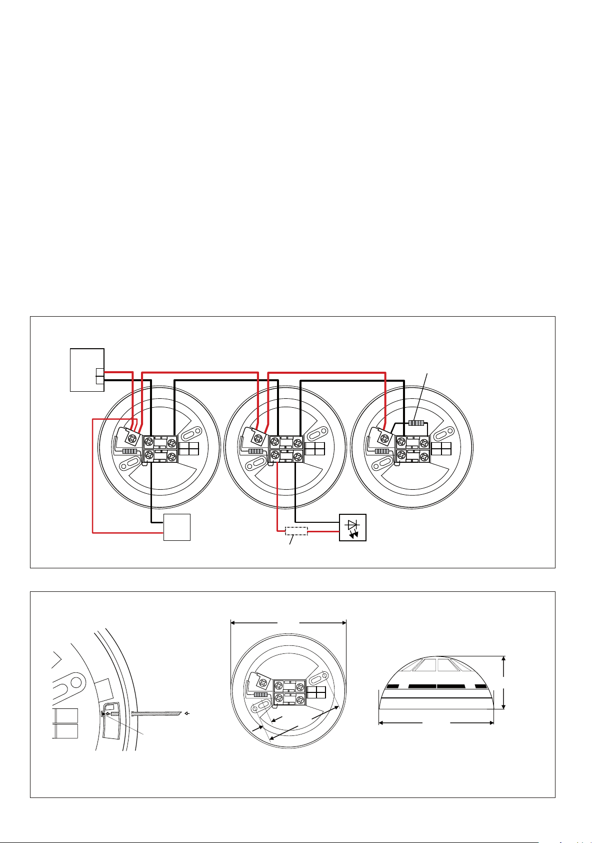
Cable connection
With flush-mounted cabling, it is necessary to ensure that all
the required conductors for standard wiring are located on the
“R+” terminal side. The incoming and outgoing conductors
can be inserted through the same aperture on the socket
base (also see the dimensional drawing).
With flush-mounted cabling, it is also advantageous if
both cables are inserted on the side of the base, where
the terminal “R+” and the terminals for all other standard
applications are located.
When introducing the cable from 2 sides, the location of the
base should be selected, so that the breaking points for the
cable entry on the base are offset longitudinally to the cable
path by 180 °. The individual wires can be fed both within the
base interior as well as from underneath the base, from one
half of the base to the other. Cables up to 2 x 2 x 0.8 mm
can be inserted to the base together with the sheath; thicker
cables will require removal of the sheath outside the base.
If the cable shield (sheath wire) of incoming and outgoing
cables is to be looped through, this must be implemented in
the base, e.g. using a ferrule or similar device.
Test activation
A test activation can be undertaken by holding a permanent
magnet at the smoke inlet aperture level (these are also
available on the heat detectors) located at about 100° in a
counter-clockwise orientation starting from the rectangular
opening on the side of the detector base on the detector.
Inspection/Maintenance
Every detector must be physically activated at least once a
year to test its function in accordance with VDE 0833 part 1.
A suitable testing aerosol is recommended for activation of
smoke detectors; heat detectors should be activated using a
heat gun or a hair drier.
Technical Data
Electrical values
Operating voltage 10 to 30 V DC
Quiescent current
consumption
FC650/O
FC650/TMAX-TDIFF
Typ. 90 µA, at typ. 24 V DC line voltage
and 25 °C
Typ. 90 µA, at typ. 24 V DC line voltage
and 25 °C
Alarm current Max. 40 mA, limited by alarm resistor
in detector base (do not short-circuit)
General data
Temperature range -30 °C to +70 °C
Application temperature
Max. 45 °C (FC650/TDIFF)
Max. 60 °C (FC650/TMAX)
Activation temperature
57 °C (FC650/TDIFF)
78 °C (FC650/TMAX)
Air humidity Max. 95 % relative (without condensation)
Enclosure IP30
Manufacturing date Label on detector base
Dimensions W x H
Detector
Base
Detector + Base
106 mm x 46 mm
110 mm x 16 mm
110 mm x 54 mm
Weight Approx. 80 g
Colour White
Material Plastic
Approvals
FC650/O
FC650/TMAX
FC650/TDIFF
VdS No. G 210145
VdS No. G 210151
VdS No. G 210151
Applicable standard
FC650/O
FC650/TMAX
FC650/TDIFF
EN 54-7
EN 54-5 – class B
EN 54-5 – class A1R
Specifications according to Building Products Act
0832
10
0832-CPD-1417 FC650/O
0832-CPD-1418 FC650/TMAX
0832-CPD-1418 FC650/TDIFF
EN54-7:2000 + A1:2002
Smoke detectors - Point detectors using
scattered light
EN54-5:2000 + A1:2002
Heat detectors - Point detectors
Side aperture
on detector base
About 100 °
Hold at
aperture height

Order Number 2CDC 542 040 D0203 printed in Germany (07/12-2-ZVD)
Ordering Information
Product photo Description Short
designation
Order code bbn
40 16779
EAN
Price
group
Weight
1 pcs
kg
Pack
unit
Quantity
Optical Smoke Detector
VdS No. G210145
FC650/O 2CDG 430 079 R0011 86479 4 P6 0.07 1
Static Heat Detector
VdS No. G 210151
FC650/TMAX 2CDG 430 081 R0011 86477 0 P6 0.07 1
Thermal ROR Detector
VdS No. G 210151
FC650/TDIFF 2CDG 430 080 R0011 86478 7 P6 0.07 1
Universal Detector Base
for Series FC650
FC600/BR 2CDG 430 050 R0011 70839 5 P6 0.04 1
Detector Base 12/24 V
for Series FC650
FC600/BREL 2CDG 430 051 R0011 70840 1 P6 0.06 1
Test Aerosol for Smoke
Detector Testing
FPA03 GH V902 0012 V0021 53444 4 P6 0.3 1
Programming device for reading
data on the FI700 and FC650
detector series
FI700/PU 2CDG 430 064 R0011 69824 5 P6 0.2 1
Automatic Fire Detector in Threshold Alarm Technology
Note:
We reserve the right to make technical changes or
modify the contents of this document without prior
notice. With regard to purchase orders, the agreed
particulars shall prevail.
ABB AG does not accept any responsibility
whatsoever for potential errors or possible lack of
information in this document.
We reserve all rights in this document and in the
subject matter and illustrations contained
therein. Any reproduction, disclosure to third parties
or utilization of its contents - in whole
or in parts - is forbidden without prior written
consent of ABB AG.
Copyright© 2012 ABB
All rights reserved
ABB STOTZ-KONTAKT GmbH
Eppelheimer Straße 82
69123 Heidelberg, Germany
Phone: +49 (0)6221 701 607
Fax: +49 (0)6221 701 724
E-Mail: [email protected]
Further Information and Local Contacts:
www.abb.com/knx
Data output with FI700/PU
Using the FI700/PU, certain data and values can be read from
the detector after the respective detector has been screwed
into the base of the FI700/PU. For this purpose, the corre-
sponding detector series must be selected in the first step on
the FI700/PU. Then the data can be read. More details can be
found on the data sheet of the FI700/PU.
Displayed data in dependence on the device type
Function/Device FC650/O FC650/TMAX FC650/TDIFF
Type FC650/O FC650/T FC650/T
Quiescent value x
Pollution in % x
Type of heat sensor x x
Firmware xxx
Manufacturing date xxx
Factory test date xxx
LED function
Battery state in % xxx
This manual suits for next models
6
Other ABB Smoke Alarm manuals