GE ESL 570N User manual

1
ESL 572NS Smoke Detector
4300 Series
Wireless Smoke Alarm
ESL 570N Smoke Detector
Model:572NS
Installation Instructions
OEM
Accounts
Only
CSFM
Description
The ESL 572NS smoke detector must be used as part of a
wireless system and requires a transmitter.
The detector provides the following features:
CleanMe Self-diagnosticsmonitors its own sensitivity and
operational status. If the detector drifts out of the UL listed
sensitivity range or fails internal diagnostics, it extinguishes
its LED and sends a trouble signal to the control panel.
Tamper switch sends a trouble signal to the control panel
when the detector is removed from its mounting base.
Transmitted Signal Outputs
Once a wireless transmitter is installed, the detector can
transmit the following signals to the control panel:
• Alarm • CleanMe
• Alarm restore • Maintenance alert
• Low battery • Tamper
Since regulations pertaining to smoke detector installation vary
from state to state, contact the authority having jurisdiction
(AHJ). Where public safety is primary, theAHJ may be a
federal, state, local, or other regional department or individual
such as a fire chief, fire marshal, chief of a fire prevention
bureau, labor or health department, building official, electrical
inspector, or others having statutory authority. For insurance
purposes, an insurance inspection department, rating bureau,
or other insurance company representative may be the AHJ. In
some cases, the property owner or their designated agent
assumes the role of the AHJ. At government installations, the
commanding officer or department official may be theAHJ.
General Guidelines
•Locate the detector in evironmentally controlled areas
where the temperature range is between 40° and 100° F
(4.4° and 37.8° C) and the humidity is between 0 and 90%
noncondensing.
•Locate detectors away from ventilation sources that can
prevent smoke from reaching the detector.
•Locate ceiling mounted detectors in the center of the room
or hallway, at least 4 inches (10cm) away from any walls or
partitions.
•Locate wall mounted detectors so the top of the detector
is 4 to 12 inches (10 to 31cm) below the ceiling.
•In rooms with sloped, peaked, or gabled ceilings, locate
detectors 3 feet (.9 meters) down or away from the highest
point of the ceiling.
•When mounting to suspended ceiling tile, the tile must be
secured with the appropriate fastener to prevent tile
removal.
Installation Guidelines
Selecting a suitable location is critical to the operation of
smoke detectors. This equipment should be installed in
accordance with the National Fire ProtectionAssociation’s
(NFPA) Standard 72, Chapters 2 and 8. Depending on the
application, you may need to reference other chapters of
NFPA72orNFPA101.
Figure 1 - Detector Features
Optional
temperature
sensor
LED
Soundervent
Optional
temperature
sensor
Test
button

2ESL 572NS Smoke Detector
Installing the Detector
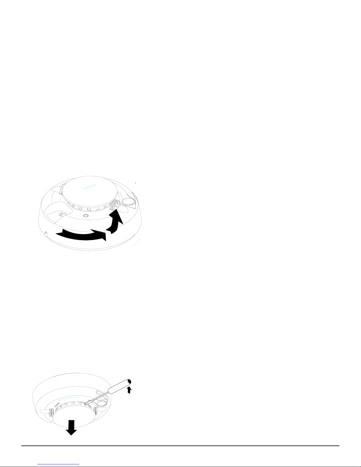
1. Slide the battery compartment cover away from the detector
to unsnap it and lift it off. See Figure 3.
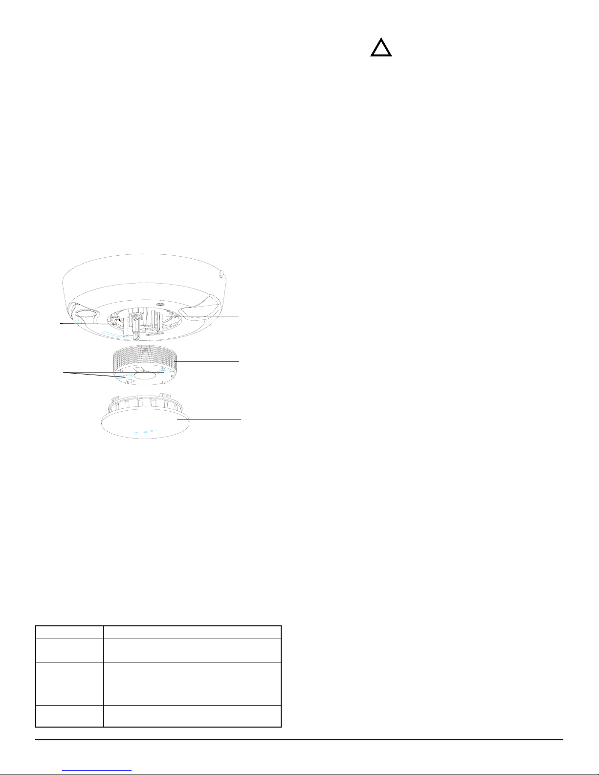
2. Observing proper polarity, insert two 3Vlithium batteries into
the detector battery compartment and replace the battery
compartment cover.
3. Locate and record the seven digit ID address from the
transmitter and program it into the RF gateway receiver and
control panel. See the control panel programming guide.
4. Remove the red plastic dust cover from the detector. The
detector is shipped with a dust cover for protection on
construction sites with dusty environments.
5. Ifapplicable, disconnect the alarm notification appliances,
service release devices and extinguishing systems and test the
NFPA Guidelines
NFPA 72, 2-1.4.2.1 Total (Complete) Coverage. If required,
total coverage shall include all rooms, halls, storage areas,
basements, attics, lofts, spaces above suspended ceilings, and
other subdivisions and accessible spaces; and the inside of all
closets, elevator shafts, enclosed stairways, dumbwaiter
shafts, and chutes. Inaccessible areas shall not be required to
be protected by detectors. (For exceptions, refer to this section
ofNFPA72.)
NFPA 72, 2-1.4.2.2 Partial Coverage. If required, partial
detection systems shall be provided in all common areas and
work spaces, such as corridors, lobbies, storage rooms,
equipment rooms, and other tenantless spaces in those
environments suitable for proper detector operation in accor-
dance with this code.
NFPA 72, 2-1.4.2.3 Selective Coverage. Where codes,
standards, laws, or authorities having jurisdiction require the
protection of selected areas only, the specified areas shall be
protected in accordance with this code.
NFPA 72, 2-1.4.2.4 Supplementary (Non required) Coverage.
Where installed, detection that is not required by an applicable
law, code, or standard, whether total (complete), partial, or
selective coverage, shall conform to the requirements of this
code. (For exceptions, refer to NFPA72 Chapter 2 Spacing
Requirements.)
NFPA 72, 2-1.4.3 Where non required detection devices are
installed for a specific hazard, additional non required
Locations toAvoid
Do not install smoke alarms/detectors:
•in or near areas where combustion particles are normally
present such as in kitchens, garages, near furnaces, hot
water heaters, or gas space heaters.
•on the ceiling in rooms next to kitchens where there is no
transom between the kitchen and such rooms.
•in damp or very humid areas or next to bathrooms with
showers. Locate detectors at least 5 feet (1.5 meters) away
from bathrooms.
•in very cold or very hot areas.
•in dusty, dirty, or insect infested areas.
•near fresh air inlets or returns or excessively drafty areas.
Heating/air conditioning vents, fans, and fresh air intakes
can drive smoke away from smoke alarms/detectors.
•in dead air spaces at the top of peaked ceilings or in
corners where walls and ceiling meet. Dead air may
prevent smoke from reaching a smoke alarm/detector.
•near fluorescent light fixtures. Locate smoke alarms/
detectors at least 10 feet (3 meters) away from these
fixtures.
H a l l
O f f i c e O f f i c e
C o n f e r e n c e R o o m
C l o s e t
E l e v a t o r
M e n s L a d i e s
O f f i c e
O f f i c e
O f f i c e
S t a i r w e l l
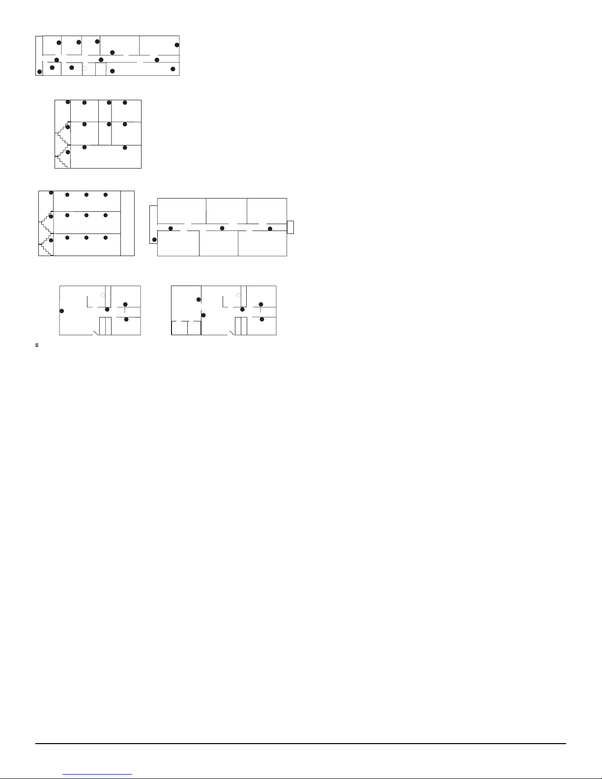
I n c o m m e r c i a l b u i l d i n g s a s m o k e d e t e c t o r
s h o u l d b e l o c a t e d i n e a c h r o o m .
H
A s m o k e d e t e c t o r
s h o u l d b e l o c a t e d
o n e a c h l e v e l .
O f f i c e O f f i c e
L o b b y
H a l l
O f f i c e O f f i c e
S t a i r w e l l
H a l l
detection devices shall not be required to be installed
throughout an entire room or building.
NFPA 72, 2-2 Heat-Sensing Fire Detectors Heat-sensing fire
detectors shall be installed in all areas where required by the
NFPA codes and standards or by the authority having
jurisdiction.
NFPA 72, 8-1.4.1.3.2 Detection in New Apartment Buildings
Approved, single-station smoke alarms shall be installed in
accordance with 7-6.2.10 of NFPA101 outside every sleeping
area in the immediate vicinity of the bedrooms and on all
levels of the dwelling unit including basements. (101: 18-
3.4.4.2) (For exceptions, refer to this section of NFPA72.)
NFPA 72, 8-1.4.1.4.2 Detection in Existing Apartment
Buildings Approved, single-station smoke alarms shall be
installed in accordance with 7-6.2.10 of NFPA101 outside
every sleeping area in the immediate vicinity of the bedrooms
and on all levels of the dwelling unit including basements.
(101: 19-3.4.4.1) (For exceptions, refer to this section of NFPA
72.)
Figure 2 - Smoke Detector Placement
I n m u l t i f a m i l y d w e l l i n g s , s m o k e a l a r m s / d e t e c t o r s s h o u l d
b e l o c a t e d i n h a l l w a y s a n d s t a i r w e l l s o f e a c h l e v e l .
F i r s t F l o o r
S t a i r w e l l
S e c o n d F l o o r
T h i r d F l o o r
H a l l
A p a r t m e n t
S t a i r w e l l
E l e v a t o r
A p a r t m e n t
A p a r t m e n t A p a r t m e n t
A p a r t m e n t
A p a r t m e n t
S
m o k e a l a r m s / d e t e c t o r s s h o u l d b e l o c a t e d i n t h e l i v i n
g
a r e a , h a l l w a
y
, a n d i n e a c h b e d r o o m o f t h e a p a r t m e n t .
L i v i n
R o o m
B e d r o o m
B e d r o o m
D i n i n
R o o m K i t c h e n
H
B a t h r o o m
C l o s e t
C l o s e t
C l o s e t
B e d r o o m
B e d r o o m
K i t c h e n
H
B a t h r o o m
C l o s e t
C l o s e t
C l o s e t
D i n i n
A r e a
L i v i n
R o o m
B e d r o o m
B a t h r o o m
C l o s e t
E l e v a t o r

3
ESL 572NS Smoke Detector
communication between the control panel and the detector
before permanently mounting the detector as follows:
-Hold the detector up where you plan to install it.
-Press the Test button on the detector for 4 seconds. The
detector sends a signal to the control panel.
- At the control panel, verify the signal was received and the
RF signal strength is adequate. If no signal is received or the
RF signal is low, relocate the detector and retest.
6. Using the two screws and anchors provided, mount the base.
7. Attach the detector to the mounting base as follows:
-Line up the raised alignment tab on the lip of the detector
with the arrow on the mounting base. See Figure 4.
-Insert the smoke detector into the base and turn clockwise
approximately 15 degrees. It should snap firmly into place.
Important: The detector cannot be attached to the mounting
base if no batteries are installed.
8. Test the communication between the control panel and
detector as follows:
- Press the Test button on the alarm for 4 seconds. The
detector sends a signal to the control panel.
-At the control panel, verify that the signal was received.
9. Test the detector (see Smoke Testing the Detector) and if
applicable, reconnect the alarm notification appliances, service
release devices and extinguishing systems.
Important: The control panel alarm and all auxiliary functions
should be verified for a complete test of the system.
Smoke Testing the Detector
Smoke detectors should be tested in place annually using one of
the following methods:
A. Use Smoke! in a can® (product number SM-200), a canned
aerosol simulated smoke and follow the directions on the can.
B. Use the following steps to test the detector with smoke:
1. Hold a smoldering punk or cotton wick close to the smoke
entry openings.
2. Gently direct the smoke into the detector for 20 seconds or
until an alarm is indicated.
Be sure to extinguish the smoke source after testing! The
detector LED should stay on and an alarm should be indicated at
the control panel. Use the system reset switch to reset the
detector.
Figure 3 - Battery Compartment
Battery
compartment
Figure 4 - Smoke Detector-to-Base Alignment
Testing the Detector Sensitivity
The detector provides a sensitivity level test mode that allows
you to check the detector sensitivity using the Test button
and the LED indicator on the detector as follows:
1. Press the Test button on the detector for 4 seconds. Once
the test starts, the detector LED flashes one to nine times.
2. Count the number of times the LED flashes and use the
following table to determine the status of the detector
sensitivity and what action to take, if any.
Flashes Indication Action
1 Unserviceable Reset unit and rerun sensitivity test.
hardware fault If error persists, replace the unit.
2-3 Detector is Clean the unit. Reset the unit and
becoming rerun sensitivity test. If the error
insensitive. persists, replace the unit.
4-7 Detector is N/A
within normal
sensitivity
range.
8-9 Detector is Verify that the smoke chamber is
becoming too snapped down securely. Clean the
sensitive. unit and replace the smoke chamber.
Afterthe flashes, if the sensitivity is within limits and all
othertestspass,thedetectorgoesinto alarm and resets after
7 seconds.
If the sensitivity is not within limits, or an unserviceable
hardware fault has been detected, the detector LED extin-
guishes until the detector is serviced and the built-in transmit-
ter sends a CleanMeor maintenance alert signal to the
control panel.
Alignment tab
Alignment arrow

4ESL 572NS Smoke Detector
When to Replace the Batteries
The smoke detector requires two 3V lithium 123 batteries as listed
on the battery compartment cover. The required batteries are
available where other batteries are sold.
Battery life is a minimum of 1 year and varies depending on how
often the alarm is tested. When the batteries are low, the detector
sends a low battery signal to the control panel, extinguishes its
LED, and chirps every 45 seconds until the batteries are replaced.
The low battery trouble chirps can be silenced for 24 hours by
pushing the Test button.
Replacing the Batteries
Use only 3V lithium 123 batteries as listed on the battery com-
partment cover.
1. Remove the detector from the mounting base. See Attaching
and Removing the Detector.
2. Slide the battery compartment cover away from the detector to
unsnap it and lift it off. See Figure 3.
3. Remove the batteries and dispose of them properly.
4. Observing correct polarity, insert two new 3V lithium batteries
into the battery compartment and replace the cover. Use only
new batteries when replacing the old batteries.
5. Reattach the detector to the mounting base. See Attaching and
Removing the Detector.
6. Test the system.
Cleaning the Detector
Clean the detector cover with a dry or damp (water) cloth as
needed to keep it free from dust and dirt.
When necessary, clean the detector interior and replace the
smoke chamber as follows:
1. Disconnect the alarm notification appliances, service release
devices, and extinguishing systems.
2. Remove the detector from its mounting base. See Attaching
and Removing the Detector.
3 Remove the batteries. See Replacing the Batteries.
4. Slide a flat-blade screwdriver in the slot on the detector cap
and gently push the handle down to pry the cap up and off.
SeeFigure 5.
5. Squeeze the smoke chamber where indicated by the alignment
arrows and pull it up and away from the detector and discard.
SeeFigure 6.
6. Blow out or use a soft-bristled brush to remove dust and dirt
from the smoke chamber base.
7. Line the new smoke chamber up with the optical base by
lining up the arrows on the smoke chamber to the latches on
the optical base and snap down into place.
8. Replace the detector cap as follows:
-Line the cap up with the smoke detector.
Attaching and Removing the Detector
Toremovethe detectorfromthemounting base,grasp the
detector and turn it counterclockwise approximately 15
degrees. The detector should snap off of the mounting base.
Attachthe smokedetector toitsmounting baseasfollows:
- Line up the raised alignment tab on the lip of the smoke
detector with arrow on the mounting base. See Figure 3.
- Insert the smoke detector into the base and turn
clockwise approximately 15 degrees. It should snap
firmlyinto place.
Understanding the Test Button
The Test button on the detector performs three functions as
follows:
Testing = Press the Test button for 4 seconds. The detector
performs a sensitivity test and then sends a test signal to the
control panel.
Silence alarm = Press to silence the sounder during an alarm.
After a few minutes, the sounder and alarm resume if smoke is
still present.
Silence trouble chirp = Press to silence a trouble chirp. The
trouble chirp resumes after 24 hours if the trouble condition is
not corrected.
Understanding the LED
The LED on the detector indicates the status of the detector
as follows:
FLASHING = Flashes every 8 seconds to indicate normal
operation.
ON = Detects smoke, sending an alarm.
OFF = Trouble or maintenance is required. Check the control
panel to determine what action to take.
Figure 4 - Removing the detector from the base
Figure 5 - Removing Detector Cap

5
ESL 572NS Smoke Detector
Maintaining the Detector
The smoke detectors are designed for easy field service and
maintenance. When installed and used properly, they require
minimalmaintenance.
The smoke detector should be tested weekly. See Testing the
Detector Sensitivity and Smoke Testing the Detector.
When the detector requires maintenance, it extinguishes its
LED and sends a signal to the control panel as described in the
followingtable.
Signal Maintenance required
CleanMe Smoke detector sensitivity is out of range and
needs cleaning. See Cleaning the Detector.
Maintenance alert Detector failed power up self test. Perform a
sensitivity test. See Testing the Detector
Sensitivity. If the problem persists, replace the
detector.
Low battery Batteries in the detector are low, replace the
batteries.
WARNING
SmokedetectorsCANNOTprovidewarningsfor
firesresultingfromexplosions, smoking in bed or
otherfurniture, ignitionofflammable liquids,
vaporsand gases,childrenplaying withmatchesor
lighters.
!
Limited Warranty
ESL is a brand name of GE Interlogix. The manufacturer warrants this
smoke detector (except batteries) to be free from defects in material
and workmanship under conditions of normal use for a term of 3 years
from the date of manufacture.
During the warranty period, if a GE Interlogix product or any of its
components becomes defective, it will be repaired or replaced
without charge.
Out-of-warranty units will be repaired at the discretion of the
manufacturer, if not, a card will be forwarded to the customer
suggesting a replacement unit and the cost of that unit.
This warranty does not apply to units which have been subject to
abuse, misuse, negligence or accident, or to which any modifications,
alterations or repairs have been made or attempted.
This warranty is extended only to the original purchaser of the smoke
detector and may be enforced only by such person. During the
warranty period, if the detector or any warranted components thereof
becomes defective, at the manufacturer’s discretion, it will be replaced
or repaired without charge if returned in accordance with the following
instructions:
Obtain a Return Authorization Number by calling 1-800-648-7422 or
503-692-4052, then carefully pack the detector in a well padded and
insulated carton and return, postal charges prepaid to:
Customer Service RMA#
GE Interlogix
12345 SW Leveton Drive
Tualatin, OR 97062-9938
A note should be included advising the nature of the malfunction.
Care must be exercised in the proper packing of detectors returned
under this warranty as GE Interlogix will not be responsible for
warranty repairs to equipment damaged because of improper packing.
The above warranty is in lieu of all other express warranties, and
implied warranties of merchantability and fitness for a particular
purpose are limited in duration for a period of 3 years from the date
of manufacture. Under no circumstances shall manufacturer be
liable to the purchaser or any other person for incidental or
consequential damages of any nature, including without limitation
damages for personal injury or damages to property, and however
occasioned, whether alleged as resulting from breach of warranty
by manufacturer, the negligence of manufacturer or otherwise.
Manufacturer’s liability will in no event exceed the purchase price
of the product. Some states do not allow limitations on how long an
implied warranty lasts, or the exclusion or limitation of incidental
or consequential damages, so the above limitations and exclusions
may not apply to you. Unless a longer period is required by
applicable law, any action against manufacturer in connection with
this smoke detector must be commenced within one year after the
cause of action has occurred.
No agent, employee, or representative of the Manufacturer nor any
other person is authorized to modify this warranty in any respect.
Repair or replacement as stated above is the exclusive remedy of the
purchase hereunder. This warranty gives you specific legal rights and
you also have other rights which vary from state to state.
-Insert the cap into the smoke detector and turn
clockwise approximately 15 degrees. It should
snap firmly into place.
9. Observing the proper polarity, put the batteries back in the
detector and replace the battery compartment cover.
10.Reattach the detector to its mounting base. See Attaching
and Removing the Detector.
11.Test the detector sensitivity (see Testing the Detector
Sensitivity) and reconnect all detector notification
appliances, service release devices and extinguish-
ing systems.
Important: The control panel alarm and all auxiliary functions
should be verified for a complete test of the system.
Smoke
chamber
latch
Detector
cap
Opticalbase
Smoke
chamber
Figure 6 - Detector Parts
Alignment
arrows

6ESL 572NS Smoke Detector
Specifications
Voltage......................................................................................3VDC
Typical average standby current ......................................... 35µA
Typicaltest current.................................................................. 2mA
Typicalalarm current............................................................ 70mA
Batterylife......................................................................1 year (min)
Batterytype .........................................3Vlithium, Duracell123;
..................................Sanyo, PanasonicCR123A
Low battery threshold......................... low battery signal at 2.7V
Sounder.......................................... 85dBa at 10' temporal pattern
Low battery beep rate ..............................1 every 45 sec. ± 2 sec.
Sensitivity............................................................. 2.25% ±1.35 %
Operatingtemperature ................................40°-100°F(4.4°-37.8°C)
Operating humidity range ...................... 0-95% non-condensing
Color........................................................................................White
Detectordimensions .........................5.6"x 2.4"(14.3cm x 6.1cm)
Basedimensions ............................5.4"x 0.46" (13.7cm x 1.17cm)
Driftcompensation adjustment ............................... 0.5%/ft. max.
Listings..............................................................UL268, CSFM,CE
Limitations
Smoke detectors may not work under all conditions. Smoke
detectors cannot provide total protection of life or property and are
not a substitute for insurance. All alarms are subject to possible
compromise or failure-to-warn for a variety of reasons. For example:
•This smoke detector will not operate and an alarm will not
sound if its batteries are dead, removed, or not installed
correctly.
•Radio signals transmitted by this smoke detector may be
blocked or reflected by metal objects.Adjacent devices or
systems using radio frequency signals may interfere with the
operation of this detector. Test the system weekly to ensure
signals are transmitted and received properly.
•Closed or partially closed doors and distance can block or
reduce the alarm sound from this detector. This detector is not
designed for the hearing impaired.
•Smoke detectors cannot detect smoke inside chimneys, walls,
roofs, or smoke blocked by a closed door.
•Smoke detectors may not detect smoke on other levels of the
building.
•Smoke detectors may not warn in time when fires are caused by
smoking in bed, explosions, improper storage of flammables,
overloaded electrical circuits, or other hazardous conditions. FCC Compliance
This device complies with Part 15 of the FCC rules. Operation is
subject to the following two conditions: (1) this device may not
cause harmful interference, and (2) this device must accept any
interference received, including interference that may cause
undesired operation.
Model Description
572NS 3V wireless transmitter-compatible smoke detector, two 3V lithium batteries, 85dBa sounder, base tamper
Accessories
SM-200 Smoke! in a can® (canned smoke) for functional testing of smoke detectors
SM-EXT1 Extension tube for Smoke! in a can®
211 Replacementsmoke chambers(set of10)
60-933 6 pack 3V lithium batteries
Product Ordering
Means of Conformity
We declare under our sole responsibility that this product is in
conformity with Directive 93/68/EEC (Marking) and directive 89/
336/EEC (EMC) based on test results using (non)-harmonized
standards in accordance with the Directives mentioned.
1039260-Rev B 04/03
www.GE-Interlogix.com
© 2003GE Interlogix
12345 SW Leveton Drive
Tualatin, OR 97062
Phone:503-692-4052
USA & Canada: 800-547-2556
Technical Service: 800-648-7424
FaxBack:800-483-2495
GE Interlogi
x
This manual suits for next models
2
Table of contents
Other GE Smoke Alarm manuals

GE
GE 429CT User manual

GE
GE ESL 560N Series User manual

GE
GE ADTGC-HDVM Assembly instructions

GE
GE 782136710441 User manual

GE
GE TX-6212-03-1 Assembly instructions

GE
GE 60-992-900 User manual

GE
GE TX-6010-01-1 User manual

GE
GE FHSD720C User manual

GE
GE ESL 700 Series User manual

GE
GE Z630-3 Assembly instructions
Popular Smoke Alarm manuals by other brands

Convoy Security
Convoy Security YT202 Installation and maintenance instructions

HST
HST HD203B Installation and maintenance instructions

Edwards
Edwards SIGA-270 manual

Xtralis
Xtralis ICAM IAS-1 Product guide

Bosch
Bosch Bosch Appliances Smoke Alarm FLM325IM Modular device

Finsecur
Finsecur CAP 212 Installation and operation manual