4CURRENT AND VOLTAGE INSTRUMENT TRANSFORMERS
INSTRUCTIONS FOR INSTALLATION, USE AND MAINTENANCE
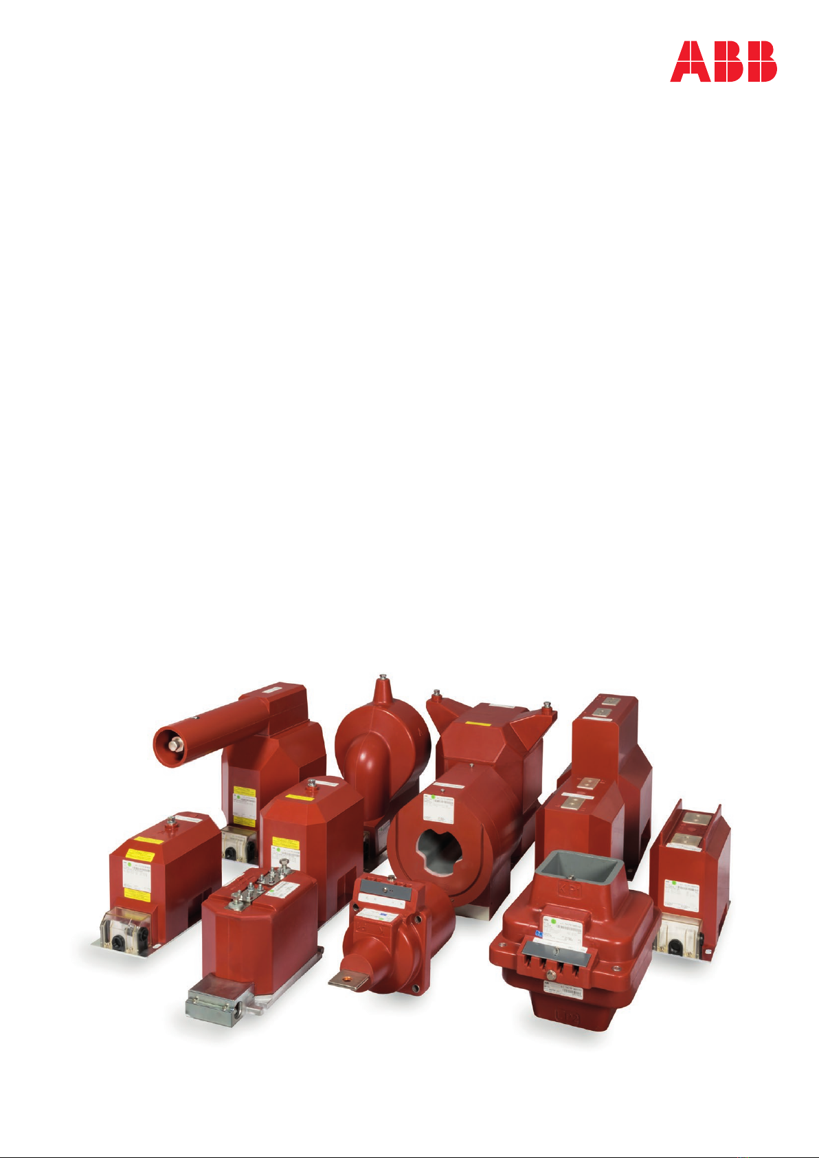
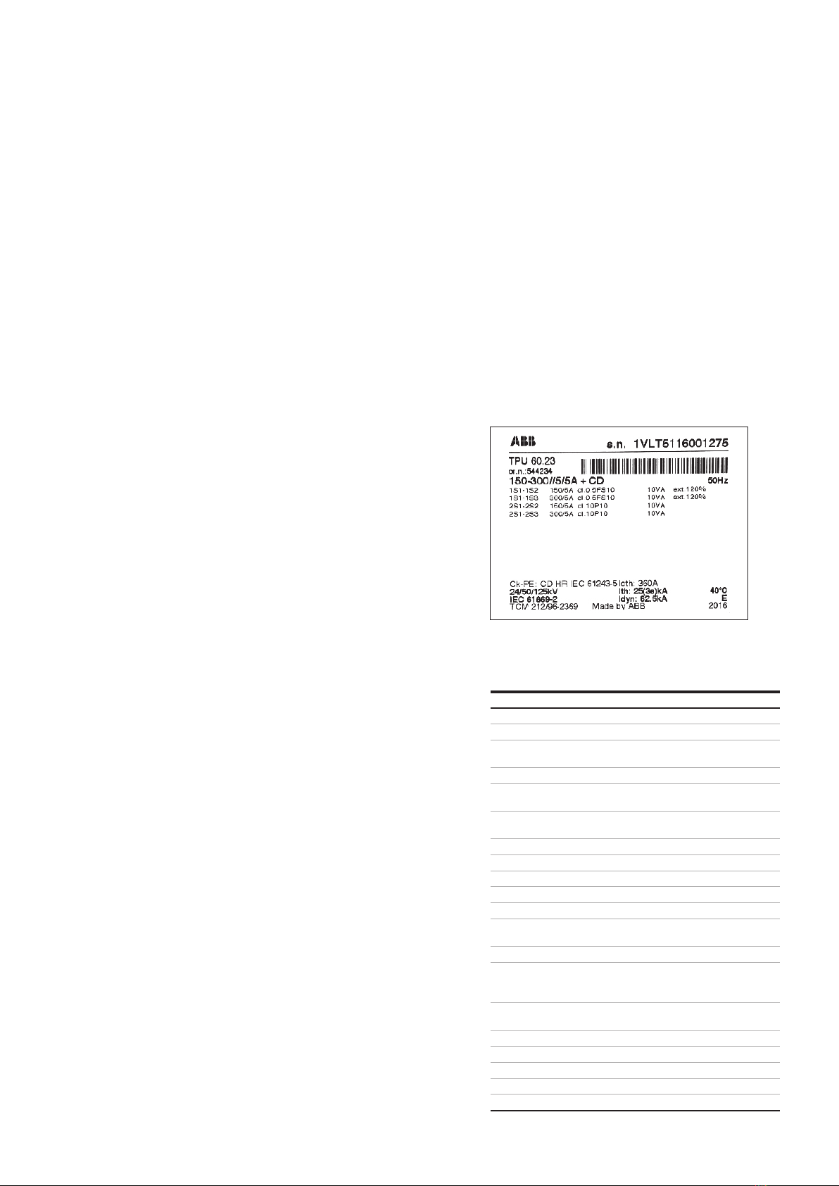
Where:
serial number + barcode
transformer type code
√
√
terminal marking for measuring
secondary winding
terminal marking for residual
accuracy classes
rated output
rated output
rated frequency
ambient temperature
referred standard
Etemperature class
year of production
3. Instructions for installation
General informations
Instrument transformer is an electrical equipment
and the electrical installation shall be done by
skilled person only. National legislation can set
down the minimum age and the criteria for com-
petence of skilled persons working on, with,
or near an electrical installation.
Where is not the national legislation requirements
for competence, the criteria shall be used at least
according to EN 50110-1.
Safety instructions
1. Always consider transformer as a part of the
cir cuit to which it is connected, and do not
touch the leads and terminals or other parts
of the transformer unless they are known to
be grounded.
2. Always ground the metallic bases of instru-
ment transformer.
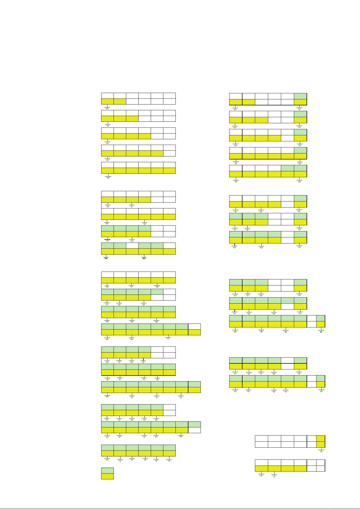
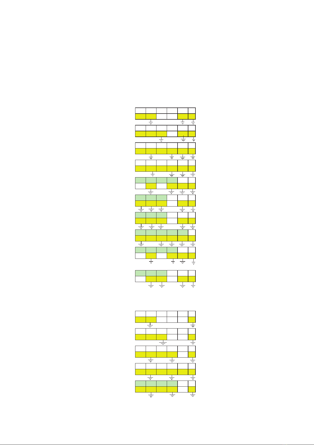
3. Always ground one secondary terminal of the
transformer, except if the windings of voltage
transformer are connected to open delta. Re-
sidual voltage windings connected to open
delta must have dn terminal earthed only on
one of three transformers (earthing screws at
dn terminals of others two transformers have
to be removed). When the secondary of trans-
former is interconnected, there should be only
one grounded point to prevent accidental par-
alleling with system grounding wire. In case of
disconnection from the ground, the ground-
ing screw has to be removed from the second-
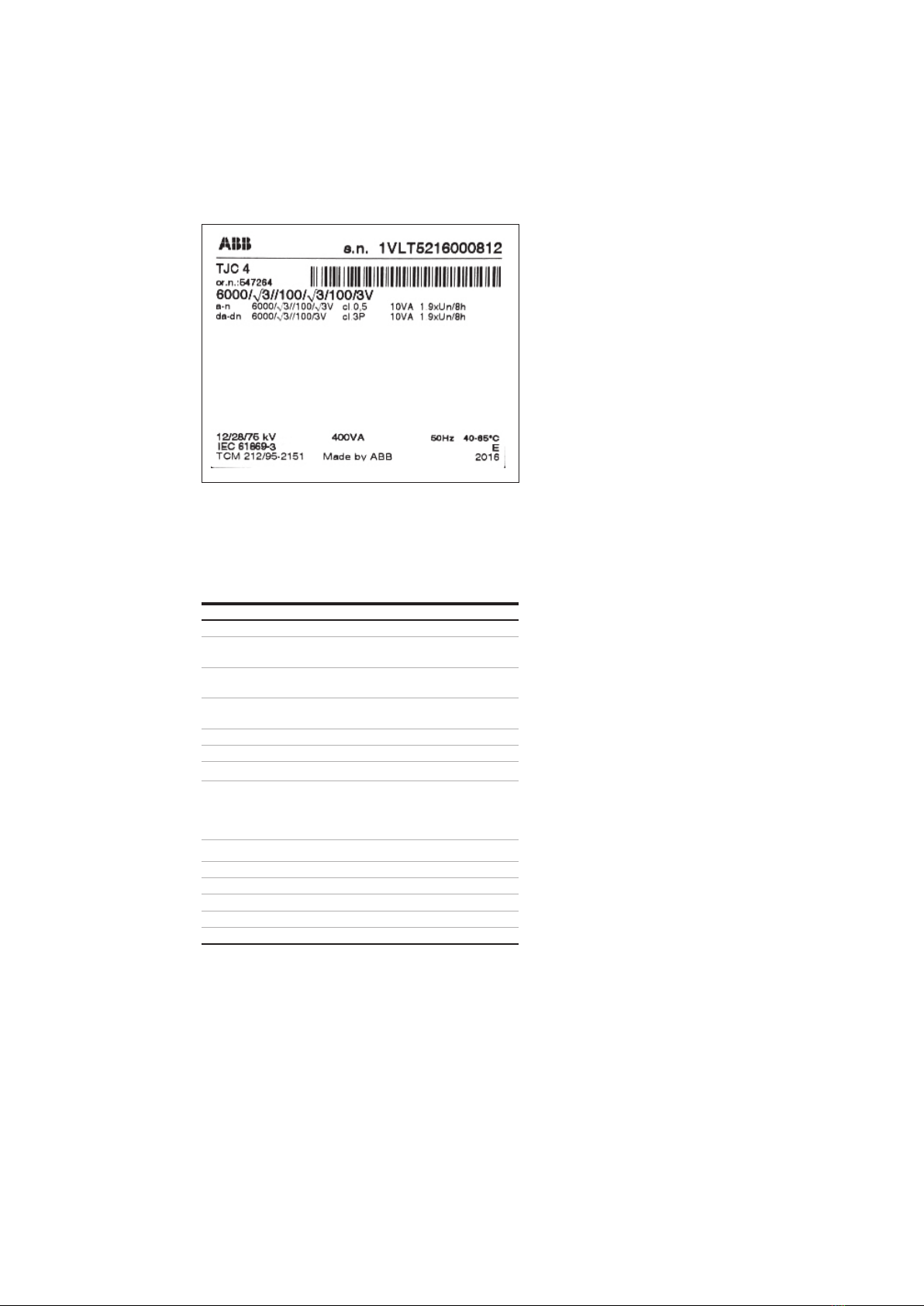
ary terminal. Connection between secondary
terminal and base plate (ground) is shown on
the picture “Crossection of double line termi-
nal box“
4. Always short-circuit the secondary of the cur-
rent transformer, which is not currently in use
to prevent secondary voltages which may be
hazardous to personnel or damaging to the
transformer’s secondary. The secondary like
this must be additionally grounded.
5. Never short-circuit the secondary terminal of
a voltage transformer even this is not in use. A
secondary short-circuit will cause the unit to
overheat and fail in a very short period of
time.
6. Protection of single pole insulated voltage
transformers against feroresonance phenom-
ena is stated in Appendix 3. – Damping of the
ferroresonance in Voltage transformers type
range TJx.
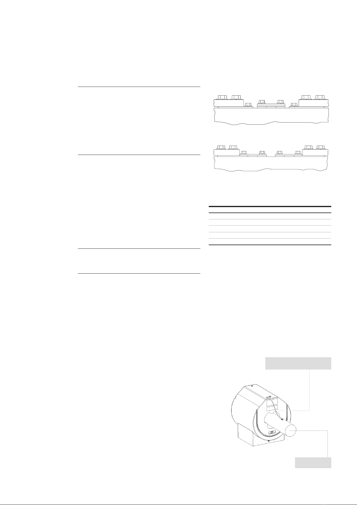
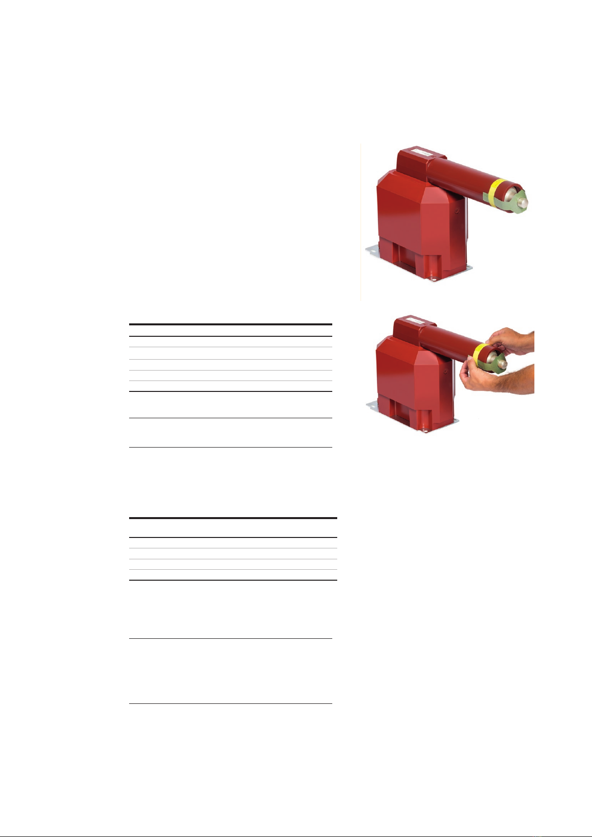
7. In case of the current transformer with volt-
age indication (coupling electrode included) is
secondary terminal box equiped with PE ter-
minal, which is connected with earthing screw
to the base plate, which must be generally
earthed. Connection between secondary ter-
minal and base plate is shown on the picture
“Crossection of single line terminal box“
—
transformer label
—
02


 User manual")