WAC Lighting 9600-TRN-SS User manual

WAC Lighting retains the right to modify the design of our products at any time as part of the company's continuous improvement program. MAY 31, 2016 10:13 AM
waclighting.com
Phone (800) 526.2588
Fax (800) 526.2585
Headquarters/Eastern Distribution Center
44 Harbor Park Drive
Port Washington, NY 11050
Central Distribution Center
1600 Distribution Ct
Lithia Springs, GA 30122
Western Distribution Center
1750 Archibald Avenue
Ontario, CA 91760
1
IMPORTANT:
Read all instructions before installing.
• Read all instructions before proceeding with
the installation.
• This power supply complies with the
requirements of UL1838. This power supply
should be installed in compliance with the
National Electrical Code and local electrical
codes. This unit is for use with landscape
lighting systems only.
• WARNING –Risk of Electric Shock. Install power
unit 5 feet (1.5 m) or more from a pool or spa
and 10 feet (3.05 m) or more from a fountain.
Where the power unit is installed within 10
feet (3.05 m) of a pool or spa connect power
unit to a GFCI protected branch circuit.
• Do not modify or change the product in
any way. This product is to be installed by a
qualied electrician only. Failure to do so will
void the warranty and may result in serious
injury and/or damage to the transformer.
• Connect directly to an outlet; do not use an
extension cord with this product. For 120 Volt
AC operation only. Be sure that the supply
circuit is energized. If this occurs, the circuit
breaker can be replaced with a breaker rated
for high in-rush currents and should only be
done by a qualied electrician.
• To avoid risk of re do not use a xture or a
combinations of xtures where the total watts
exceed the rating of the power supply.
IMPORTANTE:
Lea todas las instrucciones antes de instalar.
• No conecte este temporizador en un cable
de extensión u otro adaptador de corriente.
Conecte directamente a una toma eléctrica.
• No conecte el contador a los aparatos que
contienen
• elementos de calefacción (de aparatos de
cocina, calentadores, planchas, etc.)
• El fallo del temporizador para apagar dicho
dispositivo puede provocar un
sobrecalentamiento y un posible incendio.
• No conecte este temporizador si está húmedo.
• No limpie este temporizador cuando está
enchufado int.
• No exceder los valores máximos del
temporizador.
• Posible riesgo de descarga:
Mantener fuera del alcance de los niños.
IMPORTANT:
Lisez toutes les instructions avant de l’installer.
• Ne branchez pas ce temporisateur dans une
rallonge ou un autre adaptateur électrique.
Brancher directement dans une prise électrique.
• Ne pas relier cette minuterie pour les appareils
qui contiennent
• éléments de chauage (appareils de cuisson,
chaue, un fer à repasser, etc.)
• L’échec de l’horloge pour éteindre tel dispositif
peut entraîner une surchaue et un incendie.
• Ne branchez pas cette minuterie si elle est
mouillée.
• Ne nettoyez pas ce temporisateur quand il
est branché int.
• Ne pas dépasser les évaluations maximales
de la minuterie.
• Risque d’électrocution:
Conserver hors de la portée des enfants.
INSTALLATION GUIDELINES
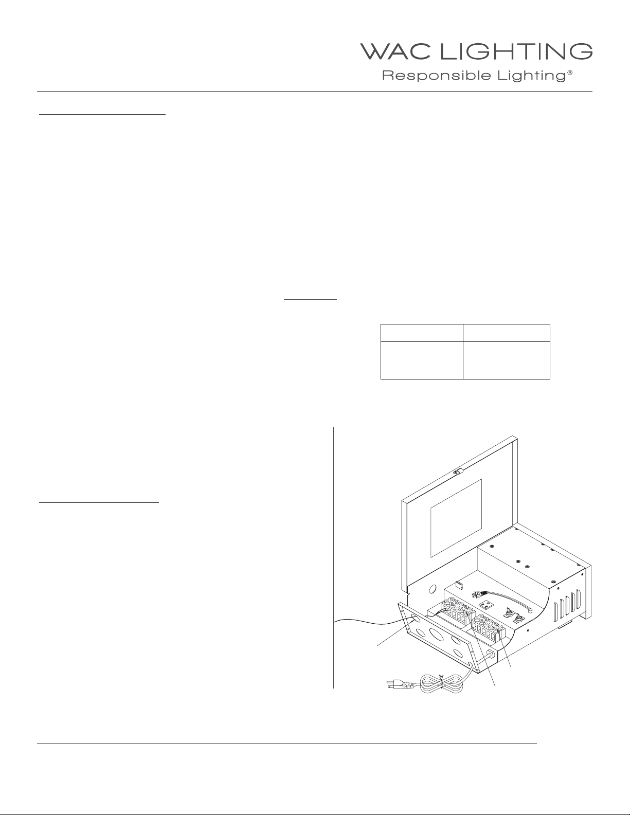
• One or more circuit breakers are included with each transformer. To reset, turn breaker to on position. If circuit breakers trip repeatedly,
have the system inspected by a qualied electrician.
• The transformer includes an internal thermal protector and will run the transformer o if the unit over-heats. The thermal protector will
also automatically reset.
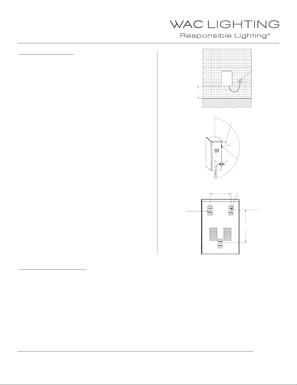
• Where possible, it is best to install the transformer in the center of the lighting installation to minimize long runs reducing voltage drop.
THIS INSTRUCTIONS APPLY TO THE MODEL BELOW:
9600-TRN-SS
INSTALLATION INSTRUCTION
Magnetic Transformer
9600-TRN-SS

WAC Lighting retains the right to modify the design of our products at any time as part of the company's continuous improvement program. MAY 31, 2016 10:13 AM
waclighting.com
Phone (800) 526.2588
Fax (800) 526.2585
Headquarters/Eastern Distribution Center
44 Harbor Park Drive
Port Washington, NY 11050
Central Distribution Center
1600 Distribution Ct
Lithia Springs, GA 30122
Western Distribution Center
1750 Archibald Avenue
Ontario, CA 91760
2
FEATURES AND CONTROLS:
1. Take-apart Stainless steel hinged cover
The cover can be removed for greater access to wiring compartment during installation. To remove, open the door and lift
straight up and o of hinges.
2. Operating instructions on the cover
Refer to these instructions for additional information on specications of the product.
3. Overload circuit breakers
For reliable automatic secondary circuit protection. Circuit breakers may also be used as on/o rocker switches.
4. 1/2” – 3/4” Knockouts
For conduit and accessory mounting.
5. 1/2” – 3/4” Knockouts
For conduit and accessory mounting.
6. Terminal strip
For multiple low voltage cable connections. This transformer is equipped with two circuit breakers that are connected to the
COM. Each circuit can be loaded up to a maximum of 300 watts. You may use one, two, three or all taps at once.
7. Power cord
Heavy-gauge, grounded, water-resistant power cord with integrally molded plug.
8. 120-volt timer module receptacle
For use with optional, removable multi-setting mechanical 24-hour timer or electronic/digital 7-day timer.
9. Photocell plug
For use with photocell, remove jumper and plug photocell here.
INSTALLATION INSTRUCTION
Magnetic Transformer
9600-TRN-SS
` l j =====NOs ======NPs ======NQs=====NRs ===
`vb
1
2
3
4
5
6
7
8
9

WAC Lighting retains the right to modify the design of our products at any time as part of the company's continuous improvement program. MAY 31, 2016 10:13 AM
waclighting.com
Phone (800) 526.2588
Fax (800) 526.2585
Headquarters/Eastern Distribution Center
44 Harbor Park Drive
Port Washington, NY 11050
Central Distribution Center
1600 Distribution Ct
Lithia Springs, GA 30122
Western Distribution Center
1750 Archibald Avenue
Ontario, CA 91760
3
INSTALLATION INSTRUCTION
Magnetic Transformer
9600-TRN-SS
MOUNTING INSTRUCTIONS:
1. Carefully locate and install the power supply so that it is not
in contact with insulation or combustible materials. Provide
minimum of 12 inches of airspace around the power supply.
Transformer must also be mounted a minimum of 12 inches above
grade.
2. Securely mount the power supply to a solid surface using keyhole
slots in the mounting bracket. Drill screw holes at the right
locations and make sure use appropriate screws for the selected
mounting surface.
3. Hang transformer case securely over the screws.
4. Plug in the power cord to a GFCI protected outlet with a cover that
complies with the National Electrical Code for the location.
5. Use appropriate and approved wiring methods to connect the
power supply and the lighting xtures.
6. When using this power supply, the voltage will be reduced and the
current will be signicantly increased.
7. When complete, use the loop on the photocell terminal to
verify that the input current does not exceed the rating of the
transformer.
TRANSFORMER SIZING VA VALUE
Low voltage lighting systems require the use of a transformer to reduce the standard 120 volt power from ordinary household electricity to
the 12 volt needed to power low voltage lamps. Transformers vary in size of capacity. The total lamp VA (load) of all xtures connected to one
transformer must not exceed the VA capacity of the transformer. Therefore, to determine the transformer size needed, simply add up the VA
of all lamps you plan to use.
TRANSFORMER SIZE > TOTAL FIXTURE VA
Select a transformer that matches as closely as possible to your total lamp VA. If you total VA is too great, either divide the total load between
two transformers or use a more powerful model. Selecting a transformer with about 20% higher capacity than you total lamp VA will allow for
adding a xture or two later.
GFCI Outlet
12” Min
Mounting Screws
and Anchors
Keyhole Slots
=
=
5 9/16”
1/4”
1/2”
Keyhole Slot
8 11/16”

WAC Lighting retains the right to modify the design of our products at any time as part of the company's continuous improvement program. MAY 31, 2016 10:13 AM
waclighting.com
Phone (800) 526.2588
Fax (800) 526.2585
Headquarters/Eastern Distribution Center
44 Harbor Park Drive
Port Washington, NY 11050
Central Distribution Center
1600 Distribution Ct
Lithia Springs, GA 30122
Western Distribution Center
1750 Archibald Avenue
Ontario, CA 91760
4
LOW VOLTAGE CABLE LENGTH
In planning a low voltage system, it is necessary to consider the impact of voltage drop. Because of cable’s inherent resistance, voltage drops
along its length: the end-of-run lamps will be dimmer than those at the beginning. Since voltage drop is a function of cable length and cable
size and total xture wattage, voltage drop can be minimized in several dierent ways:
• Use multiple cable runs
• Use heavier gauge cable(8 or 10 gauge)
• Shorten cable lengths or runs
• Reduce VA of individual xtures
• Reduce the total number of xtures on a run
• Use multiple transformers in dierent locations
Cable is measured by gauge. The lower the number, the thicker the cable and the more current it carries. Common cable size for low voltage
lighting is available in three gauges: #12-2, #10-2, and #8-2. To calculate maximum cable length, use the formula below:
Vd=
Vd= Voltage drop in the section of cable, in volts
L = Length of the section of the cable (one way distance), in feet
VA = Total VA values carried by the section of cable for the xtures it supplies
Kc= Cable Constant as follow:
Please refer to WAC Lighting website for voltage drop calculator.
CABLE CONNECTION DETAIL
1. Open the cover of the transformer and remove the Knockouts at
the bottom of the transformer as necessary.
2. Run lighting cables through Knockouts from the bottom of the
transformer.
3. Connect the low voltage cables to the COMs and low voltage
taps labeled on the Terminal Blocks. Make sure that all Cable
Connecting Screws are secure and tight.
L×VA×2
Kc
Cable Size Kc
12
10
8
7500
11920
18960
Terminal Blocks
Cable Connecting Screw
Knockouts
INSTALLATION INSTRUCTION
Magnetic Transformer
9600-TRN-SS
`vb
` l j =====NOs======NPs ======NQs=====NRs ===

WAC Lighting retains the right to modify the design of our products at any time as part of the company's continuous improvement program. MAY 31, 2016 10:13 AM
waclighting.com
Phone (800) 526.2588
Fax (800) 526.2585
Headquarters/Eastern Distribution Center
44 Harbor Park Drive
Port Washington, NY 11050
Central Distribution Center
1600 Distribution Ct
Lithia Springs, GA 30122
Western Distribution Center
1750 Archibald Avenue
Ontario, CA 91760
5
INSTALLATION INSTRUCTION
Magnetic Transformer
9600-TRN-SS
INSTALLING A PHOTOCELL
1. Unplug the transformer from the outlet,
open the enclosure
2. Remove a knockout from the side of the
enclosure, and install the photocell
3. Remove the jumper, plug the photocell
into the socket
4. Position the photocell so that the
operation is not aected by any light
xture.
5. Note: For remote installation, the
L-Bracket can be used to mount the
photocell in desired position.
`vb
` l j =====NOs======NPs ======NQs=====NRs ===
Photocell
Quick Connector
Photocell Conne
Knockout
Photocell
On - Board Installation
9000-PCH-GY
Photocell
Knockout
Mounting Nut
Photocell
Mounting
Nut 1
Mounting Nut 2
L-Bracket
Waterproof Plug
Remote Installation
9000-PCR-GY

WAC Lighting retains the right to modify the design of our products at any time as part of the company's continuous improvement program. MAY 31, 2016 10:13 AM
waclighting.com
Phone (800) 526.2588
Fax (800) 526.2585
Headquarters/Eastern Distribution Center
44 Harbor Park Drive
Port Washington, NY 11050
Central Distribution Center
1600 Distribution Ct
Lithia Springs, GA 30122
Western Distribution Center
1750 Archibald Avenue
Ontario, CA 91760
6
INSTALLING A TIMER
1. Unplug the transformer from the outlet, open the enclosure
2. Unplug the short timer cord inside the enclosure
3. Plug in the timer, plug the short timer cord into the timer
4. Set the timer according to the instructions provided with the time
Short Timer Cord
Timer Plug
Timer
INSTALLATION INSTRUCTION
Magnetic Transformer
9600-TRN-SS
CHECK THE SYSTEM
After installing the entire low voltage system, operate the system for ve minutes. On the low voltage side, all electrical connection spots
should be cool to touch. If a connection is hot to the touch, retighten the connection and check to ensure that the temperature decreases.
Place the transformer cover back and tighten all four provided screws on both sides.
If there’s any irregularities, email or call WAC Lighting“Technical Support” at Sales@waclighting.com, (800)526.2588.
`vb
` l j =====NOs======NPs======NQs =====NRs ===
Table of contents
Other WAC Lighting Transformer manuals