1. Read all instructions.
2. Do not conceal or extend exposed con-
ductors through a building wall.
3. To reduce the risk of fire and burns, do
not install this lighting system where the
exposed bare connectors can be shorted
or contact any conductive materials.
4. To reduce the risk of fire and overheat-
ing, make sure all connections are tight.
5. Do not install any luminaire closer than
6 inches (15.25cm) from any curtain, or
similar combustible material.
6. Turn off electrical power before modify-
ing the lighting system in any way.
7. This transformer is intended for use
with Juno Trac 12 Series or Trac 12/25
Series or Flex 12 Series low voltage
lighting system only and is optimized for
a non-resistive LED load.
8. Install transformer on a wall or other ver-
tical surface.
9. Do not install in confined or unventilated
areas that may entrap heat.
10. Do not allow transformer to come in con-
tact with insulation.
11. Do not install in wet or damp locations or
outdoors.
12. Do not install in a non-accessible loca-
tion. Units are equipped with a manually
resettable circuit breaker that will trip in
the event of a short circuit or overload
condition.
13. Use only 10 or 12 gauge wire to connect
the transformer output to the Trac.
14. MAGXFMR series transformers should
be dimmed only with dimmers specifically
designed for use with magnetic transform-
ers. When used in conjunction with a
non-resistive LED load, these transform-
ers should be dimmed using only dim-
mers qualified for this application by Juno
Lighting Group as listed on Juno speci-
fication sheet, which can be accessed
at www.junolightinggroup.com. Use of
dimmers not qualified by Juno Lighting
Group for this application can result in
flicker, reduced dimming range and erratic
performance. The dimmer must only be
connected to the 277-volt input wires pro-
viding power to the transformer.
15. The unit is equipped with a three input
leads: white (COM), black (277V), and
yellow (BOOST).
16. Do not exceed 12.0V at the first lamp or
exceed the maximum rated wattage of the
transformer.
17. Connect ground wire to the GND terminal.
18. Applying 277 volts across the COM PRI
and 277VAC PRI input terminals will pro-
vide nominal 12 volts across the output
terminals. Applying 277 volts across the
COM PRI and BOOST PRI input termi-
nals will provide nominal 13 volts across
the output terminals.
19. Do not apply 277 volts across the
277VAC PRI and BOOST PRI input
terminals.
INSTALLATION
1. Select a mounting location for the trans-
former, taking care to observe the above
listed safety / operating instructions.
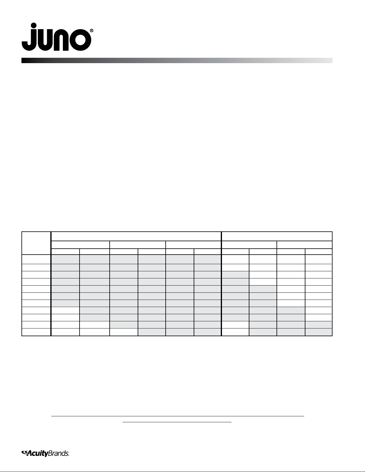
2. Choose the appropriate wire gauge, and
determine the proper wire length and
transformer input, based on the desired
lamp load and the table on the back of this
sheet.
3. Mount the transformer and Trac to the
desired surface. Run AC power lines to
the transformer and output wires from the
transformer to the Trac.
4. In order to avoid nuisance tripping of the
panel circuit breaker, it is recommended
that the use of a high magnetic type circuit
breaker be selected for this and all high
power, magnetic type transformer loads.
5. Connect the input and output wires to the
transformer per the diagram on the case,
information provided on this sheet and
local electrical codes.
6. Connect the other end of the output wires
to the Trac Feed.
7. Ensure that all electrical connections are
tight. This step is essential for a reliable
installation.
8. Install the lamp fixtures onto the Trac.
9. Apply AC power. Confirm that all fixtures
function acceptably. Measure the voltage
at the first lamp. Confirm that the voltage
is between 11.4 and 12 volts.
IMPORTANT SAFEGUARDS:
When using electrical equipment, always adhere to basic safety precautions including the following:
IMPORTANT SAFETY / OPERATING INSTRUCTIONS
INSTALLATION INSTRUCTIONS
Magnetic Remote Mounted Transformers
Single output optimized for non-resistive LED loads
MAGXFMR 1C 20W 277 12AC BL – 12 volt, 0.5W min - 20W max.
MAGXFMR 1C 40W 277 12AC BL – 12 volt, 0.5W min - 40W max.
MAGXFMR 1C 75W 277 12AC BL – 12 volt, 0.5W min - 75W max.
MAGXFMR 1C xxW 277 12AC BL – 12 volt, 0.5W min - xxW max.
SAVE THESE INSTRUCTIONS
WARRANTY
Limited warranty located at:
www.acuitybrands.com/customerresources/terms_and_conditions.aspx
1 of 2
1300 S. Wolf Road • Des Plaines, IL 60018 • Phone 800-323-5068 • Visit us at www.acuitybrands.com/juno-trac
©2017 Acuity Brands Lighting, Inc. Rev 3/17 P2747
Technical Services Phone (888) 387-2212