ABB AT41 Parts list manual

—
PRODUCTS FOR HIGH VOLTAGE APPLICATION
AT Current Instrument Transformer
Instruction for Installation, use and
maintenance

2AT CURRENT INSTRUMENT TRANSFORMER
INSTRUCTIONS FOR INSTALLATION, USE AND MAINTENANCE
—
Scope of Contents
3 1. Service conditions
3 2. Technical details
3 3. Instructions for installation
4 General informations
4 Safety instructions
4 Mounting
4 Connection of transformer
primary side
4 Connection of transformer
secondary side
4 4. Instructions for use
5 Routine test report
5 5. Maintenance instructions
before installation
5 6. Transport & Storage
5 7. Disposal
5 8. Handling
5 9. Normative references
6 10. Dimensions
5 11. Lifetime
5 12. Service
7 Appendix 1.
Examples of outlets
8 Appendix 2.
Dimensional drawings AT35 and
AT41
Dimensional drawings AT38

3
—
Instructions for installation, use and
maintenance for current instrument
transformers
1. Service conditions
The transformers need to be installed in indoor
conditions where the ambient air is not signifi-
cantly polluted by dust, smoke, corrosive gases,
vapor or salts.
The transformers are designed for standard ambi-
ent temperatures between -20°C and +105°C and
altitudes below 1 000 m above sea level. The trans-
formers can also be operated at higher or lower
ambient air temperatures and higher installation
altitudes if such are agreed with the manufacturer.
2. Technical details
Technical parameters and specifications of each
of the transformers are shown on a rating plate
fixed to the transformer body. It is not allowed to
operate the transformer at values exceeding the
rating plate data.
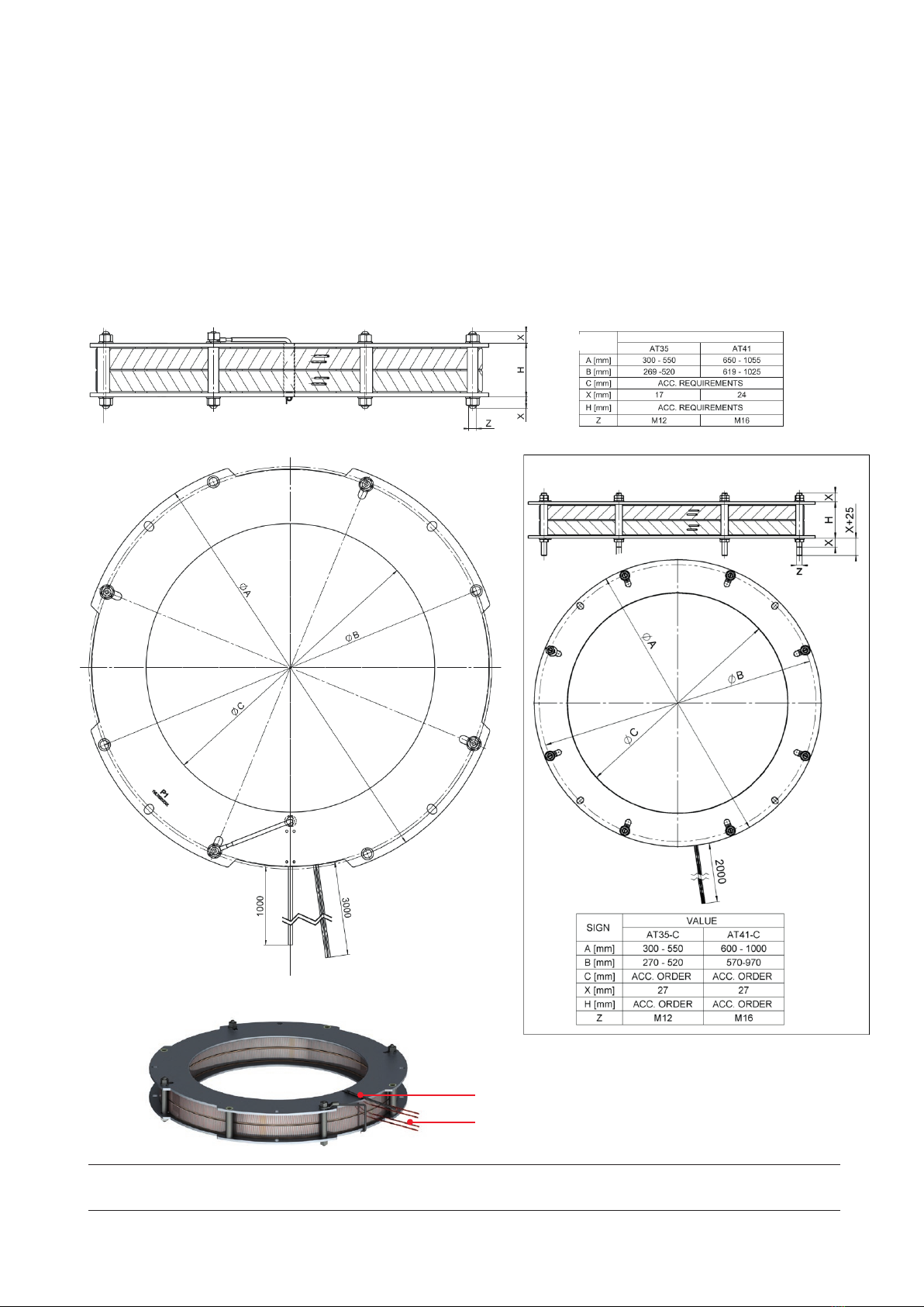
Dimensional drawing of AT transformer is shown
in Appendix 1. Dimensions of the transformer
may vary and depend on required parameters and
the application they are intended for. This is why
the customer is required to specify the highest or
lowest dimensions, in line with the dimensional
drawing in Appendix 1.
Where:
type code of transformer
corresponding standard
rated short-time thermal current
rated dynamic current
rated frequency
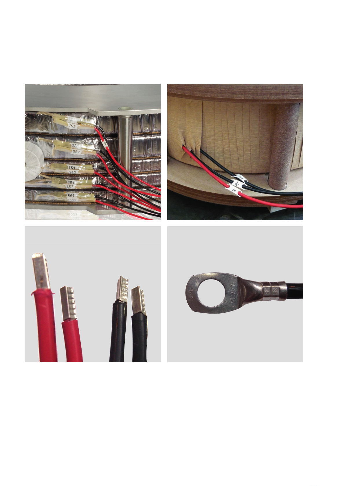
terminal marking for tap of transformer
rated transformer ratio
extended current
accuracy classes
year of manufacture
serial number
Label abbreviation definitions
3. Instruction for installation
General information
Instrument transformer is an electrical equip-
ment and the electrical installation of the instru-
ment transformer can be done by skilled person-
nel, only. The level of experience, age and
eligibility criteria for persons working with, on or
near electric installations is governed by national
legislation. If no such eligibility legislation is avail-
able the corresponding requirements can be
found in EN 50110-1 standard.
Safety instructions
1. Always consider the transformer as a
part of electric circuit which it is con-
nected to.
Don´t touch incoming connectors and
terminals, or any other parts of the
transformer, except you know for sure
these are earthed.
—
01
—
01 Example of rating
plate
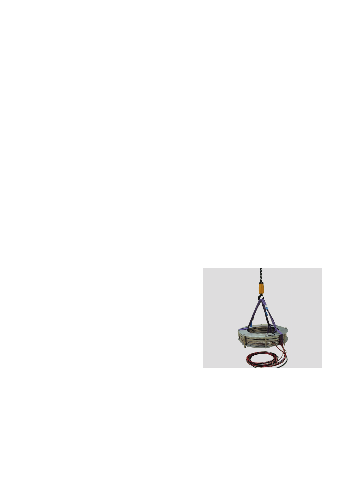
These installation, use and maintenance instructions apply for current instrument
transformers intended for outdoor operation. The instructions refer to current
instrument transformers of the following types:
AT41 – up to 10 000 A; up to 1.2/6/- kV 40 kA(1s) and 100 kA
AT35 – up to 5 000 A; up to 1.2/6/- kV 100 kA(1s) and 120 kA
AT38 – up to 5 000 A; up to 1.2/6/- kV 100 kA(1s) and 120 kA
CURRENT TRANSFORMER
Type: AT41-1055/6701IEC 60044-12
1,2/6/- kV Ith:30(1s) kA3 Idyn:75 kA450 Hz5
201411
Serial:1VLTS11400000712
1S1-1S263 000/1A7ext.120%83 VA9cl.TPY10
Rb=3 Ohm, Kssc=10, Tp=100 ms
C-O-C-O t´-t´al-tfr-t´´-t´´al=100-60-500-100-60 ms
Rct=10 Ohm, Ts=1,00 s, Ktd=27,2

4AT CURRENT INSTRUMENT TRANSFORMER
INSTRUCTIONS FOR INSTALLATION, USE AND MAINTENANCE
—
02 AT35/41 mouting
points
—
03 AT38 mounting
points
2. Ground always the metallic base of the
instrument transformer.
3. Connect always one terminal of each sec-
ondary winding of the transformer to the
earth. When the secondary of trans-
former is interconnected, there should
be only one grounded point to prevent
accidental paralleling with system
grounding wire.
4. Always short-circuit the secondary of the
current transformer, which is not cur-
rently in use, to prevent secondary volt-
ages, which may be hazardous to per-
sonnel or damaging to the transformer’s
secondary. The secondary like this must
be additionally grounded.
Mounting
Mounting points are showed on picture below
The AT transformer is mounted in different
ways-using rings to fix the transformer directly to
the bushing, using flanges, or other ways of fixa-
tion. The mounting is not a part of transformer
delivery and the customer is fully responsible for
installation in the right way.
Tightening torques
The producer has not any liability for incorrect
mounted form or possible consequences of it.
Nuts and threaded rots are delivered on cus-
tomer request.
Connection of transformer primary side
The AT transformers don´t have its own primary
conductor. The primary conductor is designed as
a bushing with its own insulation, or insulated ca-
ble.
Connection of the transformer secondary side
Secondary outlets are marked by color. Which
color is assigned to which wire you can see in ta-
ble below.
Outlets marking
black marked with M
black mark with Ground
screen earth black mark with Ground
black and marked with core/
terminal no.
red and marked with core/
terminal no.
yellow and marked with core/
terminal no.
blue and marked with core/
terminal no.
grey and marked with core/
terminal no.
brown and marked with core/
terminal no.
4. Instructions for use
Current instrument transformers are used:
• to convert large currents in the primary circuit
to an appropriate level for secondary circuit
• to insulate primary and secondary circuit from
each other to protect the secondary equipment
from the harmful effects of large current ap-
—
02
—
03
Mounting points
Lifting points
Mounting points

5
The use of current transformer for other purpose
then described above is forbidden if not agreed
with the producer.
Routine test report
The routine test report of a current instrument
transformer includes:
There are two rating plates available for the trans-
former (one glued on the transformer body, the
On customer request the following information
can be provided free of charge:
• theoretical current/voltage error and phase dis-
•
Additional reports for supplementary charge,
made available on request:
•
•
• additional nameplates (if more than 2 are re-
• verification tests for measuring cores (classes
5. Maintenance instructions
Excessive dust sediments or any other type of
contamination is to be removed from the trans-
former using a soft brush, in a way not to damage
the insulation or cables taken out from the trans-
former.
6. Transport & Storage
Permitted temperature for transport and storage
ranges from -40°C to +105°C. During transport
and storage the transformers have to be pro-
tected from direct impact of solar radiation. The
transformers are delivered in wooden crates or
fixed on transport pallets.
Transported transformers must be protected to
avoid any damages. Right option of transport
must be wisely chosen.
7. Disposal
Materials used in instrument transformers are
considered as materials without environmental
impact and materials are not toxic. Instrument
transformers have to be disposed of in accor-
dance with national legislation relevant to do-
mestic waste disposal.
8. Handling
All the manipulation has to be performed with
great effort to prevent any damage risks. During
manipulation with the hanging strips make sure
that it was used equipment for minimalizing of
cushioned hanging strips, tying direction accord-
ing picture. If necessary place between the strips
and coil/flanges, suitable foam distances to pre-
vent of dangerous pressure to coil. Always check
whether the last insulation layer of the coils is un-
damaged after manipulation. For flanges as well.
9. Normative references
IEC 61869-2 Current instrument transformers
ISO 12100 Machine safety – basic concepts,
general
principles of design
EN 50110-1 Operation of electrical installations
Current instrument transformers are designed,
tested and manufactured in accordance with in-
—
04
—
04 Manipulation with
the hanging strips

6AT CURRENT INSTRUMENT TRANSFORMER
INSTRUCTIONS FOR INSTALLATION, USE AND MAINTENANCE
ternational or national standards, the customer
requirements, based on an agreement between
the customer and the manufacturer. The specific
standard is always mentioned on the transformer
As an example the following standards can be
mentioned:
When agreed, transformers made in accordance
with other standards can also be supplied, or in
accordance with other release version of the
above standards.
10. Dimensions
Dimensions of the current transformers acc. ap-
pendix 2.
11. Lifetime
The product’s lifetime is more than 40 years.
12. Service
After end of lifetime, device must be changed for
new one. There is no service interventions al-
lowed after life time.

7
Appendix 1
Examples of outlets

8AT CURRENT INSTRUMENT TRANSFORMER
INSTRUCTIONS FOR INSTALLATION, USE AND MAINTENANCE
Appendix 2
Dimensional Drawings
—
AT35 and AT41
NOTE: The Length of an outlets (testing primary, secondary outlets) is optional and depends on customer request.
The fixing parts are a part of a delivery, mounting parts can be ordered separately as an attachment.
Testing primary
Secondary outlets
SIGN VALUE
Variant C
length of secondary outlets depending on customer request. The fixing part
are a part of delivery, mounting parts can be ordered separately as and at-
tachment.

9
SIGN
VALUE
NOTE: The Length of an outlets (testing primary, secondary outlets, screening electrodes) is optional and depends on
customer request. The fixing parts are a part of a delivery, mounting parts can be ordered separately as an attachment.
—
AT38
Testing primary
Secondary outlets
Secondary electrodes
1000
1000

1VLM000656 Rev.1, en 2018.07.24
—
NOTE
We reserve the right to make technical
changes or modify the contents of this docu-
ment without prior notice. With regard to
purchase orders, the agreed particulars shall
prevail. ABB does not accept any responsibil-
ity whatsoever for potential errors or possi-
ble lack of information in this document.
We reserve all rights in this document and in
the subject matter and illustrations con-
tained therein. Any reproduction, disclosure
to third parties or utilization of its contents -
in whole or in parts - is forbidden without
prior written consent of ABB.
Copyright© 2018 ABB
All rights reserved
—
CONTACT US
ABB s.r.o.
EPDS Brno
Videnska 117, 619 00 Brno,
Czech Republic
Tel.: +420 547 152 021
+420 547 152 854
Fax: +420 547 152 626
E-mail: kontakt@cz.abb.com
www.abb.com
This manual suits for next models
2
Table of contents
Other ABB Transformer manuals

ABB
ABB TPU Series Parts list manual

ABB
ABB ACS355 series User guide

ABB
ABB RET 541 User manual

ABB
ABB RELION RET670 User manual

ABB
ABB Relion 670 series Quick start guide

ABB
ABB GSB 800 Product manual

ABB
ABB Relion 620 Series User manual

ABB
ABB VT Guard Pro Parts list manual

ABB
ABB ILUJ000004-BLE User manual

ABB
ABB ELK Series Parts list manual
Popular Transformer manuals by other brands

Roland
Roland VT-4 owner's manual

Honeywell
Honeywell NOTIFIER ACT-70 Product installation document

myGekko
myGekko GEK.MEE.ECT.D150 quick start guide

Digital Acoustics
Digital Acoustics IP7-SS40 installation instructions

Audio Note
Audio Note AN-S5 Owner's information manual

Hayward
Hayward AQR100 installation manual