ABB PQFM User manual

—
INSTRUCTION MANUAL
Power Quality Filter PQFM
Installation, operation and maintenance
instructions

2 Table of contents ManualPowerQuality FilterPQFM
—
Table of contents
1Introduction to this manual............................................................................................................... 6
1.1 What this chapter contains..............................................................................................................................6
1.2 Intended audience...............................................................................................................................................6
1.3 Compatibility........................................................................................................................................................6
1.4 Contents.................................................................................................................................................................6
1.5 Related publications............................................................................................................................................7
2Safety Instructions ............................................................................................................................8
3UponReception.................................................................................................................................. 9
3.1 What this chapter contains..............................................................................................................................9
3.2 Delivery inspection..............................................................................................................................................9
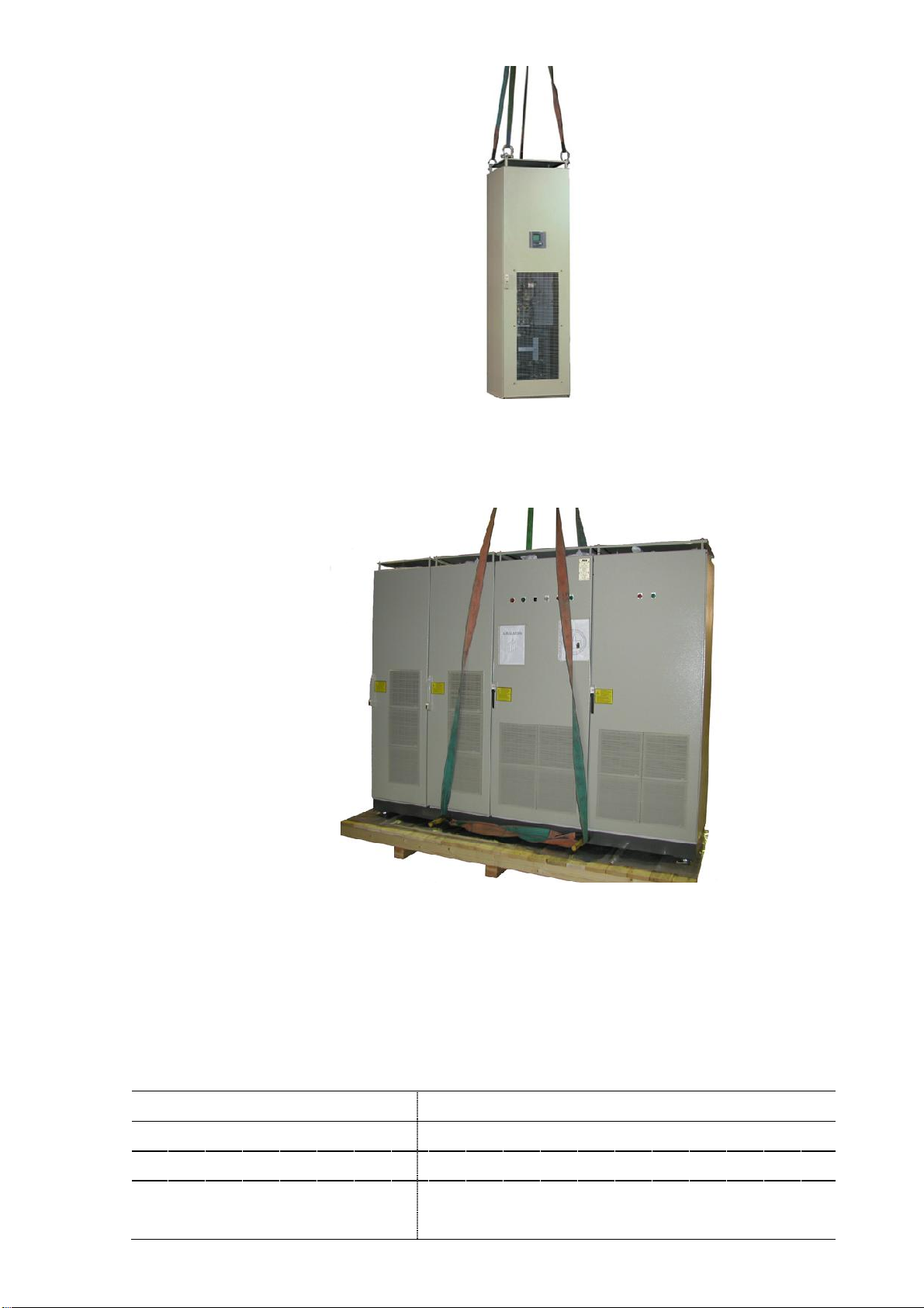
3.3 Lifting and transportation guidelines..........................................................................................................9
3.4 Identification tag................................................................................................................................................11
3.5 Storage...................................................................................................................................................................11
4Hardware description.......................................................................................................................12
4.1 What this chapter contains.............................................................................................................................12
4.2 Typical PQFM filter panel layout....................................................................................................................12
4.3 The PQF current generator hardware.........................................................................................................16
4.4 The PQF main controller...................................................................................................................................17
4.5 The PQF-Manager user interface..................................................................................................................18
4.6 Location of the mainPQFM components..................................................................................................25
4.6.1 Active filtercomponents.....................................................................................................................25
4.6.2 Active filter doorcomponents and protective grid....................................................................30
5Mechanical design and installation..................................................................................................31
5.1 What this chapter contains.............................................................................................................................31
5.2 Installation location requirements...............................................................................................................31
5.3 Airflow and cooling requirements................................................................................................................32
5.4 Standard cubicle dimensions, fixing holes and clearances.................................................................33
5.5 Instructions for mounting IP00 and the PQF-Manager in cubicles...................................................35
5.6 Mechanical interconnection of PQFM cubicles........................................................................................39
5.7 Mechanical preparation of a common cable entry cubicle..................................................................40
6Electrical design and installation.................................................................................................... 42
6.1 What this chapter contains............................................................................................................................42
6.2 Instructions for connecting the PQF-Manager to an IP00 filter system.........................................43
6.3 Checking the insulation of the assembly - earth resistance...............................................................43
6.4 EMC considerations..........................................................................................................................................43
6.5 Earthing guidelines...........................................................................................................................................45
6.6 Selection ofthe power cable size.................................................................................................................47
6.7 Selection ofthe powercable protection/filter input protection scheme......................................50
6.7.1 CE version protection scheme...........................................................................................................50
6.7.2 cULus version protection scheme....................................................................................................52
6.7.3 Contactor type for different unit ratings......................................................................................53
6.7.4 Optional surge arrester circuit (CE version only)........................................................................53
6.8 Connection of the PQFM to the network...................................................................................................54
6.9 Selection ofthe current transformers........................................................................................................56
6.10 Current transformer installation..................................................................................................................59
6.10.1 Basic rules for correct CT installation.............................................................................................59
6.10.2CT locations for the case of global compensation– one feeding transformer.................62
6.10.3CT locations for the case of individual compensation – one feeding transformer..........62
6.10.4CT locations for the caseof global compensation– transformer busbarnot accessible..
.....................................................................................................................................................................63
6.10.5CT locations for the case of two independent feeding transformers..................................64

ManualPowerQualityFilterPQFM Table of contents 3
6.10.6CT locations for the case of feeding transformer and backup generator..........................66
6.10.7CT connections for the case that plain capacitors are present in the network................67
6.10.8CT connections for the case that detuned capacitor banks are installed adjacent but
downstream to the active filter CTs............................................................................................................68
6.10.9CT connections for the case that passive filters and active filters are installedin the
same network.....................................................................................................................................................68
6.11 Electrical interconnection of PQFM cubicles and IP00 plates............................................................69
6.11.1 Mechanical interconnection...............................................................................................................70
6.11.2 Control board cable interconnection...............................................................................................71
6.11.3 Earth points interconnection..............................................................................................................71
6.11.4 CT cable interconnection....................................................................................................................72
6.11.5 Connection of the power stage to the supply.............................................................................. 72
6.12 Electrical connections to the PQF-Manager user interface................................................................. 73
6.12.1 Cabling of remote control functionality.........................................................................................75
6.12.2 Cabling of alarm functionality...........................................................................................................77
6.12.2.1 Alarm outputs.......................................................................................................................... 77
6.12.2.2 Digital outputs.........................................................................................................................80
6.12.3 Cabling of warning functionality......................................................................................................82
6.12.4Cabling of the digital outputcontacts to monitor other filter operation modesthan
warnings and alarms........................................................................................................................................83
6.12.5 Cabling of main/auxiliary control functionality...........................................................................83
6.12.6Implementation of local start/stop buttons................................................................................85
6.13 Electrical connections of filter options and accessories......................................................................87
6.13.1 Externalcommunication with PQF..................................................................................................88
6.13.2 Connection of the Modbus adapter................................................................................................89
7The PQF-Manager user interface.....................................................................................................90
7.1 What this chapter contains............................................................................................................................90
7.2 PQF-Manager user interface description..................................................................................................90
7.3 PQF-Manager overview and navigation.....................................................................................................91
7.4 Icons and main screen......................................................................................................................................91
7.5 The PQF-Manager behavior during filter initialization..........................................................................98
7.6 The PQF-Manager locking facilities.............................................................................................................99
7.7 The PQF start, stop and fault acknowledgement menu.....................................................................100
7.8 The ‘Measurements’ menu............................................................................................................................102
7.8.1 The ‘Overview’ menu...........................................................................................................................102
7.8.2 The ‘System values’ menu.................................................................................................................104
7.8.2.1 Voltages...................................................................................................................................104
7.8.2.2 Line currents...........................................................................................................................106
7.8.2.3 Filter currents.........................................................................................................................107
7.8.2.4 Total filter currents..............................................................................................................108
7.8.2.5 Powers......................................................................................................................................109
7.8.2.6 Temperatures.........................................................................................................................109
7.8.3 The ‘Min-Max logging’ menu............................................................................................................110
7.9 The ‘Settings’ menu.........................................................................................................................................111
7.9.1 The ‘Customer settings’ menu.........................................................................................................112
7.9.1.1 Settings up harmonics, reactive power and filter mode...........................................113
7.9.1.2 Temp unit ................................................................................................................................ 119
7.9.1.3 Activate menu........................................................................................................................119
7.9.1.4 Setting up alarms, warnings and digital inputs and outputs (D I/O)..................120

4 Table ofcontents ManualPowerQuality FilterPQFM
7.9.2 The ‘Commissioning’ menu.............................................................................................................. 122
7.9.2.1 Setting up the network characteristics and the filter synchro mode..................123
7.9.2.2 Setting up the filter characteristics................................................................................124
7.9.2.3 Setting up the current transformer ratios and position..........................................126
7.9.2.4 Setting up the filter rating parameter...........................................................................132
7.9.2.5 Setting up the user’s requirements................................................................................133
7.9.2.6 Commissioning of temperature probes........................................................................134
7.9.3 The ‘Installation settings’ menu......................................................................................................135
7.9.3.1 Setting up the ‘standby’ function....................................................................................136
7.9.3.2 Setting up the ‘auto restart’ function............................................................................138
7.9.3.3 Setting up the system clock..............................................................................................138
7.9.3.4 Setting Password..................................................................................................................139
7.9.3.5 Installation Locking..............................................................................................................139
7.9.4 Set Language ........................................................................................................................................140
7.10 The ‘PQF monitoring’ menu.........................................................................................................................140
7.10.1 The ‘Status of module’ menu...........................................................................................................141
7.10.2 The ‘Filter load’ menu.........................................................................................................................141
7.10.3The ‘Event logging’ menu..................................................................................................................142
7.10.4The ‘Active warnings’ menu..............................................................................................................146
7.10.5The ‘Number of errors’ menu...........................................................................................................146
7.10.6The ‘PQF operation’.............................................................................................................................147
7.11 The ‘User Interface menu..............................................................................................................................148
7.11.1 Manufacturer setting..........................................................................................................................148
7.11.2 About PQF..............................................................................................................................................148
7.11.3 Screen configuration..........................................................................................................................149
7.11.4 Communication....................................................................................................................................150
7.11.4.1 Modbus RTU............................................................................................................................151
7.11.4.2MAC address...........................................................................................................................153
7.11.4.3Ethernet settings..................................................................................................................153
7.11.4.4IP address................................................................................................................................157
8Commissioning instructions ..........................................................................................................159
8.1 What this chapter contains..........................................................................................................................159
8.2 Step 1: Visual and installation check..........................................................................................................160
8.3 Step 2:Setting the address of each unit in a multi-unit filter and terminate the CANbus.....160
8.4 Step 3: Voltage rating check/adaptation and phase rotation check.............................................163
8.5 Step 4: Basic commissioning parameters set up (using PQF-Manager).......................................164
8.6 Step 5: Automatic and manual CT detection procedure ....................................................................166
8.6.1 Automatic CT detection procedure...............................................................................................166
8.6.2 Manual CT detection procedure......................................................................................................166
8.6.2.1 PQF connection diagram....................................................................................................167
8.6.2.2 Material neededand hypotheses for correct measurements................................168
8.6.2.3 Checking the correct connectionof the CTs witha two-channel scopemeter.168
8.6.2.4 Checking the correct connection of the CTs with a Fluke 41B...............................172
8.7 Step 6: Before starting the filter.................................................................................................................172
8.8 Step 7:Start the filter.....................................................................................................................................172
8.9 Step 8: Generate filter load..........................................................................................................................173

ManualPowerQualityFilterPQFM Table of contents 5
8.10 Step 9: Set up the user requirements.......................................................................................................174
8.11 Commissioning report....................................................................................................................................177
8.11.1 Filter identification.............................................................................................................................178
8.11.2 Inspection on site – verification of the active filter after installation................................179
8.11.3 Programming........................................................................................................................................180
8.11.4 Testing (with load)..............................................................................................................................181
8.11.5 Programmed parameters..................................................................................................................182
8.11.6 Comments..............................................................................................................................................184
9Operating instructions ...................................................................................................................185
9.1 What this chapter contains..........................................................................................................................185
9.2 Starting and stopping the filter..................................................................................................................185
9.2.1 Starting the filter with the PQF-Manager....................................................................................186
9.2.2 Stopping the filter with the PQF-Manager..................................................................................188
9.3 Modifying the user requirements...............................................................................................................190
9.4 Changing the system temperature unit and PQF-Manager backlighting.....................................191
9.5 Consulting filter measurements................................................................................................................. 191
9.6 Consulting filter statistics and manufacturer data.............................................................................191
9.7 Filter behavior on fault – retrieving error information........................................................................191
10 Maintenance instructions.............................................................................................................. 194
10.1 What this chapter contains..........................................................................................................................194
10.2 Maintenance intervals....................................................................................................................................194
10.3 Standard maintenance procedure.............................................................................................................195
10.3.1 Step 1: Check the ambient temperature conditions................................................................195
10.3.2Step 2: Record the filter operating status...................................................................................195
10.3.3Step 3: Shut the filter down..............................................................................................................195
10.3.4Step4: Inspect and clean the filter................................................................................................196
10.3.5Step 5: Check the condition of the filter contactors and fuses............................................196
10.3.6Step 6: Check the tightness of the electrical and mechanical connections.....................196
10.3.7 Step 7: Correct any abnormal conditions found........................................................................196
10.3.8Step 8:Restart the filter....................................................................................................................196
10.4 Fan replacement..............................................................................................................................................197
10.5 DC capacitor change......................................................................................................................................198
10.6 DC capacitor reforming(V1 range only, 208V ≤Ue ≤480 V).............................................................198
10.7 Servicing report................................................................................................................................................199
10.7.1 Filter identification............................................................................................................................200
10.7.2Standard maintenance procedure.................................................................................................201
10.7.3Special service actions.......................................................................................................................202
10.7.4Comments..............................................................................................................................................203
11 Troubleshooting guide ..................................................................................................................204
11.1 What this chapter contains.........................................................................................................................204
11.2 Fault treatment procedure..........................................................................................................................204
11.3 Spare part list for normal and dedicated filter servicing..................................................................208
11.4 Troubleshooting guide..................................................................................................................................209
11.4.1 Verification of the PQF-Manager status and the system LEDs............................................209
11.4.2 Fault tracing..........................................................................................................................................210
12 Technical specifications .................................................................................................................223
12.1 What this chapter contains..........................................................................................................................223
12.2 Technicalspecifications................................................................................................................................223

6 Introduction ManualPowerQuality Filter PQFM
—
1Introduction to this manual
1.1 What this chapter contains
This chapter gives basic information on this manual.
1.2 Intended audience
This manual is intended for all people that are involved in integrating, installing,
operating and/or maintaining the PQFM active filter range products. People involved in
the integration, installation and maintenance of theequipment are expected to know
the standardelectrical wiringpractices, electronic components andelectrical schematic
symbols. End users should focus on the Operating instructions (Cf. Chapter 9) and
Maintenance instructions(Cf. Chapter10) of thismanual.
1.3 Compatibility
The manual is compatible with all filters of the 3-wire PQFM-range with PQF-Manager
software versionsorhigher.
−V1 : V26 r3001
−V2 : V11r23
−V3 : V2 r0
−V4 : V0.1 r8
Technical specifications of this product range are given in Chapter 12 of this manual.
This product is not backward compatible with any other PQFx (x: A, B, L, T, I, M, K, S) filter
product.
1.4 Contents
−Chapter1:Introduction to this manual
−Chapter2: Safety instructions
−Chapter3: Upon reception
−Chapter4: Hardware description
−Chapter5: Mechanical design and installation
−Chapter6: Electricaldesign and installation
−Chapter7: The PQF-Manager user interface
−Chapter8:Commissioning instructions
−Chapter9: Operating instructions
−Chapter10: Maintenanceinstructions
−Chapter11: Troubleshooting guide
−Chapter12:Technical specifications

ManualPowerQualityFilterPQFM Introduction 7
1.5 Related publications
−Power Quality FiltersPQFI-PQFM-PQFS Catalogue [English]
−Power Quality Filter, Active Filtering Guide [English]
−PQ-Link Installation anduser’s guide [English]
−PQF Modbus CD [English]
−ABB PQFActive Filters - Raisingsystemreliability to unprecedentedlevels
[English]
−ABB quick start

8 Chapter title ManualPowerQualityFilterPQFI
—
2Safety Instructions
These safety instructions are intended for all work on the PQFM. Neglecting these
instructions can cause physical injury and death. All electrical installation and
maintenance work on the PQFM should be carried out by qualified electricians. Do not
attempt towork on apoweredPQFM.
After switching off the supply to the PQFM, always wait at least 25 minutes before
working on the unit in order to allow the discharge ofDC capacitorsthrough the
discharge resistors.Always verify by measurement thatthe capacitorshave discharged.
DC capacitors may be charged to more than 1000 Vdc.
Before manipulating current transformers, make sure that the secondary is short-
circuited. Never open the secondary ofa loaded current transformer.
You must always wear isolating gloves and eye-protection when working on electrical
installations. Also make sure that all local safety regulations arefulfilled.
DANGER: Toensure safe access, supplies toeachindividualenclosure mustbe isolated
before entry / opening.
WARNING: This equipmentcontains capacitors thatare connected between phase and
earth. A leakage current will flow during normal operation. Therefore, a good earth
connection is essential and must be connected before applying powerto the filter.
WARNING: Stored energy in capacitors: this equipmentcontains capacitors. Checkfor
residual DC voltage before working inside the equipment.
WARNING: There are AC capacitors & DC capacitors connected inside this filter. Before
performing any maintenance work, please short and ground the three line terminals.
The DC capacitor needs 25 mins to discharge afterdisconnection. Please waitfor this
duration before touching any live parts even afterdischarging the AC capacitors to
avoid electricalshock.
WARNING: Neverdischarge DC capacitors through shortcircuit. Always use acurrent
limiting resistor of minimum 100Ω.
WARNING: If the ground is defeated, certain fault conditions in the unit or in the
system to which it is connected can result in full line voltage between chassis and
earth. Severe injury ordeath can resultif the chassis and earth are touched
simultaneously.

ManualPowerQualityFilterPQFM Upon Reception 9
—
3Upon Reception
3.1 What this chapter contains
This chaptergivesbasic information on how toinspect, transport, identify andstorethe
PQFM active filter.
3.2 Delivery inspection
Each PQFM is delivered in an enclosure designed to protect adequately the equipment
during shipment. Upon reception of the equipment, make sure that the packing is in
good condition. Verify the state of the shock and tilting indicators (if mounted on the
enclosure).
After removal of the packing, checkvisually the exterior andinterior of your filter for
transportation damage.
Your filter equipment comes with an information package that is present in a
documentation holder attached at each filter panel. Verify that all documentation is
present, i.e.:
−this manual
−the electrical drawing andconnection diagram
−the communication cable needed for multi-unit operation
For slaveunits,aninterconnection sealand interconnection pads are also provided.
For plateversionsof filter(IP00-versions) the followinghardwarecomponents are also
provided:
−the PQF-Manager user interface with connectionlead;
−optional components.
Any lossor damage should be notified immediately to your ABB representative.
3.3 Lifting and transportation guidelines
Please note that filter equipment weighs hundreds of kilograms. Care should be taken
to ensure that correct handling facilities are used. For individual cubicles the lifting lugs
should be employed.

10 Upon Reception ManualPowerQuality FilterPQFM
Figure 1: Lifting a singlePQF cubicle by using the lifting lugs
For multiple cubicles mounted on a base frame,lifting rods (not provided) shouldbe
used.
Figure 2:Lifting a PQF cubicle assembly by using lifting rods
PQFM-cubiclesmust always be transportedvertically.
Plate versions (IP00) of filters may beliftedhorizontally or vertically. This is done by
attachingliftinghookstotheholesprovidedatthetopandbottomleftandrightcorners
of the IP00 plate.
Table 1: Maximum allowed ambient conditions during transportation
Transportation (in the protected package)
Temperature
-
25 to 70°C (
-
13 to 158°F)
Relative humidity
Max. 95%
Contamination levels (IEC 60721-3-3)
Chemical class 3C3
(a)
Mechanicalclass 3S3(b)

ManualPowerQualityFilterPQFM Upon Reception 11
Remarks
:
(a) Locations with normal levels of contaminants, experienced in urban areas with industrial
activitiesscatteredover the wholearea, orwithheavy traffic.Alsoapplies to locationswith
immediate neighborhoodof industrial sources with chemicalemissions.
(b) Locations without special precautions to minimize the presence of sand or dust. Also
applies to locations inclose proximity to sandor dust sources.
3.4 Identification tag
Each PQFM is fittedwith nameplates foridentification purposes.
For cubicle versions, the main filternameplate islocated atthetop of the master panel
door, at the outside. Other unit identification nameplates may be present atthe inside
of the cubicle.
For IP00 / plate versions of filter, thenameplate is fixed on the top plate ofthe filter
plate.
The nameplate information should always remain readable to ensure proper
identification during the whole life of the filter. The main filter nameplate includes the
filter type, the nominal voltage range and frequency as well as aserial number, the DSP
software version and an ABB internal articlecode.
Before connecting the filter to an already existing master, the DSP and µc software
versions of both filters have to be checked. If the versions are different, contactyour
ABB representative.
3.5 Storage
PQFM packing is made for a storage period of maximum six months (transport time
included fromthe dispatchdateout of the ABBfactory inBelgium). Packing foralonger
storage periodcanbe done onrequest.
If your PQFM is not installed once unpacked, it should be stored in a clean indoor, dry,
dust free and non-corrosive environment. The storage temperature must be between -
25°C(-13°F)and70°C(158°F)withamaximumrelativehumidity of95%,non-condensing.
Table 2:Maximum allowed ambient conditions for storage
Storage (in the protected package)
Temperature
-
25 to 70°C (
-
13 to 158°F)
Relative humidity
Max. 85%
Contamination levels (IEC 60721-3-
3)
Chemi
cal class 3C3
(a)
Mechanicalclass 3S3(b)
Remarks
:
(a) Locations with normal levels of contaminants, experienced in urban areas with industrial
activities scatteredover the whole area, or with heavy traffic.
(b) Locations without special precautions to minimize the presence of sand or dust. Also
applies to locations inclose proximity to sandor dust sources.

12 Hardware description ManualPowerQuality FilterPQFM
—
4Hardware description
4.1 What this chapter contains
This chapter describes atypical PQFM-filtersystemand discusses its maincomponents.
4.2 Typical PQFM filter panel layout
The PQFM active filter is basically composedoftwo parts(Figure 3):
−A filter controllerthat determines the anti-harmonic current tobe injected based
on the line current measurements and the user’s requirements. The line current
measurements are obtained from current transformers (CTs) provided by the
customer. The CTs must be connected upstream of the connection point of the
filter andthe loads. The user enters his requirements by means of the PQF-
Manager user interface. This device also acts as the user’s connection point for
the alarm/warning contacts, the remote control functionality, the other digital
input functionality andthe interface forexternal communication.
−A current generator (power unit) that converts the control signals generated by
the filter controllerintothe filter compensation current. The current generator is
connected in parallel with the load(s). Up to eight powerunits may beconnected
in parallelin one filterunit. Theenclosure(s)containingthe/afilter GUIcontroller
are referredtoas masterunits.The otherenclosuresare referredtoasthe slave
units.In an active filtersystemmorethan one masterunit canbe present.
Compensation current
Current
m
easurements
Non-linear load(s)
- Three-phase
- Single-phase
Supply
PQF
M
Filter panel
PQF main
controller
PQF current
generator 1
PQF Manager
1
2
3
5
4
6
Figure 3:PQFM schematic overviewwith user connections
Theuserconnection description is given in Table 3.

ManualPowerQualityFilterPQFM Hardware description 13
Table 3: User connections for PQFM
Item
User connections
Connection requirement
1
CT connections
Mandatory
2
Power cable connection to the supply
Mandatory
3
Programmable digitaloutputs (warnings…)
Not mandatory
4
Remote control contactconnection or/and local
on/offbuttons or/andmain/auxiliary settings control Not mandatory
5
PQ
-
link
(USB
-
Ethernet)
–
Modbus
RTU
–
ModbusTCP
communication connection Not mandatory
6
Earthconnections from the enclosure toinstallation
earth Mandatory
Note:When a filtersystem consistsof more than onefilter unit, a communication cable
andearth interconnection cable must be installed betweenthe different units.
Mandatory connections are connections that must be present to make the filter
operational. Connections that are not mandatory can be made to enhance the filter’s
basic functionality. For more information on cabling the user connections, please refer
to Chapter6.
Figure 4 shows a typical PQFM master filter panel in CE version.
Figure 5 shows a typical PQFM master filter panel in cULus version.

14 Hardware description ManualPowerQuality FilterPQFM
5
3
1
2
Figure 4: Example ofa typical PQFM master filter panel (CE version)

ManualPowerQualityFilterPQFM Hardware description 15
5
3
1
2
4
Figure 5: Example of a typical PQFM master filter panel (cULus version)
The input/output connections and protection descriptionis given in Table4.
Table 4: Input/Output connections
Item
Input/output connections
1
CT connectionterminals
2
Main power connection
3
Auxiliary fuse protection
4
Filter panel main fuse protection (option for CE version)
5
PQF
-
Manager user interf
ace with connectionterminals foruser I/O (e.g. alarm
contact) and communication interfaces.
For CE-models offilters:

16 Hardware description ManualPowerQuality FilterPQFM
−Up to 8 PQFM master panels can be connectedin parallel providing fullredundancyto
the customer
−In addition to using master panels only, PQFM units can be connected in a master-slave
arrangement.
4.3 The PQF current generator hardware
The power circuit ofa PQFMunitis represented hereafter.
21
3
45
6
7
Preload
resistor
Output filter
IGBT
Inverter
Master Unit
AC power supply
L
L
Figure 6: Power circuit diagram of a PQFM active filter
The description ofthe main components is given in Table 5.
Table 5: Maincomponents of aPQFM active filter
Item
Main components
1
IGBT inverter
2
DC bus capacitors
3
PWM reactor
4
Output filter
5
Preload resistor
6
Main
contactor
7
Auxiliary fuses
Thecurrent generator isphysically organizedin powerunits.Eachfiltercubicle contains
one power unit. A PQFM filter can contain up to 8 power units. Power units can be
combined in a master-slave arrangement orin a master-masterarrangement, the latter
giving full operational redundancy. The current rating of different units in a filter does

ManualPowerQualityFilterPQFM Hardware description 17
nothavetobethesame. Please refertoChapter12for moreinformationon the possible
unit ratings.
In Figure 6 it may be seen that each current generator consists of an IGBT-inverter bridge
(1) that is controlled using PWM-switching technology. Information from the filter
controller is sent to the IGBTs through three flat cables. At the output of the inverter a
voltage waveform is generated which contains the desired spectral components
(imposed by the filter controller) as well as high frequency noise (due to the IGBT
switching technology). Coupling impedance consisting of a reactor (3) and a high
frequency rejection filter (4) ensures that the useful voltage components are converted
into auseful current while the high frequency noise is absorbed. The IGBT-inverter is
equipped with DC capacitors that act as energy storage reservoirs (2).
In active filters containing more than one power unit the control information between
differentunits passes through aCAN control cable.
If a master-master configuration of filter is chosen, all powerunits incorporate a PQF-
Manager display. If a master-slave configuration of filter is chosen, only the master
enclosure contains a PQF-Manager display. All units contain aDC capacitors preloading
resistor (5)which charges the DC capacitors of thefilter unit once the auxiliary fusebox
of the unit(s) is closed. This approach ensures a smooth filter start-up without excessive
inrush currents.
4.4 The PQF main controller
The PQFmain controllercontrols thecomplete active filtersystem. Itstasks include:
−Acceptingand executingcustomer requests to stop andstart theequipment.
−Calculating and generating IGBT-inverter control references based on the line
current measurements andthe user requirements.
−Interface to the IGBT-inverters.
−Measurement of system voltages and currents for control, protection and
presentation purposes.
Figure 7 depictsthe controllerinterface diagram of thePQFM active filter.

18 Hardware description ManualPowerQuality FilterPQFM
PQF
Manager
PQF
Power
Stage
CAN
Bus
Direct Interface
Modbus & PQ-Link interface
Programmable Digital I/O 3∼AC Out
First
unit
Second
unit
User interface
CTsignals
(a)
PQF
main
controller
CAN bus (1)
PQF
Power
Stage
3∼AC Out
PQF
main
controller
PQF
Manager
(b)
(a) CT signals todifferent units (master or slave) mustbe routed through daisy chain principlewith
return path.
(b) If second unitis a slaveunit, it will nothave a PQF-Manager. If secondunit is amaster unit, it will
have a PQF
-
Manager.
CT’s
Figure 7: Controller interface diagramof the PQFM active filter
When the filter consistsof a masterunit only,thecustomerhas to:
−Wire theCTsignals(on adesignated terminal).
−Adapt the auxiliary transformer tapsettings tothe network voltage.
−Connect the AC powerlines and earth connection.
−Set up the installation parameters and user’s requirements with the PQF-
Manager.
He may also want to wire the communication interface (Modbus or Ethernet) and the
programmable digital I/O (e.g. alarm contact,remotecontrol).
When a secondunit is added, it is connectedtothe firstenclosure by means of a CAN
bus communication link (1). In addition, the CT measurements have to be supplied to
each unit, i.e. through a daisy chain link with return path. Also, the earth points of the
different unitshave tobe interconnected.
All slave units have their own AC-connection and main contactor protection.
APQFM activefiltersystemconsistsofupto8 units. Additionalunitstothefirstmaster
unit may be master orslave units. Slave units do not have a PQF-Manager.
4.5 The PQF-Manager user interface
Alluser interactionwith thefilteris channeledthrough the PQF-Manager.
In multi-unit filters consistingof only one master,only themasterhasa PQF-Manager.

ManualPowerQualityFilterPQFM Hardware description 19
In multi-unit filtersconsisting ofmorethanone master,all the masterunitshaveaPQF-
Manager. However, only the PQF-Manager that is connected to the master unit which
has the overall control will be active. The PQF-Manager installed on the units operating
as "slaves" are capable of displaying the relevant information about that specific unit
only. Certain parameters which are specific to that unit (e.g. related to temperature
probes) can be set orchanged locally using the PQF-Manager installed onthatunit. The
PQF-Manager onthe masterunithasa"unit selection" buttonwhichallowstheuser
to select the unit number which he wants to consult. The data then displayed on the
master PQF-Manager is specific to that particular unit number. This unit selection
button is "deactivated" onthe slave Managers. Figure 8 shows the front side of the PQF-
Manager.
Figure 8: Front side of the PQF-Manager
Five main parts can be distinguished(see Table6)
Table 6:Front side of the PQF-Manager
Item
Description
1
Menu display
By navigating through the menus with the , , and
buttons,the filter can be set-up and controlled.On-line help is available by pressing
the button.
2Master/slaves units monitor
3
Locking status /
Alarm
and fan
contact indicator
/
Digital output
contact
indicator
When the PQF-Manager closes one of itsoutput relays, the corresponding symbol
lights up. The digital outputs ofthe PQF-Manager are discussed later inthis section.
4
Filter selection
5
Startstop acknowledgment fault

20 Hardware description ManualPowerQuality Filter PQFM
The PQF-Manager also acts as connection point for external user I/O communication.
Connections are made at the rear side of the PQF-Manager. Figure 9 depicts the
terminals that are present onthe PQF-Manager rearside.
1
2
3
4
5
6
7
89
10
Figure 9:PQF-Manager rear side terminal designation
Theterminal designation is given in Table7.
Table 7: Terminal designation
Item
Customer terminals
1
Digital input 1 and 2
2
Digital outputs 1 to 6 with one common point
3
Alarm outputs (2 outputs withcomplementary signals)
and fan outputs
4
Lockswitch
5
Modbus adapter interface (optional) connection
6
CAN bus connection
interface (routed toPQF
-
Manager connector)
7
Power supply terminals (routed to PQF
-
Manager connector)
8
Ethernet
9
USB
10
Temperature probes
Theterminal explanation isgiven next:
1
Digital input 1 and 2
The digital inputs canbeusedfor threedifferent functions:
−Implementation of remote control functionality;
−Implementation of local on/off buttons (not provided);
Table of contents
Other ABB Water Filtration System manuals
Popular Water Filtration System manuals by other brands

Wilo
Wilo Voda Air Installation and operating instructions

Pondmaster
Pondmaster Clearguard 2700 Care and operating instructions

Leica
Leica EG1120 Instructions for use

Evolution Aqua
Evolution Aqua eazypod Installation & operating instructions

AquaScape
AquaScape BIOFALLS 1000 Instructions & maintenance

Genebre
Genebre 5971 Installation, operation and maintenance manual