AbelCine PCU2+ User manual

PCU2+
Control Unit for Phantom
Owner’s Manual AB-PCU-300
www.abelcine.com
11.04.16 / Firmware v228
AbelCine warrants the PCU2+ to be free of
defects in materials and workmanship for
a period of one year from the date of
purchase.
This warranty does NOT cover:
Damage or malfunction resulting from accident,
misuse, abuse or neglect
Failure to follow the supplied instructions
Repair or attempted repair by a third party
Adjustment, disassembly or modification
of the unit
In case of a warranty claim, contact
the AbelCine service department
888.223.1599 or service@abelcine.com.
www.abelcine.com
11 Warranty
32

The PCU2+ Control Unit for Phantom Cameras
and other Phantom Accessory Products are
designed and manufactured by AbelCine.
The PCU2+ is a Non-Consumer, Industrial Product.
www.abelcine.com
3
PCU2+

Periodically, firmware updates are released that
add features, enhance functionality, and fix bugs.
Firmware updates and revisions to this manual are
available from:
http://www.abelcine.com/r/pcu2-plus-updates
Updates
1 Introduction 6
2 Basics of Operation 8
3Record Mode 10
4Playback Mode 17
5Advanced Menu 19
63D Control 23
7Wireless Operation 24
8Connectors and Battery 26
9Specifications and Maintenance 29
10 Warnings 30
11 Warranty 32
Contents
5

Thank you for purchasing the PCU2+ Control Unit
for Phantom Cameras.
The PCU2+ is a controller that is compatible with
most Phantom high-speed cameras. In addition
to controlling a Phantom without a laptop, the
PCU2+ can control two Phantoms simultaneously
in a stereo 3D configuration.
e PCU2+ has an integrated Bluetooth transmitter,
and when paired with a Vision Research
Bluetooth dongle, it can control a Phantom
camera from a distance of up to 100 meters
(unobstructed).
e PCU2+ can be powered by the camera
and also has an internal Lithium Ion battery
for wireless use.
1 Introduction
6
Mounting
Holes
V-Lock
7
Mounting Options
e PCU2+ provides five mounting options:
two 1/4-20 holes on the top, two 1/4-20
holes on the bottom, and one V-Lock on
the back.

2 Basics of Operation
The PCU2+ has two main modes of
operation, Record Mode and Playback
Mode.
Record Mode enables you to edit the
recording parameters and control
the recording process. The PCU2+
starts in Record Mode.
Playback Mode allows you to control video
playback and save clips to a CineMag or
other media.
For more details about Playback Mode,
see page 17.
TRIG
Sends a trigger signal
to the camera(s).
EXIT
In Playback Mode,
hold to return to
Record Mode.
Buttons
PREV Goes to the previous screen of
parameters. In Playback Mode, skips to
previous clip or to first frame of current clip.
ADV In Record Mode, hold PREV to enter
Advanced Menu.
LOCK Hold PREV and NEXT to
lock/unlock the PCU2+. When the
PCU2+ is locked, you can monitor
the camera’s state but no
parameters can be changed and no
functions can be performed.
NEXT
Goes to the
next screen
of parameters.
Hold to view
information
about the camera
connected
to CAM 1.
In Playback Mode,
skips to next clip
or to last frame
of current clip.
REC
Starts recording. If there is already a clip in
the camera’s RAM, hold for three seconds
to erase the clip and start a new recording.
SAVE
In Playback Mode, saves marked portion
of current clip in RAM to CineMag or other
media.
BB Performs a black balance.
WB Performs a white balance.
A
So Keys
B
C
So Keys
D
LEFT VI EW FRON T VI EW RI GH T VI EWLEFT VI EW FRON T VI EW RI GH T VI EW
WIRELESS
REC LED
Illuminates when
the camera is
actively writing
images to its RAM.
When the PCU2+
is o, the LED
indicates charging.
8 9

Clip # when in Playback mode
(displays Mif playing from CineMag)
LEFT VI EW FRON T VI EW RI GH T VI EWLEFT VI EW FRON T VI EW RI GH T VI EW
WIRELESS
In Record Mode, the PCU2+ will show up
to four parameters on the screen at once.
The parameters can be accessed for
editing by pressing the corresponding so
keys to the le and right of the screen.
The so key for a parameter with a wide
range of values, such as frame rate,
will enter Edit Mode on a new screen
(see page 12). The so key for a parameter
with very few potential values will toggle
through the options.
So Keys
Press to
edit value
So Keys
Press to
edit value
3 Record Mode
The top line of the screen in Record
Mode displays the recording mode
(Loop or Run/Stop) and playback status
(Live or Playback). There are also
recording and HQ mode indicators.
The maximum length of the current
shot in frames and real time are displayed
on the bottom of the screen.
Recording Mode
Loop or R/S
REC shows while camera is
recording
Active partition #
Clip length in frames
Camera is in HQ mode
Clip length in seconds
(real time at current frame rate)
Playback Status Lfor live or Pfor playback
Battery Icon
Battery is charging
10 11

LEFT VI EW FRON T VI EW RI GH T VI EWLEFT VI EW FRON T VI EW RI GH T VI EW
WIRELESS
+
Increment value
by 1 (hold for
fast change)
Set
Set value and
exit Edit Mode
Editing a Parameter
While in Record Mode, the PCU2+ can enter
Edit Mode by pressing the so keys.
Many parameters have a series of preset
values that can be accessed by pressing
the PREV and NEXT buttons in Edit Mode.
When the parameter is at the desired value,
press Dto set value and exit Edit Mode.
–
Decrement
value by 1
(hold for fast
change)
PREV
Jump to
lower preset
NEXT
Jump to
higher preset
3 Record Mode
Shooting Parameters
A- FPS: Edit frame rate in frames per second.
B- Sht: Edit shutter angle.
C- Resolution: To select a standard
resolution value, use PREV or NEXT to
move the cursor over the xand change
the paired resolution values with Aand C,
corresponding to +and –. To change the
horizontal or vertical pixel count
separately, select each with PREV or NEXT
and adjust with +and –.
D- Trg: Edit trigger point relative to the shot
length; 0% represents the tail of the shot,
100% represents the head.
12 13
Note: On cameras with
a built-in capping shutter,
changing FPS, shutter angle
or resolution will cause the
PCU2+ to trigger a black balance
aer a 3 second delay,
unless AutoBB is disabled
in the Advanced Menu
(see page 22).

V16 ISO Screen
A- Gain: Adds gain to video output,
increasing exposure at the cost of
highlight latitude.
B- Gam: Adjusts gamma from a range of 1.0
to 4.0. The default is 2.2. On the Flex4K
Log mode can be toggled in the Gamma
set screen.
C- EICV: Adjusts sensitivity by applying
a tone curve. is is the preferred method
of setting ISO.
D-TOE: Changes exposure by raising the
video level primarily in the shadows.
1.00 is the default and lowering this value
raises the shadow levels.
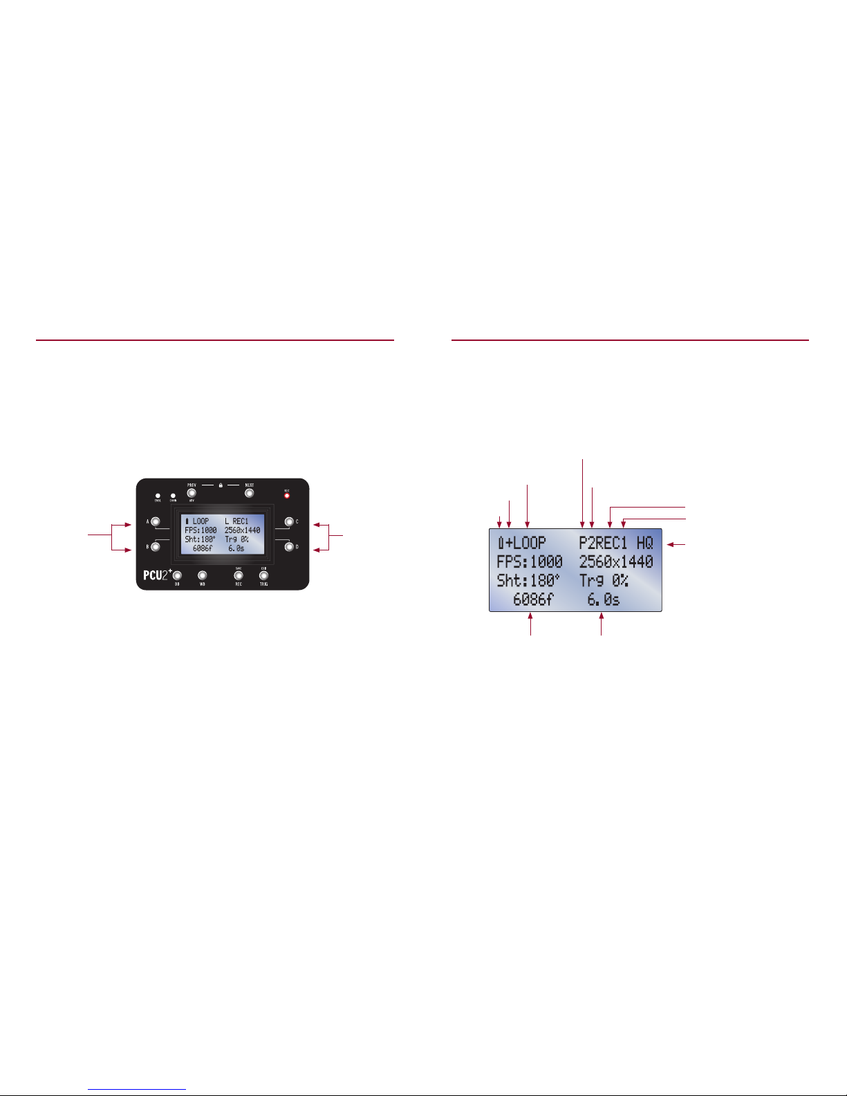
3 Record Mode
V16 Video Output Parameters*
A- ISO: Opens a sub-page (see next column)
for editing all values that aect the
camera’s sensitivity, including Gain,
Gamma, Tone Curve and Toe. e
displayed number reflects the eect of all
parameters.
B- Gam: Adjusts gamma from a range of 1.0
to 4.0. The default is 2.2. On the Flex4K
Log mode can be toggled in the Gamma
set screen.
C- WB: Adjusts white balance in degrees
Kelvin. is setting aects the blue-red
axis of white balance only. is value will
update automatically when performing an
auto white balance.
D-CC: Adjusts the green-magenta axis of
white balance. e color compensation
value will update automatically when
performing an auto white balance.
* e Miro 320, V1610 and newer cameras
including the Flex 4K and VEO use the
V16 protocol. See page 15 for legacy camera
protocol.
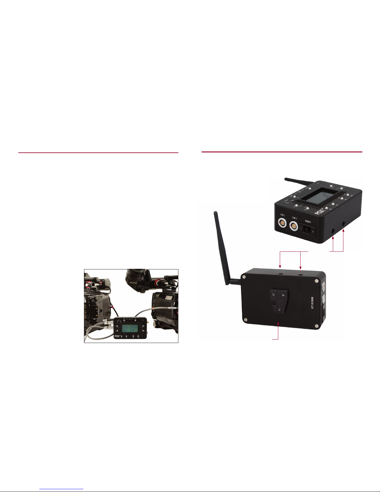
Camera Cooling Parameters
A- CamTemp: Camera temperature
in Celsius. Press to edit target temp.
B- SnsTemp: Sensor temperature in Celsius.
Press to edit target temp.
C- Fan: Displays fan speed as a percentage
of total power.
D-TE%: Displays sensor cooler power.
14 15
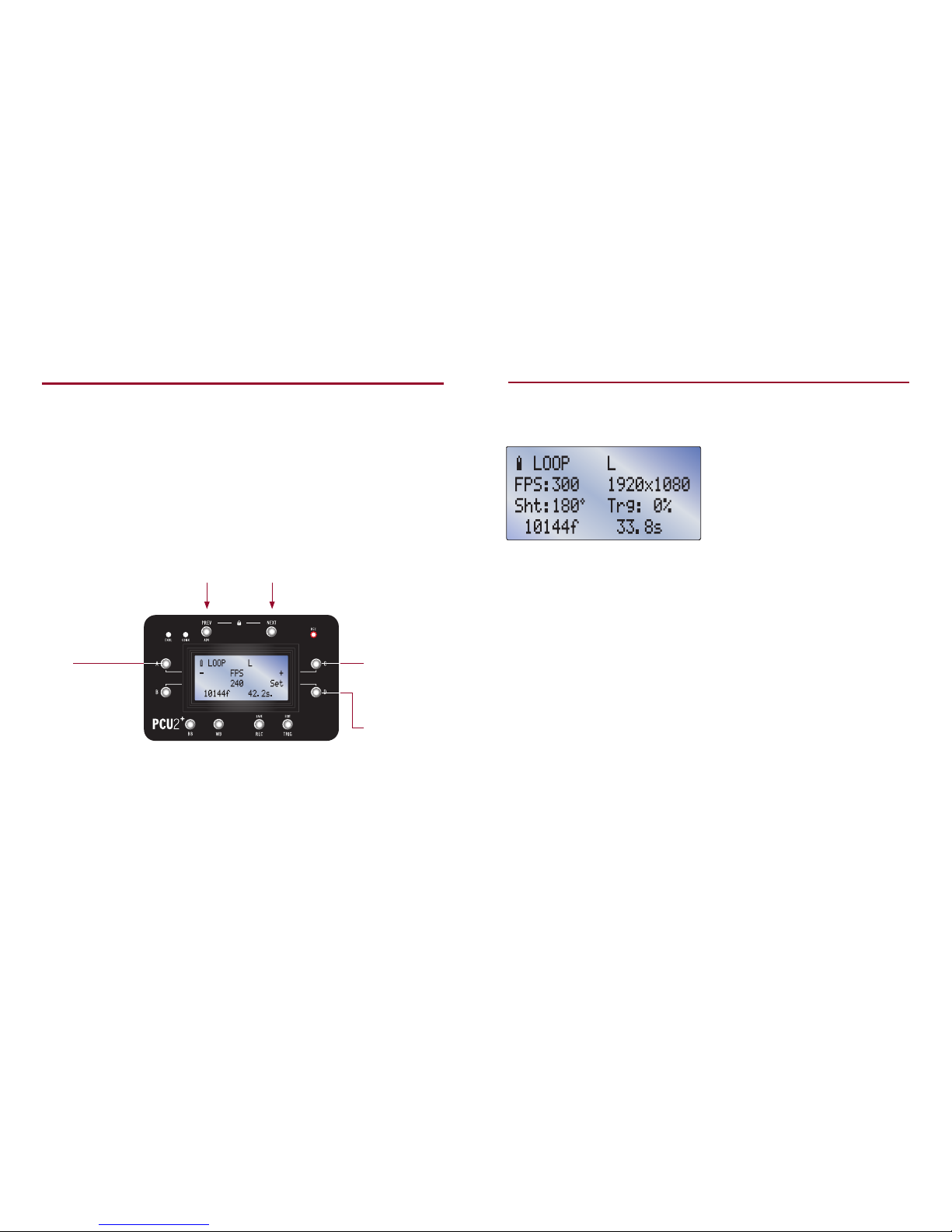
Legacy Video Output Parameters
A- Gain: Adjust the gain of the video signal,
between 1.0 and 5.0.
B- Gam: Adjust gamma from a range of 1.0 to
4.0. The default is 2.2.
C- Chr: Adjust the chroma level between 0
and 3.0.
D- Hue: Shi the image color towards green
or magenta. The default is 0.
Note: On newer cameras the V16 video
Output Parameters will be seen instead
(see page 14).

A- PB: Toggle between Playback Mode (PLAY)
and Record Mode (LIVE).
C- Mode: Toggle between four record modes:
1 LOOP records continuously to RAM,
replacing old frames with new ones as
memory is filled.
TRIG stops recording, based on set
trigger point (see page 13 to check your
setting).
2 R/S RUN/STOP Records directly to a
CineMag.
REC begins recording, and TRIG stops
recording.
3 A.PL/R AUTOPLAYBACK & RECORD
Records in Loop Mode.
TRIG automatically plays back each clip
once, returns to Record Mode, and
erases the clip. Applicable when using an
external recorder.
4 CONT CONTINUOUS RECORD TO MAG
Records in Loop Mode.
TRIG auto-saves each clip to the
CineMag, automatically returns to Record
Mode and erases the clip from RAM.
D- PTNS: Hold to partition RAM.
Partitioning RAM will instantly erase any
clips currently in RAM.
Other Parameters
3 Record Mode
LEFT VI EW FRON T VI EW RI GH T VI EWLEFT VI EW FRON T VI EW RI GH T VI EW
WIRELESS
Last frame
of current clip
To review or save footage, enter Playback
Mode by toggling the ‘PB’ parameter (A)
from LIVE to PLAY. If the camera is already
playing back but the playback controls
aren’t visible on the PCU2+, press CTL (B).
B - CTL
Access playback controls
A- PB
Toggles between
LIVE and PLAY
First frame
of current clip
Marked In Point Marked Out Point
Source of clip
(RAM or Mag)
Current frame
Clip number
4 Playback Mode
Once in Playback Mode, the first and last
frames of the current clip are displayed
on the top line. Marked frames appear
on the bottom line.
16 17
A- Zoom: Toggle video-out zoom state.
B- PA: Set frame lines (production area)
to a percentage of frame size or to certain
fixed aspect ratios.
C- VF/OSD: Toggle On Screen Display
for viewfinder.*
D-SDI/OSD: Toggle On Screen Display
for SDI output.
* Note: For LC cameras
(with a built-in LCD screen),
Cwill toggle between SDI,
LCD, and O.
Video Output Toggles

LEFT VI EW FRON T VI EW RI GH T VI EWLEFT VI EW FRON T VI EW RI GH T VI EW
WIRELESS
PREV
Jumps to previous clip
or first frame of current
clip (cycles through RAM
and CineMag)
SAVE
Saves the marked clip
in RAM to CineMag or
other media
EXIT
Hold to exit Playback Mode
*(double-click to switch to
single-frame playback mode)
<
Plays in reverse
or pauses
(hold to play fast)
>
Plays forward
or pauses
(hold to play fast)
Playback Control
Clips can be played back from RAM or from
a CineMag. Clips in RAM can be trimmed
and saved to a CineMag.
*Single-Frame Playback Mode
A= -1 (Moves video backward by one frame.
Hold to play backwards at half speed.)
C= +1 (Moves video forward by one frame.
Hold to play at half speed.)
Exit = Hold to exit Playback Mode.
Double-click to enter/exit single-frame
playback mode.
[
Marks In Point
(hold to clear In Point)
]
Marks Out Point
(hold to clear Out
Point)
NEXT
Jumps to next clip or last
frame of current clip (cycles
through RAM and CineMag)
Note: With cameras
set to record and play
simultaneously, the
playback controls will
always need to be manually
selected with the CTL
option. Likewise, exiting
the controls will not exit
Playback Mode – this
must be done by switching
from PLAY to LIVE
(see page 16).
4 Playback Mode
LEFT VI EW FRON T VI EW RI GH T VI EWLEFT VI EW FRON T VI EW RI GH T VI EW
WIRELESS
B- Switch to
next parameter
Parameters that need to be changed
less frequently are accessible in the
Advanced Menu.
Note: Only parameters
that pertain to the
currently used camera
model will be visible
in the Advanced Menu.
D- Edit
parameter
ADV
Hold PREV for several
seconds to access
Advanced Menu
5Advanced Menu
18 19

Video System
Press Dto toggle through all video output
formats supported by the Phantom.
On the Flex4K Dwill open the following screen
for setting video options
Erase Mag/Storage
Playback Rate
The Phantom will normally play at the video
system frame rate. Change the playback rate
with C and D. This setting is persistent over
power cycles.
Parameters in the Advanced Menu
5Advanced Menu
Hold Dfor five seconds to initiate erasure of
CineMag or other media.
• Dual Toggles between unified output (UNI)
and simultaneous Live + Playback (L/P).
• 3G Toggles between 3G O, 444, 60P and
4K modes.
• Sys Cycles through all supported video
formats compatible with the current 3G
mode.
Video Mode Mag Format (for Flex4K only)
For cameras with two SDI outputs, press Dto
toggle between video modes 4:2:2, dual-link
4:4:4, and 4:2:2 with simultaneous live and
playback.
HQ Mode (for Flex 2K only)
Press Dto toggle HQ mode.
Parameters in the Advanced Menu
º LOOP L
Advanced
Mag Format:Cine Raw
10144f 33.8s
Press Dto toggle between Raw and ProRes
recording on CineMag.
FPS Presets
Toggles frame rate presets between NTSC
(24/30 multiples) + PAL (25 multiples).
20 21

Auto BB (Automatic Black Balance)
Press Dto toggle Auto BB. Only for cameras
with a built-in capping shutter. PCU2+ initiates
a black balance when a change in parameter
requires it. is setting is persistent over
power cycles.
iload (reset cam)
Press Dto load camera’s factory settings.
Desqueeze
Press Dto toggle Desqueeze. On supported
cameras, this corrects the video output when
the camera is used with 2:1 anamorphic
lenses.
F Stop
When a camera has a lens mount and lens
that support electronic control of the f-stop
(such as the Canon EF mount), the aperture
can be increased or decreased by pressing
C and D.
5Advanced Menu
Setup 3D
Disable 3D Sync
Pressing D enables external frame sync on
one camera, genlock on both (if available),
and copies all CAM2 settings from CAM1.
Pressing D sets frame sync to internal and
disables genlock on both cameras.
When two cameras are connected, the
PCU2+ always sends all commands to both
cameras, enabling synchronized stereo
recording and playback. There are two
additional functions in the Advanced Menu
for setting up and breaking down dual
camera synchronization.
Note: For guaranteed
matching in and out points,
we recommend using a
trigger hard-wired to the
trigger ports of each camera.
For proper sync, FSYNC must
be connected between the
two cameras, and a
connection should be made
between Timecode Out of
one camera and Timecode In
on the other.
63D Control
22 23

BT: Not Paired
Hold Dfor 5 seconds to begin
searching for cameras within range.
Note: e name shown for each
camera is the MAC address printed
on the side of the Bluetooth dongle.
Technically the PCU2+ pairs with the
dongle, not the camera.
To pair the PCU2+ with the camera shown,
press D. To exit without pairing, press B.
BT: Pairing
e PCU2+ will remember the most recently
paired dongle and will automatically connect
when it is within range. If you need to connect
to a dierent dongle, establish a link in the
next page.
Aer several seconds of searching, a
connection screen will appear showing the
first camera found (if any). If more than one
camera is found, press Cto see the next
camera.
BT: Paired
e PCU2+ can wirelessly control a
Phantom camera from a distance of
up to 100 meters when used with a
Vision Research Bluetooth dongle.
7 Wireless Operation
LEFT VI EW FRON T VI EW RI GH T VI EWLEFT VI EW FRON T VI EW RI GH T VI EW
WIRELESS
WIRELESS
ENABLED LED
Illuminates when
Bluetooth is enabled.
When Bluetooth
is enabled, wired
operation is not
possible.
To enable Bluetooth, go to the ‘Bluetooth’
page of the Advanced menu. e blue LED
labeled ENBL will illuminate to indicate
that Bluetooth is turned on.
Press D to toggle Bluetooth. When
Bluetooth is enabled, the wired camera
connection is disabled.
Make sure the antenna is screwed on and
internal battery is charged. When the
PCU2+ is not powered from a cable, the
internal battery will provide power for up
to 30 continuous hours on a full charge
(see page 27).
WIRELESS
CONNECTED LED
Illuminates when
there is an active
connection between
the PCU2+ and the
Bluetooth dongle.
24 25

ACAM 1
Primary camera connection. Powers the PCU2+ and
simultaneously charges the internal battery.
B CAM 2
Secondary camera connection.
In 3D use, the master camera should be connected to
CAM1 and the slave camera should be connected to CAM2.
All commands will be sent simultaneously to both cameras.
C Power Switch
Turns PCU2+ on and o. When the PCU2+ is not on a wired
connection, turn the PCU2+ o whenever possible in order to
conserve the battery charge.
D Battery Charger Port
is connection is for powering the PCU2+ and charging the
internal Lithium Ion battery. e internal rechargable battery
allows for over 30 hours of continuous wireless operation. Use
only the supplied power supply with the PCU2+.
E Update
Firmware updates can be sent through the mini-USB-
compatible port. e PCU2+ can be powered through this
connection as well, but the internal battery will not be
charged.
F Antenna
For Bluetooth. When using a wired connection, this antenna
may be removed by unscrewing it.
8 Connectors and Battery
A B
EF
C
D
26 27

Maintenance
To be notified of necessary firmware updates,
please register your PCU2+ at
www.abelcine.com/r/pcu2-registration.
ere are no user serviceable parts in this device.
Avoid moisture and exposure to extreme temperatures.
To clean the enclosure, carefully spot clean with
alcohol, only as necessary.
Specifications
9 Specifications and Maintenance
Operating Conditions 32° – 104°F
0 – 85 % relative humidity
Weight 18.2 oz
Dimensions 5.19 x 3.1 x 1.82 inches (w/o antenna)
Bluetooth Range 100m (unobstructed)
Bluetooth Frequency 2.4 GHz
FCC ID of Radio e FCC ID of the bluetooth module is: T9JRN41-3
e IC (Canada) ID is: 6514A-RN413
28 29

When using this device, basic precautions
should always be followed, including:
1 Read all instructions before using the PCU2+.
2 Use only with Vision Research cameras with a built-in Remote port,
or with an adapter device or cable approved by AbelCine, Inc.
3 Use only with cables manufactured by or approved by AbelCine, Inc.
4 Do not use the PCU2+ with a damaged cable, or connected to a damaged camera.
5 Do not replace the internal battery. For battery replacement please contact AbelCine.
6 Use only the battery charger included with the PCU2+ or a replacement supplied
or approved by AbelCine, Inc. to charge the internal battery.
7 Do not open the PCU2+. ere are no user-serviceable parts inside.
8 To reduce the risk of electrical shock, do not use the PCU2+ when wet.
10 Warnings
30 31
Table of contents
Popular Control Unit manuals by other brands

Task Force Tips
Task Force Tips Ball Intake Valve Instructions for installation, safe operation and maintenance

Arbor Technology
Arbor Technology EmETX-a55E0 Quick installation guide

MKS
MKS HPS 145 Vacuum Sentry Series Operation and maintenance manual

Vag
Vag GA INDUSTRIES FIGURE 925 Installation, operation and maintenance manual

Viessmann
Viessmann 5547 Operation manual

Sony
Sony SX-M700 Service manual