manuals.online logo
Brands
  1. Home
  2. •
  3. Brands
  4. •
  5. XBee
  6. •
  7. Control Unit
  8. •
  9. XBee S1 User manual

XBee S1 User manual

Exploring XBees and XCTU a learn.sparkfun.com tutorial
Available online at: http://sfe.io/t353
Contents
Introduction
Selecting an Explorer
Drivers and Assembly
Starting With X-CTU
Configuring Networks
Troubleshooting
Resources and Going Further
Introduction
Heads up! Originally, this tutorial was written to configure an XBee Series 1 to communicate in transparency mode. However, this can
apply to the XBee Series 3 module as long as you configure the firmware to the legacy 802.15.4 protocol. For more information, read
through this guide!
Is your project being dragged down by wires? Looking for an easy transition to wireless communication? If you want reliable, low-cost, bi-
directional communication at moderate speeds, XBee may be the solution for you!
XBees are hugely popular wireless transceivers for a number of reasons. They're flexible -- they send and receive data over a serial port,
which means they're compatible with both computers and microcontrollers (like Arduino). And they're highly configurable -- you can have
meshed networks with dozens of XBees, or just a pair swapping data. You can use them to remotely control your robot, or arrange them
all over your house to monitor temperatures or lighting conditions in every room.
Covered In This Tutorial
The pair of XBees alone won't get you very far. In most cases you'll want a separate module to interface with the XBee. You can use an
XBee Shield to connect an XBee to your Arduino. Or you can use an XBee Explorer to connect an XBee to your computer.
Page 1 of 24
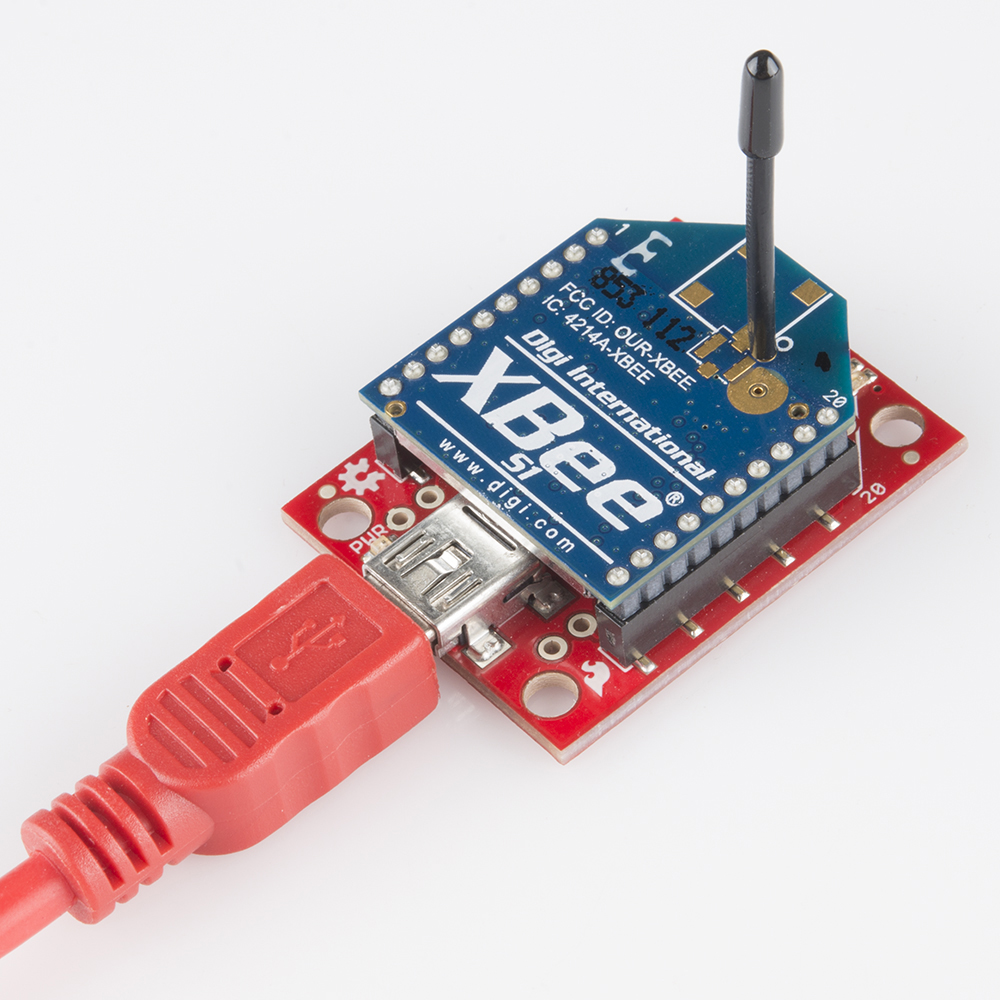
The focus of this tutorial is to explain how to use an XBee Explorer with an XBee. There are a variety of Explorer boards, all designed to
achieve the same purpose: to create a communication gateway between your computer and the XBee.
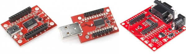
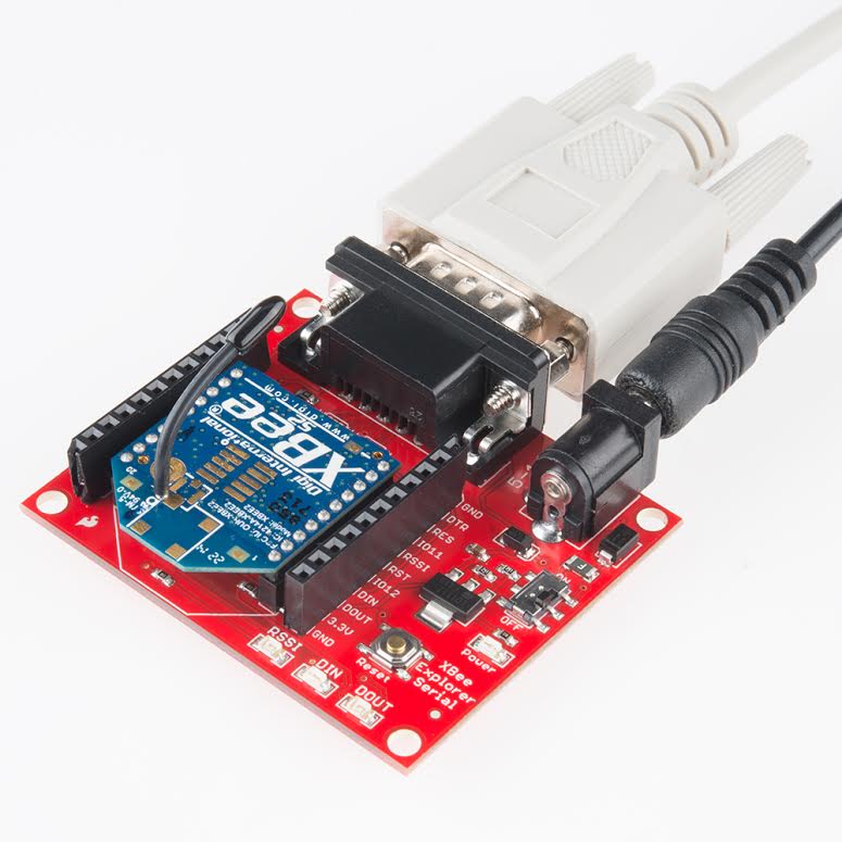
The Explorers: USB Explorer, Explorer Dongle, and Serial Explorer.
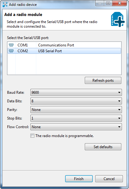
With an XBee Explorer connected between your computer and your XBee, and with the help of the X-CTU software, you can easily
configure XBees, test connections, and pass data between your computer and remote XBees. We're going to show you how to do all of
that in this tutorial!
Materials Required
XBees are really only useful if you have at least a pair of them. They need buddies to talk to! Hence, there's a lot of "2x" in this list of
materials. To follow along with this tutorial, you will need the following materials. You may not need everything though depending on what
you have. Add it to your cart, read through the guide, and adjust the cart as necessary.
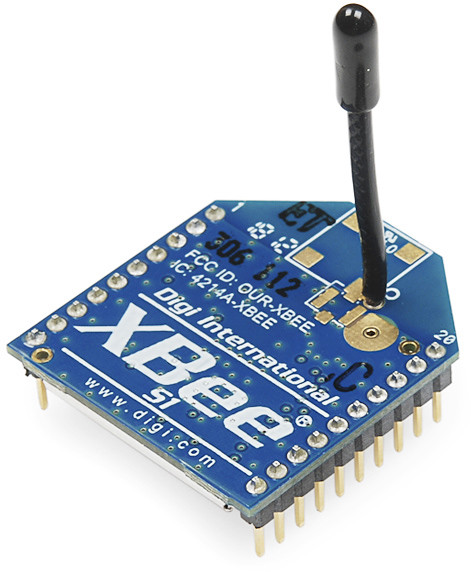
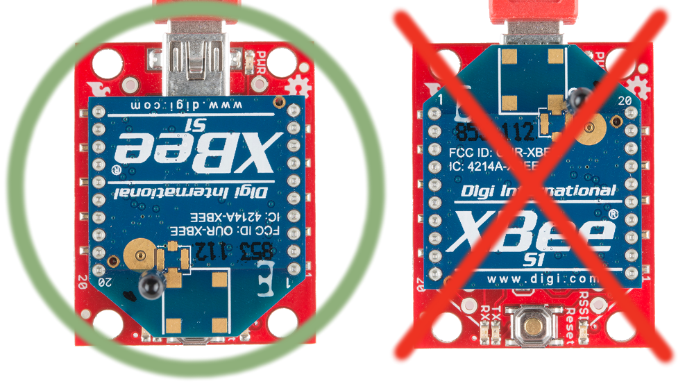
2x XBees -- XBees exist in a variety of series, frequencies, and ranges. If you're just getting started with XBee, we highly
recommend going with Series 1 (or Series 3 configured with the 802.15.4 protocol) models with a built-in antenna -- either with a
trace antenna, wire antenna. You can also get one with a u.fl connector but you will need to get the appropriate external antenna.
For more help picking an XBee, check out our XBee Buying Guide.
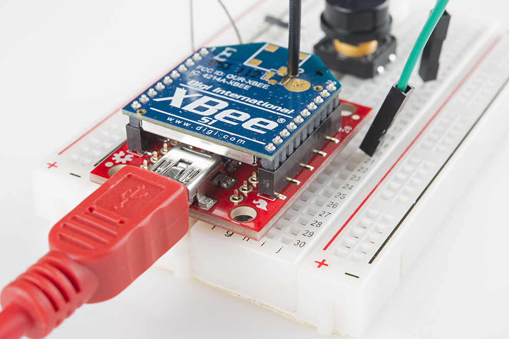
2x Explorers -- either the Explorer USB, Explorer USB Dongle, or Explorer Serial.
These boards act as an interface between your computer and an XBee. They're used to configure your XBee and pass data to
and from your computer.
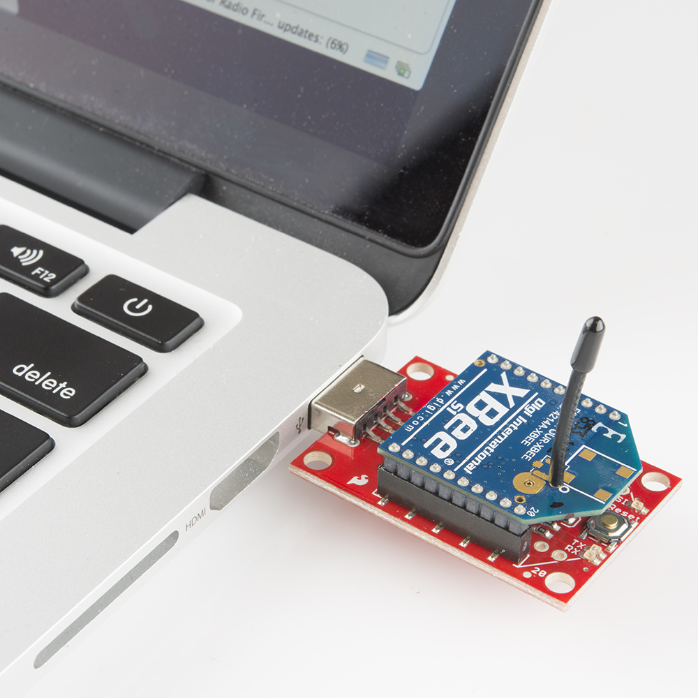
Depending on which explorer you have, you may also need a matching mini-B USB or serial cables.
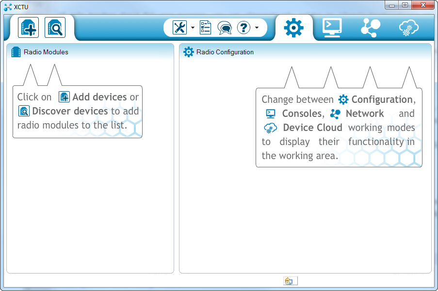
At least one computer with X-CTU installed.
The latest version of X-CTU is available for both Mac and Windows!
Suggested Reading
Don't know what XBees to start with? Try checking out our buying guide to compare the different modules.
XBee Buying Guide -- We highly recommend Series 1 XBee's, if this is your first time playing with them. If you're curious about other
XBee classes, check out this guide!
This tutorial builds on some lower-level electronics concepts. If you're not familiar with the subjects below, we recommend checking out
those tutorials first.
Serial Communication -- XBee's communicate over a serial port. This tutorial will get you familiar with terms like "RX", "TX", "baud
rates", "stop bits", and "parity".
Serial Terminal Basics -- The X-CTU software we'll use has an integrated serial terminal called the "console". You can use your
preferred terminal instead; if you don't have a preferred serial terminal, check out this tutorial.
How to Install FTDI Drivers -- If you are using an FTDI to connect to the XBees, you'll need to install the appropriate drivers.
Hexadecimal -- XBee configuration settings -- like addresses and network ID's -- are all programmed in hex. Base 16. If you don't
know how to make numbers with 0-9 and A-F, check out this tutorial.
Serial Communication
Asynchronous serial communication concepts: packets, signal levels, baud rates, UARTs and more!
Favorited Favorite 85
How to Install FTDI Drivers
How to install drivers for the FTDI Basic on Windows, Mac OS X, and Linux.
Favorited Favorite 8
Page 2 of 24
Serial Terminal Basics
This tutorial will show you how to communicate with your serial devices using a variety of terminal emulator applications.
Favorited Favorite 33
Hexadecimal
How to interpret hex numbers, and how to convert them to/from decimal and binary.
Favorited Favorite 25
Selecting an Explorer
Compatibility with XBee 3's Overall, SparkFun boards designed with the XBee footprint are hardware compatible with XBee Series 3
modules. They modules are drop-in replacements for Series 1 and Series 2 with a few exceptions. Below are two of those exceptions
taken out of the migration guide and hardware reference manual.
VREF - VREF (pin 14) on the XBee Series 1 is not supported by the XBee 3 hardware. As indicated in the hardware reference
manual, you should not connect to this pin on boards labeled with VREF.
Brownout - If your XBee 3 experiences any voltage brownouts or supply dips when powering up, your XBee may not start up as
expected. The hardware reference manual indicates that:
Parts with an early revision of the microcontroller unit (MCU) may experience an issue recovering from brownouts under
rare conditions.
To remedy the issue, you must power cycle the XBee Series 3 module. One method is to remove the XBee while the board is
powered. Then reinsert the module back carefully into the sockets. Otherwise, you can perform a hardware reset by toggling the
XBee 3's reset pin. To automate this, during startup, you can solder a wire between the reset pin and the 3.3V I/O pin of a
microcontroller Toggling the reset pin with a minimum of 50ns-100ns will reset the XBee Series 3. As an example, check out this
Arduino example code for the XBee Series 3 on the wireless joystick.
   
For more detailed information regarding the differences, check out the XBee 3 Documentation.
Migration Guide
Hardware Reference Manual
Special Considerations for XBee XSC Modules! For those using an XBee XSC series, the pinout is slightly different in the XBee family.
Pin 6 on the XBee XSC series uses it as a configuration pin (as stated on page 96 of the datasheet), instead of having an RSSI pin on pin
6 like most XBees. For standard serial UART pass-through uses, this module can be mounted to one of our XBee Explorer boards with a
small adjustment. For the explorer's, locate the RSSI jumper on the back, and cut the trace between the pads with a hobby knife. For the
XBee shield, simply disconnect the resistor or LED next to the RSSI pin using a soldering iron.
The first step to communicating with your XBee is picking an interface board that allows you to. XBee Explorers act as a gateway between
your computer and your XBee. There are a few to pick from, each offering their own, key differences. Here's a quick overview of each:
XBee Explorer USB
The XBee Explorer USB is the most popular of the Explorers. It's equipped with a mini-B USB connector, so you'll need the proper USB
cable to connect it to your computer.
Page 3 of 24
The highlight of this board is an FT231X USB-to-Serial converter. That's what translates data between your computer and the XBee.
There's also a reset button, and a voltage regulator to supply the XBee with plenty of power. In addition, there are four LEDs that'll help if
you ever need to debug your XBee: RX, TX, RSSI (signal-strength indicator), and a power indicator.
This board also breaks out each of the XBee's I/O pins to a pair of breadboard-compatible headers. So if you want to make use of the
XBee's extended functionality, you can solder some header pins into those, or even just solder some wire.
Hook-Up Wire - Assortment (Solid Core, 22 AWG)
PRT-11367
$16.95
32
Favorited Favorite 65
Wish List
Break Away Headers - Straight
PRT-00116
Page 4 of 24
$1.50
20
Favorited Favorite 111
Wish List
Female Headers
PRT-00115
$1.50
7
Favorited Favorite 57
Wish List
XBee Explorer USB Dongle
The XBee Explorer Dongle is an extension of the Explorer. In fact, the only real difference between this and its predecessor is the USB
connector. The Dongle can be connected directly to your laptop or PC USB port.
Or, if you need some distance from your computer, you can use a USB extension cable.
Page 5 of 24
USB Cable Extension - 6 Foot
CAB-00517
$3.95
Favorited Favorite 1
Wish List
The Dongle still shares all of the features of its sibling -- reset button, LEDs, voltage regulator, and breadboard-compatible pin breakouts.
XBee Explorer Serial
Computers with an RS-232 serial port are becoming harder and harder to find, but if you do have one of those relics, the XBee Explorer
Serial is a viable option.
The Serial Explorer has a bigger footprint than its USB-based brethren, but still shares most of the same features. There are RX and TX
LEDs, reset button, break-out pins, and a voltage regulator. One additional feature that the Serial Explorer has is an On/Off switch on
board. This enables the user to turn on or off the power supply to the XBee module.
One additional feature available on the Serial Explorer are two jumpers available near the DB9 connector. These allow the user to swap
the configuration of the DB9 connector to work with either a straight through cable (DCE configuration), or a switched cable (DTE
configuration). If you’re using our Serial Cable, the default DCE configuration of the jumpers is fine.
Page 6 of 24
Serial Cable DB9 M/F - 6 Foot
CAB-00065
$4.25
Favorited Favorite 4
Wish List
The Serial Explorer does require an external power supply. It has a barrel jack connector which will work with our 12V, 9V, or 5V wall
adapters. Make sure the selected power supply can source enough current for the XBee you are using.
Wall Adapter Power Supply - 9VDC 650mA
TOL-00298
12 Retired
Favorited Favorite 23
Wish List
Wall Adapter Power Supply - 12VDC 600mA
TOL-09442
13 Retired
Favorited Favorite 15
Wish List
Wall Adapter Power Supply - 5V DC 2A (Barrel Jack)
TOL-12889
16 Retired
Favorited Favorite 19
Wish List
Heads up! If you're using an Arduino, another option available is the XBee Shield. That's a subject for another tutorial. Let's focus on
Page 7 of 24
configuring a pair of XBees first.
XBee Shield Hookup Guide
June 5, 2014
How to get started with an XBee Shield and Explorer. Create a remote-control Arduino!
Favorited Favorite 10
Drivers and Assembly
The USB-based XBee Explorers all operate using an FTDI FT231X chip, which converts serial to USB and vice-versa. This is one of our
favorite chips because it supports all computer platforms and it's easy to work with. If this is the first FTDI chip you've ever connected to
your computer (it probably won't be your last), there is some driver installation to get out of the way.
We've written a tutorial detailing How to Install FTDI Drivers tutorial. So go ahead and plug your USB Explorer into your computer, and
head on to either the Windows, Mac, or Linux section there. (Ignore the final steps, where Arduino software is invoked.) Regardless of
whether you're on Mac or Windows, once your Explorer's drivers are installed it will be assigned a unique COM port number. Take note
of that port number, as you'll need it on the next pages.
How to Install FTDI Drivers
June 4, 2013
How to install drivers for the FTDI Basic on Windows, Mac OS X, and Linux.
Favorited Favorite 8
Basic Assembly: Plug In an XBee!
Time to "assemble" the XBee Explorer. Grab your XBee of choice. Notice how it has a flat edge and a more angular/diagonal edge?
Match that footprint up to the white lines on your XBee Explorer, and carefully insert! Take care not to bend any of the XBee pins -- be
gentle when you're plugging it in. (And be even more careful if you're removing it!)
Nice work! You've assembled the XBee Explorer. You're ready for the next step. Or, if you're a power user, looking to get the most out of
your explorer, you can check out the more "advanced" assembly below.
Advanced Assembly (Totally Optional)
For most basic-use cases, all Explorer boards should be good-to-go once you've installed drivers. If you want to use any of the XBee's I/O
pins, you can solder male headers to the 0.1"-pitch pins inside the XBee headers. This will allow you to plug the board into a breadboard,
so you can wire other components up to the XBee. Each XBee pin is labeled on the bottom side of the board. You can also check out the
schematic for help locating a specific pin.
Page 8 of 24
The XBee Explorer can be used with a USB cable and breadboard concurrently -- just solder some headers into the breakout pins.
(Actually solder them, don't pretend like we did in the image above.)
If male headers don't fit your purpose, you can alternatively solder in female headers (to plug jumper wires into), or even just bare wire.
Just make sure you don't solder anything into the top side of the board -- or you may be unable to plug the XBee in!
Tip: We won't cover it in this tutorial, but those "DIO#" pins can be configured as either inputs or outputs. That means you can use an
XBee to directly drive LEDs or motors, and read analog sensors or buttons. Just make sure to use a logic level converter or transistor
when using the pins for I/O line passing. More information about configuring the pins for I/O line passing can be found in the XBee's user
manual.
Starting With X-CTU
X-CTU is free software, provided by Digi (the manufacturer of XBee), which we use to configure and manage XBees, and test XBee
networks. If you haven't already, head over to their website and download the latest release and follow their instructions to install the
software.
Download X-CTU
Tip: The latest XBee Series 3 has enhanced features including new AT commands, Bluetooth, and MicroPython. While MicroPython is
available for the XBee Series 3, not all MicroPython modules are available for the XBee Series 3. For more information, make sure to
check the support documentation.
Adding XBee's
Before continuing on, make sure you've plugged an XBee (correctly) into your Explorer, and have the Explorer plugged into your
computer. When you installed the drivers for your Explorer it should have been assigned port number. You'll need that shortly.
After initially opening X-CTU, you'll be presented with a window like this:
Page 9 of 24
To add your XBee(s), click the "Add device" icon -- -- in the upper-left part of the window. That will prompt this screen to show
up:
Select Your Communication Port
If you're lucky (or just don't have a lot of stuff connected to your computer) you may only have one option here. Otherwise, Windows users
should look for the entry that says "USB Serial Port" and Mac users should look for something like "usbserial-XXXXXXXX", if you're using
a USB XBee board. If you're using a Serial Explorer instead, pick the "Communications Port" option. If the Serial Explorer is not showing
up, make sure the switch onboard is set to “On”!
This window also allows you to specify more specific serial characteristics like baud rate, data bits, and stop bits. Assuming this is the first
Page 10 of 24
time you've used your XBee, you can leave those settings alone. So make sure those values look just as they do in the image above
and click Finish.
A "Discovering radio modules..." window will briefly scroll by, after which you should be presented with the original window, but with an
addition to the "Radio Modules" section on the left. (If X-CTU failed to find a module, check out our troubleshooting page.)
Click that new module, and wait a few seconds as X-CTU reads the configuration settings of your XBee. You should then be presented
with the entire configuration of your XBee. The image below shows an XBee Series 1 connected to the XCTU.
As you can see by scrolling down the right half, there are a lot of configuration settings available. We'll get to some of those later. For
now, though, verify that the configurable settings visible in the screenshot above match those of your XBee:
Channel = C
PAN ID = 3332
DH = 0
DL = 0
MY = 0
If your are using the XBee Series 3, you will need to follow the next section to configure the firmware for the 802.15.4 protocol (a.k.a.
Series 1)!
Configuring XBee Series 3's to Legacy Series 1 Firmware
If you are working with an XBee Series 3, you will have a different configuration setting. To follow along in this tutorial, click on the update
firmware button. If you are using the XBee Series 1, simply move to the next step to configure the XBees.
Page 11 of 24
A window will pop up indicating the types of firmware available to flash. By default, it will be listed as the Digi XBee2 Zigbee 3.0 TH
function protocol. You can select the legacy XBee Series 1 or legacy XBee Series 2 firmware. For the scope of this tutorial, we will be
using the Digi XBee3 802.15.4 TH function set. You will then select the firmware version. In this case, it is 2002. When ready, click the
Update button.
Product Family = XB3-24
Function Set = Digi XBee3 802.15.4 TH
Firmware Version = 2002 (Newest)
A window will pop up indicating that the XCTU is updating firmware. This can take a couple of seconds.
Page 12 of 24
Once you are finished, you will be notified that the firmware was successfully flashed. Click OK to continue on.
Make sure to update the firmware on all the XBee nodes in your network with the same protocol. Otherwise, you will have issues sending
data throughout your network. At this point, connect the second XBee Series 3 to your computer and repeat the process explained above
to configure the firmware.
Do It Again
To test communication between your XBee's you'll need to connect your second XBee to a computer as well. That means doing the "Add
device" dance one more time if you have not already.
If you have another computer available, you can install X-CTU on that as well and perform the same set up. You can certainly perform this
test with both XBees connected to the same computer as well, just make sure you select the correct port number when you're adding the
second XBee.
If you add a second XBee to the same computer, a second entry will be added to the "Radio Modules" list. Selecting either of those
Page 13 of 24
entries will show the configuration settings for that, specific XBee.
Note that there are two XBees in the list on the left. The configuration values shown are for the highlighted XBee.
If you're ever unsure which XBee is which, try to match up the MAC numbers. These numbers are printed on a sticker on the bottom side
of your XBee, and they're also listed in XCTU. (It's listed as the "Serial Number" high and low, and is un-modifiable.)
Page 14 of 24
Each XBee has a unique MAC address,
printed on a sticker in the highlighted area.
As with the last module, make sure all settings are defaulted to the same values. That'll make the next step possible.
Channel = C
PAN ID = 3332
DH = 0
DL = 0
MY = 0
Quick and Easy Test
Click the "Switch to Consoles" icon -- -- in the upper-right part of the window. This will switch from the configuration tab to the
console. We can use the console to send characters to an XBee, which will route that character over-the-air to any other XBee it's
connected to.
If you have two XBees connected to your computer, you can switch between each radio's console by selecting the device on the left.
First, open a serial connection on each device by clicking the connect icon -- . The icon will change, and the border of the
console will turn green.
Next, click into the left half of the console, and type a letter or number. You should notice that character echoed in a blue font (the
hexadecimal digits on the right represent the ASCII value). Now click into the other XBee's console. As long as it was open, you should
see that same character, but red. Try typing a different character into the second XBee's console, and you should see it work the other
way.
Page 15 of 24
If that worked, then your XBees are configured to talk to each other! If not, check out the troubleshooting page.
That your XBees can talk to each other out of the box is no real surprise. They're all configured, by default, to be on the same network
with the same addresses. That might be OK, but what if your neighbor is running an XBee-based robot control network, while you're trying
to automate your house? Every time they try to roll a bot forward, your garage door might open! To be safe, you should configure your
XBees to operate on a unique network. Fortunately, that, and most other XBee settings are easy to change. On to the next page!
Configuring Networks
XBees can be configured with few different modes to transmit/receive signals. These include:
Transparent Mode
API Mode
I/O Line Passing
For simplicity, we will be using a pair of XBee Series 1 (or XBee Series 3 configured with the 802.15.4 protocol) set in transparent mode to
replace a wired serial UART connection.
Transparent Mode
As we've mentioned, XBees are awesome because they're highly -- and easily -- configurable. Most of the XBee configuration settings
come down to controlling which other XBees it can talk to. On this page, we'll show you how to configure three of the most important XBee
settings there are for a point-to-point communication:
PAN ID
MY Address
Destination Address
Channel (CH)
There are a few levels to XBee networks. First, there's the channel. This controls the frequency band that your XBee communicates over.
Most XBee's operate on the 2.4GHz 802.15.4 band, and the channel further calibrates the operating frequency within that band. You can
usually leave the channel setting alone, or at least make sure every XBee you want to have on the same network operates on the same
Page 16 of 24
channel.
PAN ID (ID)
The next level of an XBee network is the personal area network ID (PAN ID). The network ID is some hexadecimal value between 0 and
0xFFFF. XBees can only communicate with each other if they have the same network ID. There being 65536 possible ID's, there's a very
small chance that your neighbor will be operating on the same network (as long as you change it from the default!).
Addresss (MY, DH, DL)
Finally there are MY and destination addresses. Each XBee in a network should be assigned a 16-bit address (again between 0 and
0xFFFF), which is referred to as MY address, or the "source" address. Another setting, the destination address, determines which
source address an XBee can send data to. For one XBee to be able to send data to another, it must have the same destination address
as the other XBee's source.
For example, if XBee 1 has a MY address of 0x1234, and XBee 2 has an equivalent destination address of 0x1234, then XBee 2 can send
data to XBee 1. But if XBee 2 has a MY address of 0x5201, and XBee 1 has a destination address of 0x5200, then XBee 1 cannot send
data to XBee 2. In this case, only one-way communication is enabled between the two XBee's (only XBee 2 can send data to XBee 1).
We can use X-CTU to easily configure each of those settings. Here's how:
Radio Configuration
After the last page, you should already have at least one XBee connected to X-CTU. If you're still over in the console tab, click back over
to the Configuration tab -- . Take a peak at the very first handful of settings, and you should see some familiar acronyms: CH, ID,
DH, DL, and MY. Beside each of those blocks is a text box -- that's where we'll type in our new settings.
Network ID (ID)
Begin by coming up with a unique network ID number. Think of your favorite number between 0 and 65535, consult your friends and
neighbors to make sure your favorite isn't their favorite, then convert it to hexadecimal. Or if you don't want to put that much effort into it,
use a random value like 35FD.
Type your 16-bit network ID into the white text box next to PAN ID.
MY Address (MY)
Page 17 of 24
Your next job is to create addresses for each XBee in your network. These values should be unique to each XBee in a network. The MY
address can be any value between 0x0000 and 0xFFFF. Type this address into the text box next to "MY 16-bit Source Address".
If you only have two XBees, you can assign the first an MY address of 0, and the other an address of 1.
Note: Your XBee's can share the same MY address, they'll both receive the same data if it's broadcasted to that address.
Destination Address (DH & DL)
The destination address defines which XBee your source XBee is talking to. There are actually two values used to set the destination:
destination high (DH) and destination low (DL). You can use that pair of values in one of two ways to set your XBee's mate:
1. Leave DH set to 0, and set DL to the MY address of the receiving XBee.
2. Set DH to the Serial Number High (SH) and DL to the Serial Number Low (SL) of your destination XBee.
Either method works, but the former -- setting DH to 0 and DL to the destination's MY address -- is usually easier.
Here's an example for setting up the ID, DH, DL, and MY values for a pair of XBees:
Setting Acronym XBee Node1 XBee Node 2
Channel CH C C
PAN ID ID 35FD 35FD
Destination Address High DH 0 0
Destination Address Low DL 1 0
16-bit Source Address MY 0 1
Notice how the only real differences are the DL and MY values, which are flip-flopped on each XBee.
Write Changes
Once you've made your changes to the text field, click the brown pencil icon ( ) to write your changes. The property background
should turn from green to blue, indicating it has been written to a non-default value.
XBee 1's config tab after writing the changes.
Now, just like last time, you can try to send data from one XBee to the other via the console. As long as the addresses and PAN ID's
match up, you should have the same success as last time.
While it may seem like a lot of work to get right back to where you were, using a unique PAN ID and addressing scheme will make your
data transfer more secure and reliable.
Troubleshooting
If your XBee's are giving you any trouble, here are some common problems and fixes we recommend:
Page 18 of 24
Can't Find Device -- If XCTU can't find your XBee, we recommend recovery or discovery.
XBees Not Communicating Wirelessly -- If a pair of XBees are failing to communicate, we recommend resetting everything to
default.
Resetting XBees -- A trick to resetting your XBee (if you don't have a reset button).
Can't Find Device
Are you having a hard time "finding" an XBee? If you're "Add Device" process is being followed by a window like this:
There are two options we recommend: discovery or recovery.
Discovery
The Discover radio devices tool is an extension of "Add devices". Open the discovery window by clicking the XBee/magnifying glass
icon -- -- in the top-left.
Once again you'll be prompted to select which communication port your XBee is connected to. Double check that you've selected the
correct one (or even try multiple). The next window will present you with every, single serial setting available, and a whole lot of
checkboxes:
Page 19 of 24
Most of the cases where your XBee is hiding it's because the baud rate has been altered. A quick fix for this is to select all possible
baud rates in the discovery window, then click Finish. The discovery process works a lot like the add process except it tests out every
selection you make in this window -- that means it will take a little longer to finish.
Hopefully you've found an XBee that was just configured to talk at a weird baud rate. If not you can select any of the other checkboxes as
well, but it'll make for a longer and longer discovery process. Click every checkbox and you might be waiting upwards of an hour for your
XBee to be discovered (permutations!).
If you're not having any luck with discovery, the next step is recovery.
Recovery
If your XBee seems bricked, don't worry! You can most likely recover it. To get to the recovery screen, click the Tools icon, and select
XBee Recovery.
Once again, you'll need to select your COM port, and you'll also need to select the product family. This can be found on the bottom sticker
of your XBee. If you're using a series 1 module, the family should be XB24. Beyond that you'll need to select a "Function Set" and
"Firmware Version". For both of those you should be safe selecting the top-most values in the list.
Page 20 of 24

Other XBee Control Unit manuals

XBee ZNet 2 Series Installation and user guide

XBee

XBee ZNet 2 Series Installation and user guide

Popular Control Unit manuals by other brands

Aion Electronics Nebula DS-830 Distortion Master quick start guide

Aion Electronics

Aion Electronics Nebula DS-830 Distortion Master quick start guide

Kontron COMe-bSL6 user guide

Kontron

Kontron COMe-bSL6 user guide

Advantech PCM-3614I Startup manual

Advantech

Advantech PCM-3614I Startup manual

clare ClareOne 16 Zone Hardwired Input Module manual

clare

clare ClareOne 16 Zone Hardwired Input Module manual

Sparkfun Electronics AD8232 HOOK-UP GUIDE

Sparkfun Electronics

Sparkfun Electronics AD8232 HOOK-UP GUIDE

schmersal AES 9107 operating instructions

schmersal

schmersal AES 9107 operating instructions

Bernini Be42 manual

Bernini

Bernini Be42 manual

Burkert 3360 Service manual

Burkert

Burkert 3360 Service manual

WABCO MICO ACV-DMO-RV Product Explanation, Operating Information, and Service Instructions

WABCO

WABCO MICO ACV-DMO-RV Product Explanation, Operating Information, and Service Instructions

Phoenix Mecano DewertOkin MC10 installation instructions

Phoenix Mecano

Phoenix Mecano DewertOkin MC10 installation instructions

Lenze ECSDS Series Mounting instructions

Lenze

Lenze ECSDS Series Mounting instructions

Bardiani BBZS1 Instruction, use and maintenance manual

Bardiani

Bardiani BBZS1 Instruction, use and maintenance manual

ICP DAS USA M-7041 quick start guide

ICP DAS USA

ICP DAS USA M-7041 quick start guide

GEM 8257 Installation, operating and maintenance instructions

GEM

GEM 8257 Installation, operating and maintenance instructions

Allen-Bradley ArmorPoint A Series installation instructions

Allen-Bradley

Allen-Bradley ArmorPoint A Series installation instructions

CALEFFI 535H Series Installation, commissioning and servicing instructions

CALEFFI

CALEFFI 535H Series Installation, commissioning and servicing instructions

Pentair Fleck 5800 XTR Installer manual

Pentair

Pentair Fleck 5800 XTR Installer manual

PR 9410 manual

PR

PR 9410 manual

manuals.online logo
manuals.online logoBrands
  • About & Mission
  • Contact us
  • Privacy Policy
  • Terms and Conditions

Copyright 2025 Manuals.Online. All Rights Reserved.