Abilica 555 200 User manual

--
1
Assembly Instructions
Infinity 2-Station Home Gym
Art No. 555 200 &
OPTION:Dip Station (VKR)
Art No. 555 210

--
1
IMPORTANT SAFETY
INFORMATION
TO AVOID INJURY AND/OR AN ACCIDENT READ AND
FOLLOW THESE SIMPLE SAFETY RULES:
1. Do not allow children to play on or around UNIT.
2. Securely tighten all nuts and bolts and regularly check to insure that all bolts and
nuts have not loosened.
3. With use normal wear of components can be expected. Therefore, periodic
inspection of moving components should be performed. Pay particular attention to
areas of metal to metal contact such as quick-links and replace when noticeable
wear occurs.
4. Do not try to remove weight selector rod while UNIT is in use.
5. Keep your hands away from path of cables, and weight stacks when UNIT is in use.
6. Be certain that pull pins and rods are fully inserted and quick-links are completely
closed before using UNIT.
7. Do not wear loose robes, gowns, pants, long skirts, or jewelry such as necklaces,
chains, rings, etc., which may become entangled in moving parts.
8. Do not stand or kneel on seats.
9. Wear only a rubber sole shoe. Hard sole or spiked heel shoes may cause you to
slip and fall.
CAUTION
BEFORE STARTING ANY EXERCISE PROGRAM, IT IS RECOMMENED
THAT YOU CONSULT YOUR PHYSICIAN.

--
2
ITEM NUMBERS IN INSTRUCTIONS ARE SAME AS ITEM NUMBERS IN PARTS LIST.
THE HARDWARE QUANTITIES SHOWN IN PARTS LIST, ARE QUANTITIES REQUIRED TO
COMPLETE ASSEMBY OF THIS PRODUCT. IF YOU FIND YOU HAVE MORE HARDWARE
THAN IS REQUIRED, DISCARD EXCESS HARDWARE.
INCHES
MILLIMETERS
PLACE WASHER, END OF BOLT, OR SCREW
ON CIRCLE TO CHECK FOR CORRECT SIZE.
HARDWARE ILLUSTRATIONS
HEX HEAD BOLT
SOCKET HEAD SCREW
LOCKNUT
FLAT WASHER
ROUND PLUG
SQUARE PLUG
NOTE : The hardware may vary (type of head or length) from what is specified, but the
variation in no way will affect the product’s quality.

--
3
PARTS LIST
ITEM
PART NO.
Q’TY
PART NAME
1
02059100
8
Cap
2
38402316
1
Front Floor Tube
3
38402416
1
Dip Stand Base
4
38402616
1
Base
5
31308716
2
Flat Plate
6
22035300
22
M10 × 1.5 × 75 mm Long Hex Head Bolt
7
26016800
81
M10 Washer
8
25028300
40
M10 × 1.5 Locknut
9
30489716
1
Rear Floor Tube
10
02054400
13
2” Square Plug
11
02056500
2
1 1/2” Square Plug
12
38402716
1
Rear Support
13
39442000
2
Arm Assembly
14
39441500
1
Front Support Assemble
14a
38402916
1
Front Support
14b
09153200
1
Bumper
14c
21030100
1
M6 × 1 × 16mm Long Machine Screw
14d
26023100
1
M6 Washer
15
38403216
1
Top Support
16
31308616
5
Channel Plate
17
34441400
1
Butterfly Mount (Assembly)
17a
38402516
1
Butterfly Mount
17b
09190100
2
Pad
18
38403016
1
Rear Seat Mount
19
39443100
2
Seat Pull Knob
20
09153700
2
Weight Bumper
21
30447167
2
Guide Rod
22
39345700
19
Weight
23
31284967
1
Weight Selector Rod
24
31283016
1
Plate
25
22023500
1
7/16” × 1 1/2” Long Socket Screw
26
29431000
1
Pull pin
27
09153500
1
Cover
28
38403316
1
Dip Stand Support
29
38403416
1
Guide rod Support
30
38333067
3
Handle
31
22035500
5
M10 × 1.5 × 20mm Long Hex Head Bolt
32
02059000
9
Small Grip
33
62416300
1
Weight Label (set)
34
38403516
1
Dip Stand
35
39441900
1
Dip Stand Backrest
36
22024000
2
M8 × 1.25 × 20mm Long Hex Head Bolt
37
26011400
24
5/16” Washer
38
22025400
12
M8 × 1.25 × 60mm Long Hex Head Bolt
39
02058800
2
End Cap
40
02058900
2
Large Grip
41
30483116
1
Rear Seat Support
42
39442200
1
Rear Seat
43
39443400
2
Locking Knob
44
39442100
2
Back Cushion

--
4
ITEM
PART NO.
Q’TY
PART NAME
45
38403616
1
Front Seat Mount
46
29461000
1
Lift Tube
47
39461000
6
“D” Bushing
48
22035400
1
M12 × 1.75 × 80mm Long Hex Head Bolt
49
26023300
10
M12 Washer
50
25028400
7
M12 Locknut
51
38403716
1
Front Seat Support
52
39442300
1
Front Seat
53
02053100
6
Round Plug
54
30447067
3
Sleeve Tube
55
04039700
6
Short Sleeve
56
02029300
6
Rectangle Plug
57
38404016
1
Handlebar Support
58
29460300
6
Bronze Bushing
59
29471200
1
Axle
60
22035700
4
M8 × 1.25 × 15mm Long Hex Head Bolt
61
38404416
1
Right Swivel Bracket
62
38404516
1
Left Swivel Bracket
63
22035800
2
M12 × 1.75 × 100mm Long Hex Head Bolt
64
38404316
2
Butterfly Arm
65
38404116
1
Right Pivot Arm
66
38404216
1
Left Pivot Arm
67
22035600
2
M12× 157mm Long Hex Head Bolt
68
61195700
1
Assembly Instructions
69
39443300
2
Butterfly Pull Knob
70
04045300
2
Long Sleeve
71
29460600
1
Lockout Pin
72
29471500
1
Lower Cable
73
29471400
1
Upper Cable
74
29471300
1
Butterfly Cable
75
39437200
16
Pulley
76
22036000
1
M10 × 1.5 × 65mm Long Hex Head Bolt
77
22035900
13
M10 × 1.5 × 50mm Long Hex Head Bolt
78
31302116
2
Pulley Plate
79
29469500
4
Snap-Link
80
29461100
1
Short Chain
81
38404616
1
Pulley Bracket
82
22036100
2
M10 × 1.5 × 120mm Hex Head Bolt
83
09201800
4
Small Spacer
84
38403916
1
Handlebar
85
31308867
1
Pivot Tube
86
26023400
2
M8 Washer
87
09201900
2
Large Spacer
88
39443200
1
Handlebar Pull Knob
89
38381767
1
Lat Bar
90
38404867
1
Curl Bar
91
29479167
1
Long Chain
92
39345500
1
Pull Handle
93
13049600
1
Ankle Strap
94
60129500
1
Usage Manual
95
09190100
2
Rubber Pad
96
04029501
2
Pad

--
5
IMPORTANT
PLEASE READ ASSEMBLY INSTRUCTIONS CAREFULLY BEFORE ASSEMBLING.
FIGURE 1
Step 1. Push CAPS (1) over ends of FRONT FLOOR TUBE (2), DIP STAND BASE (3) and BASE
(4). (It is option:Dip Stand Step)
Step 2. Attach FRONT FLOOR TUBE (2), with BRACKET to front side, to LONG END of BASE (4),
with BRACKETS facing up, using FLAT PLATE (5), BOLTS (6), WASHERS (7) and
LOCKNUTS (8).
Step 3. Attach DIP STAND BASE (3) to BASE (4) with BOLTS (6), WASHERS (7) and LOCKNUTS
(8).

--
6
FIGURE 2
Step 4. Push CAPS (1) over ends of
REAR FLOOR TUBE (9).
Step 5. Push 2” SQUARE PLUG (10)
into REAR SUPPORT (12).
Step 6. Push 1 1/2” SQUARE PLUGS
(11) into REAR SUPPORT
(12).
Step 7. Attach REAR FLOOR TUBE
(9) and REAR SUPPORT (12)
to BASE (4) with BOLTS (6),
WASHERS (7) and
LOCKNUTS (8).
Step 8. Attach FRONT SUPPORT (14),
with STOP TUBE facing
FRONT, to BASE (4) with BOLT
(6), WASHERS (7) and
LOCKNUT (8).

--
7
FIGURE 3
Step 9. Push 2” SQUARE PLUG (10) into TOP SUPPORT (15).
Step 10. Attach TOP SUPPORT (15), with BRACKETS facing down, to FRONT SUPPORT (14)
using BOLTS (6), CHANNEL PLATE (16), WASHERS (7) and LOCKNUTS (8).
Step 11. Attach TOP SUPPORT (15) to REAR SUPPORT (12), through TOP HOLES, with BOLTS
(6), CHANNEL PLATE (16), WASHERS (7) and LOCKNUTS (8).
Step 12. Attach BUTTERFLY MOUNT (17) to REAR SUPPORT (12) with BOLTS (6), FLAT PLATE
(5), WASHERS (7) and LOCKNUTS (8). Press RUBBER PADS (95) into holes on
backside of BUTTERFLY MOUNT.

--
8
FIGURE 4
Step 13. Attach REAR SEAT MOUNT (18), to one of three mounting positions, on REAR SUPPORT
(12) with BOLTS (6), CHANNEL PLATE (16), WASHERS (7) and LOCKNUTS (8).
Step 14. Thread SEAT PULL KNOB (19) into REAR SEAT MOUNT (18).
Step 15. Slide WEIGHT BUMPERS (20) onto GUIDE RODS (21) and insert GUIDE RODS into
GUIDE ROD HOLES in BASE (4).
NOTICE
There are three short PULL KNOBS
and two long PULL KNOBS. The
HANDLEBAR PULL KNOB (88) is one
of the short PULL KNOBS but has
more threads than the other two. The
SEAT PULLKNOB (19) is the other two
short PULL KNOBS. The two long
PULL KNOBS are the BUTTERFLY
PULL KNOBS (69).

--
9
FIGURE 5
Step 16. Carefully slide WEIGHTS (22), one at a time with GROOVE on bottom and facing outside,
down GUIDE RODS (21).
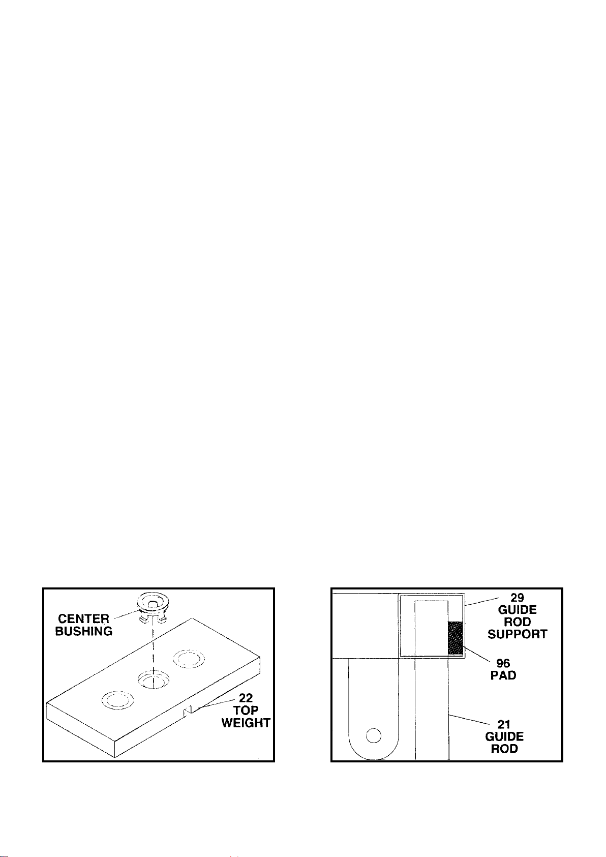
NOTE: Remove CENTER BUSHING from TOP WEIGHT –see DETAIL “A” below.
Step 17. Insert WEIGHT SELECTOR ROD (23) into CENTER HOLE of PLATE (24) and fasten, at
TOP HOLE, with SOCKET SCREW (25).
Step 18. Slide PLATE (24) down GUIDE RODS (21), with SOCKET SCREW (25) facing outside,
and insert PULLPIN (26) through GROOVE in BOTTOM WEIGHT (22) and BOTTOM
HOLE of WEIGHT SELECTOR ROD (23).
Step 19. Slide COVER (27) down GUIDE RODS (21), with HOLE facing outside, and over PLATE
(24) until SOCKET SCREW (25) locks into HOLE in COVER.
Step 20. Attach DIP STANT SUPPORT (28) to DIP STAND BASE (3) with BOLT (6), WASHERS (7)
and LOCKNUT (8).
Step 21A. Push a PAD (96) into each side of GUIDE ROD SUPPORT (29), between GUIDE RODS
(21) and wall of GUIDE ROD SUPPORT –see DETAIL “B”.
Step 21B. Push 2” SQUARE PLUGS (10) into GUIDE ROD SUPPORT (29).
Step 22. Slide GUIDE ROD SUPPORT (29) onto GUIDE RODS (21).
Step 23. Attach GUIDE ROD SUPPORT (29) and DIP STAND SUPPORT (28) to TOP SUPPORT
(15) with BOLTS (6), WASHERS (7) and LOCKNUTS (8).
Step 24. Insert HANDLE (30) into DIP STAND SUPPORT (28) and fasten with BOLT (31) and
WASHER (7).
Step 25. Push SMALL GRIP (32) onto HANDLE (30).
Step 26. Apply WEIGHT LABELS (33) to WEIGHTS (22) as follows:
20lb. LABEL to TOP WEIGHT.
(WEIGHT SELECTOR ROD (23) and PLATE (24) weigh 10lbs.)
Continue applying WEIGHT LABELS until 2001b. LABEL is applied
DETAIL “A”
DETAIL “B”

--
10
FIGURE 5

--
11
FIGURE 6
(Step 27-32 :It is option:Dip Stand Step)
Step 27. Attach DIP STAND (34), with LONG END facing down, to DIP STAND SUPPORT (28) with
BOLTS (6), CHANNEL PLATE (16), WASHERS (7) and LOCKNUTS (8). Step 28. Attach
DIP STAND BACKREST (35) to DIP STAND (34) with BOLTS (60) and WASHERS (37).
Step 29. Attach ARM CUSHIONS (13) to DIP STAND (34) with BOLTS (38) and
WASHERS (37).
Step 30. Push END CAPS (39) and LARGE GRIPS (40) onto DIP STAND (34).
Step 31. Insert HANDLES (30) into DIP STAND (34) and fasten with BOLTS (31) and WASHERS
(7).
Step 32. Push SMALL GRIPS (32) onto HANDLES (30).
(Step 27-32 :It is option:Dip Stand Step)

--
12
FIGURE 7
Step 33. Push 2” SQUARE PLUGS (10) into ends of REAR SEAT SUPPORT (41) as shown.
Step 34. Attach REAR SEAT(42) to REARSEATSUPPORT (41) with BOLTS (38) and WASHERS (37).
Step 35. Pull SEAT PULL KNOB (19) and insert REAR SEAT SUPPORT (41), with SMALL END of
REAR SEAT (42) facing REAR, into REAR SEAT MOUNT (18) and release SEAT PULL
KNOB to lock REAR SEAT SUPPORT at desired height.
Step 36. Thread LOCKING KNOB (43) into REAR SEAT MOUNT (18) and tighten.
NOTE : Always tighten LOCKING KNOB before each use.
Step 37. Attach BACK CUSHION (44) to REAR SUPPORT (12) using BOLTS (38)AND washers (37).

--
13
FIGURE 8
Step 38. Thread a SEAT PULL KNOB (19) into GUIDE TUBE of FRONT SEAT MOUNT (45).
Step 39. Attach FRONT SEAT MOUNT (45) to FRONT SUPPORT (14), with 2” SQUARE PLUG (10)
facing up, using CHANNEL PLATE (16), BOLT (6), WASHERS (7) and LOCKNUTS (8).
Step 40. Push 2” SQUARE PLUGS (10) into FRONT SEAT MOUNT (45) and LIFT TUBE (46).
Step 41. Push “D” BUSHINGS (47) (see DETAIL “A”) into LIFT TUBE (46) and attach LIFT TUBE,
with GUIDE WIRE to FRONT, to BRACKET of FRONT SEAT MOUNT (45) using BOLT
(48), WASHERS (49) and LOCKNUT (50).
NOTE : DO NOT over tighten LOCKNUT. LIFT TUBE must pivot freely.
“D” BUSHING has a
FLAT SIDE as shown.
DETAIL “C”

--
14
FIGURE 9
Step 42. Push 2” SQUARE PLUGS (10) into FRONT SEAT SUPPORT (51).
Step 43. Attach FRONT SEAT (52) to FRONT SEAT SUPPORT (51), so that SMALL END will be
facing FRONT, with BOLTS (38) and WASHERS (37),
Step 44. Pull SEAT PULL KNOB (19) and insert FRONT SEAT SUPPORT (51), with SMALL END of
FRONT SEAT (52) facing FRONT, into GUIDE TUBE of FRONT SEAT MOUNT (45) and
release SEAT PULL KNOB for lock FRONT SEAT SUPPORT at desired height.
Step 45. Thread LOCKING KNOB (43) into GUIDE TUBE of FRONT SEAT MOUNT (45) and tighten.
NOTE : Always tighten LOCKING KNOB before each use.
Step 46. Attach BACK CUSHION(44)to FRONTSUPPORT (14) with BOLTS (38) andWASHERS (37).

--
15
FIGURE 10
Step 47. Push ROUND PLUGS (53) into each end of SLEEVE TUBES (54).
Step 48. NOTE: Spray window cleaner applied to inside of SHORT SLEEVES (55) and outside of
SLEEVE TUBES (54) will help SHORT SLEEVES slide on easier.
Push one SHORT SLEEVE onto one end only of each SLEEVE TUBE until flush with end
of SLEEVE TUBE.
Step 49. Slide SLEEVE TUBES (54) through LIFT TUBE (46) and LOWER or UPPER LOCATION in
FRONT SEAT MOUNT (45).
Step 50. Slide other SHORT SLEEVES (55) onto other end of SLEEVE TUBES (54).

--
16
FIGURE 11
Step 51. Push Rectangle Plugs (56) into HANDLEBAR SUPPORT (57).
Step 52. Push BRONZE BUSHINGS (58) into TOP SUPPORT (15) and HANDLEBAR SUPPORT (57).
Step 53. Thread LOCKNUT (50) onto AXLE (59) until tight.
Step 54. Insert AXLE (59) through BRONZE BUSHINGS (58) in HANDLEBAR SUPPORT (57) and
TOP SUPPORT (15) and fasten with LOCKNUT (50).
NOTE : Adjustment plate must be on right side as shown.
Step 55. Thread BOLT (60) into top of TOP SUPPORT (15) to lock AXLE (59) in place.
NOTE : DO NOT over tighten BOLT. It needs just enough pressure to keep the AXLE
from turning when in use.

--
17
FIGURE 12
Step 56. Attach SWIVEL BRACKETS (61 RIGHT & 62 LEFT ), with TOP of SWIVEL BRACKET
leaning to outside as shown in DETAIL “B” to each side of REAR SUPPORT (12) using
BOLTS (63), WASHERS (49) and LOCKNUTS (50).
Step 57. Push 2” SQUARE PLUGS (10) into each end of PIVOT ARMS (56 RIGHT & 66 LEFT).
Step 58 Push BRONZE BUSHINGS (47) into PIVOTARMS (65 & 66).
Step 59 Attach PIVOT ARMS (65 & 66) and BUTTERFLY ARMS (64) to BUTTERFLY MOUNT (17)
with BOLTS (67), WASHERS (49) and LOCKNUTS (50).
NOTE: DO NOT over tighten LOCKNUTS. Lubricate FLANGE of “D” BUSHING (47) with
machine oil or other household lubricant.
Step 60. Thread BUTTERFLY PULL KNOBS (69) into PIVOTARMS (65& 66) until tight.
Step 61. Pull BUTTERFLY PULL KNOBS (69) adjust BUTTERFLY ARMS (64) to desired position
and release BUTTERFLY PULL KNOBS to lock in place.
Step 62 NOTE: Spray window cleaner applied to BUTTERFLY ARMS (64), and inside LONG
SLEEVES (70) will help LONG SLEEVES slide on easier.
Slide LONG SLEEVES onto BUTTERFLYLARMS until flush with end.
TOP
LEANING
TO OUTSIDE
62
LEFT
SWIVEL
BRACKET
TOP
LEANING
TO OUTSIDE
61
RIGHT
SWIVEL
BRACKET
DETAIL “D”
FIGURE 12

--
18

--
19
FIGURE 13
Step 63. NOTE: See USAGE MANUAL (94) for specific exercises that require LIFT TUBE (46) to be
locked.
Insert LOCKOUT PIN (71) completely through both sides of BRACKET of FRONT SEAT
MOUNT (45) to lock LIFT TUBE.
Step 64. NOTE: There are three CABLES –see DETAIL “E” below. The LOWER CABLE (72) has
a BALL on one end an EYE on the other. The UPPER CABLE (73) has a BALL on one
end a threaded SCREW on the other. The BUTTERFLY CABLE (74) has EYES at both
ends.
Insert EYE end of LOWER CABLE (72) through GUIDE WIRE and LIFT TUBE (46) then
through SLOT in FRONT SUPPORT (14).
Step 65. NOTE: PULLEY COVERS are all the same. The PULLEY COVERS are designed so that
CABLES will ride in SLOTS and keep CABLE locked onto PULLEYS (75).
Place LOWER CABLE (72) in GROOVE of PULLEY (75) and place PULLEY COVERS on
each side so that LOWER CABLE is locked in SLOT of each PULLEY COVER and PIVOT
TUBE in PULLEY locks in HOLES of PULLEY COVERS.
IMPORTANT
ALL PULLEY and PULLEY COVERS are to be assembled in this manner.
Step 66. Place PULLEY (75), LOWER CABLE (72) and PULLEY COVER ASSEMBLY into LIFT
TUBE (46) and fasten with BOLT (76), WASHERS (7) and LOCKNUT (8).
Step 67. Assemble PULLEY (75), LOWER CABLE (72) and PULLEY COVERS and attach to
FRONT, CENTER and REAR PULLEY MOUNTS with BOLTS (77), WASHERS (7) and
LOCKNUTS (8).
Step 68. Make a PULLEY (75), LOWER CABLE (72) and PULLEY COVER ASSEMBLY between
CENTER and REAR PULLEY MOUNT. Attach ASSEMBLY together with PULLEY
PLATES (78) using BOLT (77), WASHERS (7) and LOCKNUT (8).
Step 69 Attach SNAP-LINK (79) to both ends of SHORT CHAIN (80).
Step 70 Attach SNAP-LINK (79) at one end of SHORT CHAIN (80) to EYE end of LOWER CABLE
(72) and the other end to PULLEY BRACKET (81).
72
LOWER CABLE
73
UPPER CABLE
74
BUTTERFLY CABLE
DETAIL “E”
This manual suits for next models
1
Table of contents
Other Abilica Home Gym manuals