Abilize Pursuit User manual

Abilize
•
匣(€

01
Table of Content
Introduction ------------------------------------------------2
Important Precautions -----------------------------------3
Safety Warning & Instruction Labels ----------------4
Identification of Parts ------------------------------------5
Installation Procedure -----------------------------------8
Charging the Batteries --------------------------------13
Regular Maintenance and Care ---------------------14
Safety Information on Electromagnetic
Interference (EMI) --------------------------------------14
Warranty --------------------------------------------------16
Trouble Shooting ---------------------------------------17
Care and Maintenance --------------------------------18
Specifications --------------------------------------------19

Thank you and congratulations on purchasing your new Abilize Mobility Powerchair.
It is designed to provide you with transportation ability indoors and outdoors.
We pride ourselves on providing safe and comfortable products. Our goal is to ensure your
complete satisfaction. We sincerely hope you enjoy your Abilize Mobility Powerchair.
Please read and observe all warnings and instructions provided in owner’s manual before
you operate the various functions of this Powerchair. Also, please retain this booklet for
future reference.
IF YOU HAVE ANY QUESTIONS, YOU CAN CONTACT:
UK Authorised Dealer
CareCo UK Ltd
Hubert Road
Brentwood
Essex
CM14 4JE
Tel: (+44) 01277 237001
Email: [email protected]
Information of European Representation
EMERGO EUROPE
Prinsessegracht 20
2514 AP, The Hague
The Netherlands
02

03
IMPORTANT PRECAUTIONS
Safety is the main consideration when using your chair. It is required that you read and
understand all the operating and safety instructions discussed in this manual, and ensure your
chair is correctly tted and adjusted by your dealer or the prescribing healthcare professional.
Make sure to engage the wheel locks before entering or leaving the chair. The wheel locks are
designed to prevent movement of the chair. It is preferable to ensure the front castors are in the
forward position before transferring into or out of the chair. With the castors in the forward position
the wheel base of the chair is increased and therefore, offers more stability.
DO NOT move forward in the seat while leaning forward out of the chair. If you need to pick an
object up from the oor, drive past it, then reverse so the front castors are in the forward position.
This gives the chair its greater stability.
To maintain lateral stability do not reach further than the length of your arm. DO NOT lean out of
the chair as this will cause instability.
When transferring, DO NOT stand on the leg rests. Depending on the style of leg rests either
swing them away or fold them up before transferring.
When approaching a ramp, be sure of your own ability and your limitations in terms of strength
and endurance.
Before attempting a ramp the following basic rules should be considered:
1. Surface of the ramp: Is it slippery?
2. Degree of incline: Is it too steep to attempt alone?
3. Length of ramp: Is it too long for your endurance?
4. Obstacles: Are there any obstacles on the ramp that would necessitate assistance?
Be very careful when going up or down steep inclines:
If it becomes necessary to stop when going up an incline, special care must be taken to avoid
abrupt or sudden forward movement. During continuous forward movements, the chair is capable
of falling backwards.
Always keep the chair under control when going down a ramp or incline. Speed should be
controlled at all times.
If you encounter a kerb whilst driving, caution should be taken to prevent the user being
thrown forward:
CAUTION: Do not try to climb a kerb by driving up it. Have a helper move the chair for you
following the instructions below.
Lifting the rear wheels rst if going down a kerb, or the front wheels rst if going up, ensure both
sides are lifted equally, and ensure the motors are disengaged.
CAUTION: Please be aware that any adjustments on the power chair may affect the
handling and performance.

1.Please read the instruction Booklet carefully before using your scooter.
2.Keep the scooter properly maintained.
3.Do not drive the scooter on slippery surfaces or on slopes over 8°
4.Do not drive on highways, crowded roads, or unfamiliar areas.
5.Do not tum at high speed in either forward or reverse.
6.Do not wash with water or leave scooter in a humid Environment since
water can damage the electric parts.
7.Always re-engage the emergency freewheel drive after use.
1
1
43
2
5 6
2
3
6
5
4
Wiring diagram label
Transaxle test ok label
Left N-D Lever adjustment label which instructs freewheel mode operation.
Right N-D Lever adjustment label which instructs freewheel mode operation.
Warning Sticker
1.Please read the instruction booklet carefully before using your scooter.
2.Do not drive the scooter on slippery surfaces or on slopes over 8 degrees limit.
3.Do not drive on highway, crowded roads, or unfamiliar areas.
4.Do not turn at high speed in either forward or reverse.
5.Do no wash with water or leave scooter in humid environment since water
can damage the electronic parts.
Serial Number
Model Number
Date of Manufacture
Manufacturer
Warning
WEEE Conformity
EU Authorized representative
Medical Device
European Conformity
Consult Instructions for Use
Maximum weight capacity
04

Before attempting to drive this power chair on your own, it is important that you familiarize
yourself with the controls and how they operate.
Figure 1 - Front View
Figure 2 - Control Panel / Joystick Figure 3 - Back View
Folding Backrest
Adjustable Height
Armrest
Anti -Tipper
Front Castor
Drive Train
Rear Wheel
Joystick Control
Skirt Guard
Footrest
Self Diagnostic Warning
Lights & Battery Gauge
Speed Control
Button
Horn
Direction
Control
Knob
Anti-Tip
Wheels
Support
Brace
Free-Wheel
Lever
05

IDENTIFICATION OF PARTS
Footrest Height Adjustment:
1. Remove both side’s height xation screws (A). (See Fig. 4)
2. Adjust to required position.
3. Aim for the required hole’s position to tighten height xation screw.
CAUTION: Careful not to interfere with front wheel when adjusting.
Seat Belt Usage:
1. Prior to driving fasten the seat belt as the picture illustrates (B) (B1).
2. Seat Belt can be unfastened by pressing down the red button (B2).
Free Wheel Levers:
1. For your convenience, the chair is equipped with two free wheel levers.
These levers allow you to disengage the drive motors and manoeuvre
the chair manually if you need to stop or encounter a problem.
2. When travelling, set the two metallic levers (C) to the drive position.
(See Fig. 5)
3. The battery box with plug goes in the front position. The battery box with
reector goes in the rear position.
CAUTION: DO NOT use your chair with the drive
disengaged unless you have an attendant! DO NOT
disengage the drive motors when your chair is on
an incline. The chair could roll down on its own,
causing injury!
Armrest Height Adjustment
1. Use tool adjust armrest height to the
required hole’s position. (See Fig. 6. E)
2. Aim for the hole’s position to tighten Screw (D).
OPTION: KERB CLIMBER ASSEMBLY
1. Take off both side’s pins from climber compartment to disassemble climber holder. (See Fig. 8)
2. Place climber holder onto the frame and tighten with two screws. (See Fig. 9).
3. Assemble climber as arrows indicate by attaching it to both side’s of the holder. (See Fig. 10).
4. Attach climber bracket onto climber holder, by inserting pins into hole position. (See Fig. 11)
CAUTION: If the slope does not meet these conditions, it is recommended that the user
does not climb or descend the slope.
Fig. 4
A
Fig. 7
B B1
B2
C
Front
Rear Fig. 5
E
DFig. 6
06

Extendible Joystick Adjustment:
The joystick can be adjusted so that it is in a convenient position for use. To adjust the unit
forward and backwards use the knob underneath the armrest pad. When loosened this allows the
horizontal tube to be adjusted to the required position.
To adjust the unit vertically, there is a hexagon key screw in a hexagon nut attached to the tubular
construction supporting the joystick. Using the hexagon key provided loosen the screw, adjust unit
to the required height and re-tighten screw to secure.
Joystick conversions to left hand
1. Remove joystick and horizontal tube from right hand arm by releasing hand knob and hexagon
screw (G). (See Fig. 13)
2. Remove the two screws holding the support tube to the joystick and rotate the tube through
180º to the opposite side and secure to the joystick (G1) with the screws.
3. To convert to opposite hands remove support brackets from pads and rotate through 180º and
align with opposite screw holes and re-secure with screws.
4. Secure the original right hand armrest to the left hand arm and repeat for the other hand.
5. Re-position joystick unit to left hand side of chair and assemble then secure to left
hand arm.
6. Adjust heights and position as previous paragraphs.
Option: Swing-away Joystick Adjustment:
By pushing or pulling the joystick (G2) to desired position.
•Do not drive while operating the above function.
•Watch out for pinch warning.
G
G
G1
G2
07

INSTALLATION PROCEDURE
1. First read and fully understand this manual.
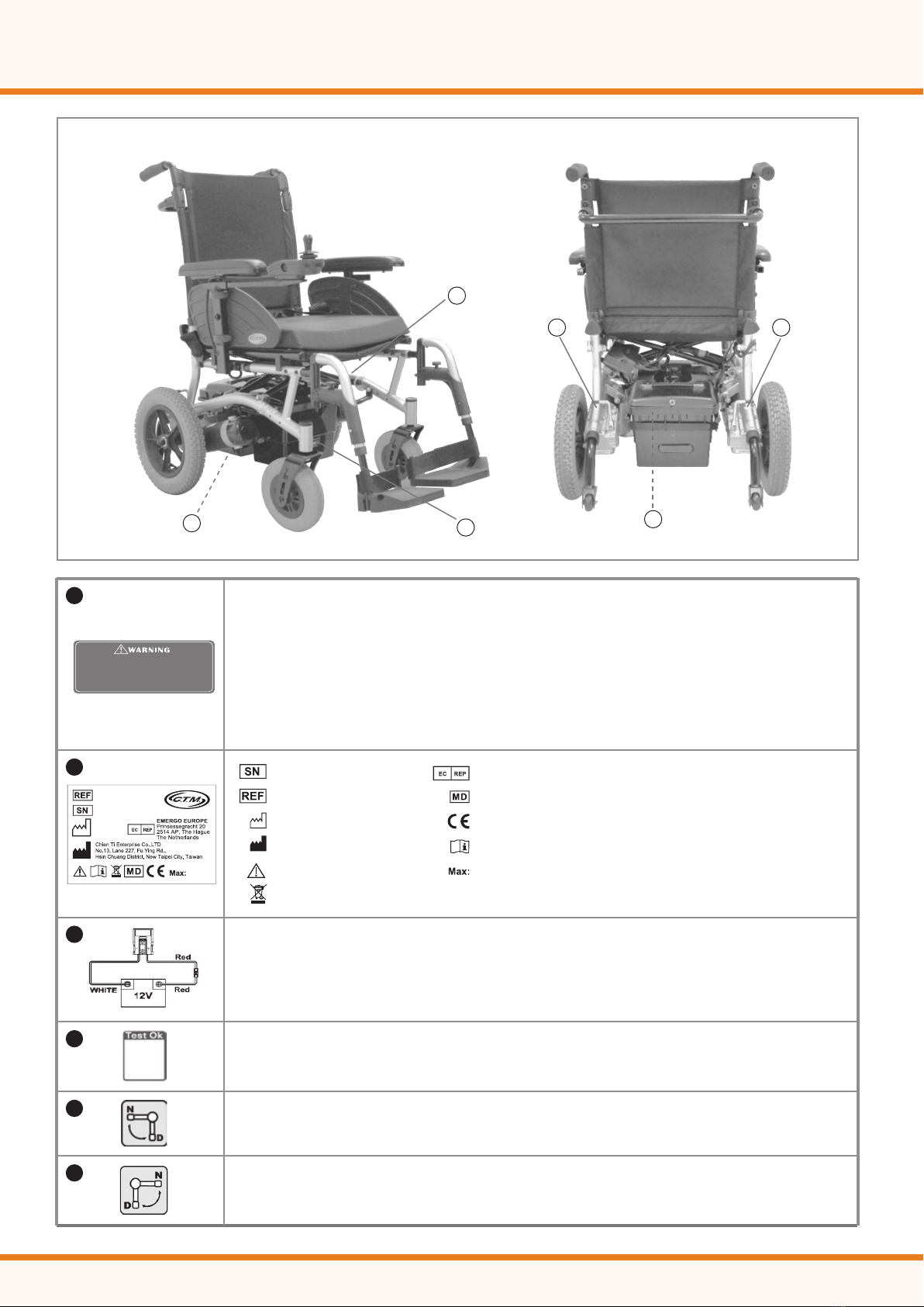
2. Mount all the electrical parts of the wheelchair system (motors, park brakes, batteries, Power
Module, Remote) on the wheelchair. for the physical dimensions of the LiNX LE System Power
Module, Remote and mounting recommendations.
3. Do not connect any cables before all the parts of the electrical system are mounted.
4. Connect the LiNX LE System Power Module to the motors the park brakes and the Remote.
5. Connect the LiNX LE System Power Module to the batteries.
CAUTION: Do not turn on the wheelchair yet.
CAUTION: Do not connect the positive terminal (B+) of the battery to the LiNX LE System
Power Module until the wheelchair is completely wired and ready for testing as described
in the Testing section.
6. Lift the wheelchair off the ground and check the installation thoroughly.
7. Program the system to the requirements of a particular wheelchair or user.
8. Test the system for functionality and safety.
Power up/down:
To switch ON the LiNX LE System, press the Power button. The Power button
is the only user input that can activate the system.
If the system is healthy, the Status indicator (through the Power button) will
light up green, and the Battery Gauge will display the current battery status.
If there is a fault with the system when powering up, the status indicator will indicate the fault with
a series of red ashes (see section 3 Diagnostics). If the fault is one that prevents the system from
driving, then the battery gauge will ash continuously.
To switch OFF the system, press the Power button; the system will power down and the Status
indicator will switch off.
The Power button is also used to perform an EMERGENCY STOP. See next section.
Emergency Stop:
If the user needs to stop the wheelchair quickly, the Power button can be pressed to perform an
EMERGENCY STOP. The wheelchair will come to a halt quickly; the rate is set by the Emergency
Deceleration parameter.
CAUTION: If this parameter is set too high, the user can lose balance or fall out of the chair.
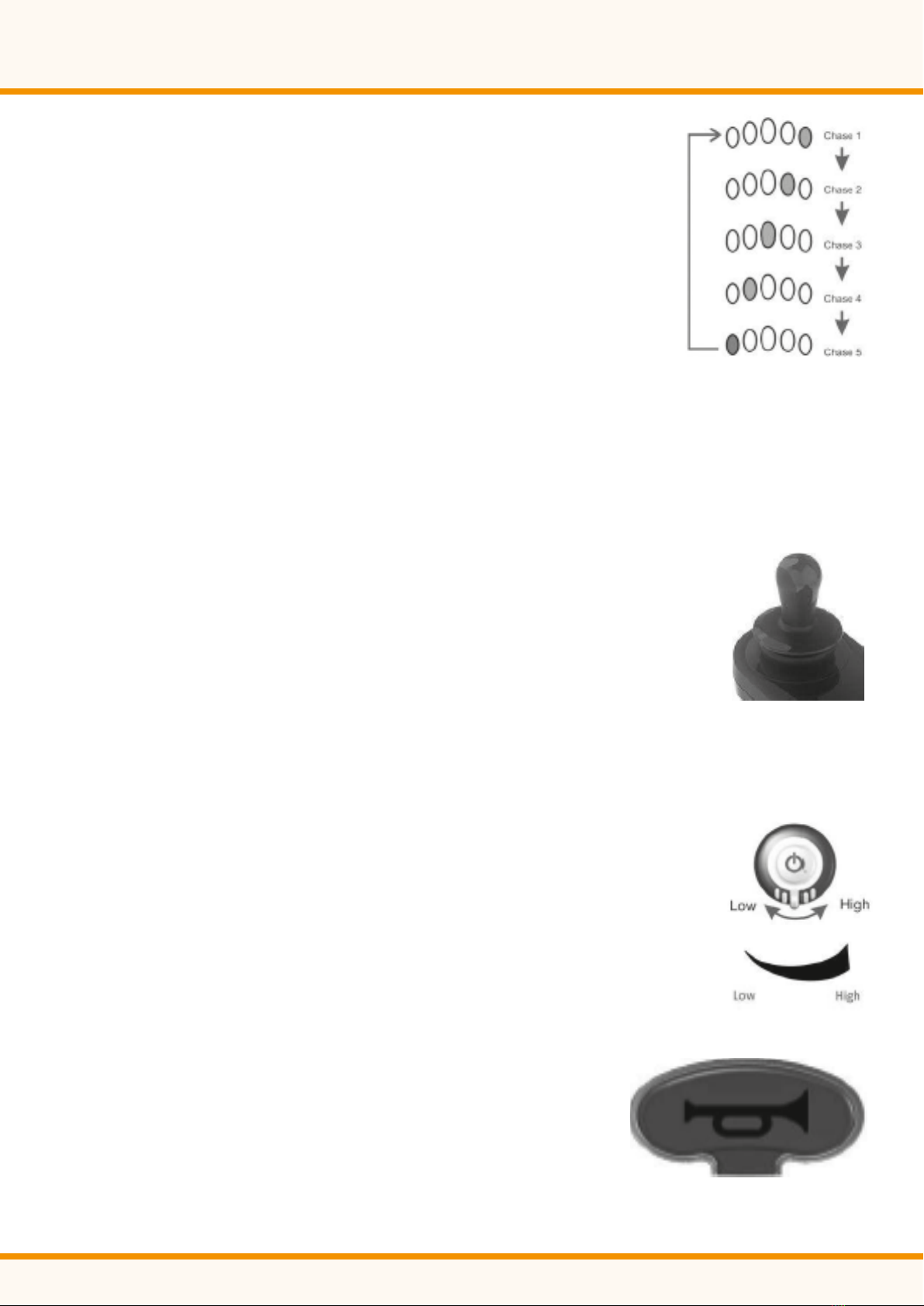
Drive Inhibit Indication:
Drive inhibit mode is indicated by the battery gauge with a right-to-left chase sequence.
The chase sequence starts with the green LED on the right-hand side, and one-by-one, each LED
will switch on and then off. When the sequence completes at the left-most red LED, it begins
08

again at the right-hand side.
The chase sequence continues until the error condition has been cleared.
OONAPU:
OONAPU (“Out Of Neutral At Power Up”) is a safety feature that prevents
accidental movement of the wheelchair, either when powering up, or when
the wheelchair comes out of an inhibit state.
If the LiNX LE System is turned on (or comes out of an inhibit state)
while the joystick is not in the centre position, an OONAPU warning is
displayed. During an OONAPU warning, the battery gauge LEDs will ash continually to alert
the user, and the chair will not drive. If the joystick is returned to the centre position within ve
seconds, the warning will clear and the wheelchair will drive normally.
However, if the joystick remains out of neutral for longer than ve seconds, an OONAPU error will
occur; the error is displayed by the Status indicator ashing red, and the chair will not drive.
To clear the error, return the joystick to the neutral position and power the unit OFF and then
on again.
The Joystick:
The joystick controls the direction and speed of the wheelchair.
When the joystick is deected from the centre position, the wheelchair
will move in the direction of the joystick movement.
The speed of the wheelchair is proportional to the joystick deection, so that the
further the joystick is moved from the centre position, the faster the wheelchair will travel.
Controlling Maximum Speed:
The speed dial allows the user to limit the maximum speed of the wheelchair (that is, the speed
when the joystick is fully deected) to suit their preference and environment.
The dial offers 10 discrete steps between the lowest speed (dial set to the left)
and the highest speed (dial set to the right).
As a visual reminder, a speed symbol (shown left) is positioned just below the
speed dial to indicate the low and high positions of the speed dial.
CAUTION: It is the responsibility of the wheelchair manufacturer to inform
the wheelchair user about the wheelchair’s stopping distances.
The Horn:
The Horn button is located above the Power button. Press the Horn
button to sound the horn. The horn will sound for as long as the
Horn button is pressed.
09

The Battery Gauge:
The battery gauge comprises ve different LEDs (1 x RED, 2 x AMBER,
2 x GREEN), situated above the Remote’s Horn button. The number of
LEDs lit depends on the status of the battery, as shown below.
The battery gauge LEDs are also used to display charging information.
See section 2.2 Battery charging for more details.
Normal Operation:
High Voltage Warning:
A high voltage warning is indicated by all LEDs on, and the green LEDs ashing.
This occurs when the battery voltage level has risen above the high voltage
warning set-point.
Low Voltage Warning:
A low voltage warning is indicated with the left-most LED ashing. This occurs
when the battery voltage level has decreased below its low voltage warning
set-point. Charge the battery immediately.
Cut-off Voltage:
When the battery voltage decreases below the battery cut-off voltage:
•The rst (red) LED will ash on the battery gauge.
•The status indicator (under the power button) will display a ash code 2 or 7.
•The horn will sound once every 10 seconds.
The Status Indicator:
The status indicator is located underneath the power button. When the LiNX LE System is not
powered up, the status indicator is not lit.
When the LiNX LE System is powered up, and there are no
faults with the system, the status indicator will be lit green.
If, when powered up, there is a fault with the system, then the status indicator will ash red.
The number of ashes will indicate the type of error.
Battery Gauge
Battery Gauge Battery Level
Fully Charged
Consider charging battery
Battery needs charging
This level is set by the Battery Gauge
Maximum parameter.
This level is set by the Batt Gauge
Minimum parameter.
Notes
Z
10

The XLR Charger Connector:
The XLR charger connector, which is located on the right-hand side of the
Remote, is used to connect to either a battery charger or the LiNX Access Key.
CAUTION: Make sure that the battery charger that is used with the vehicle has a drive
inhibit function that is correctly connected for use with the controller. The maximum
voltage on the inhibit pin must not exceed 3V if a battery voltage is to be detected when the
battery charger is connected. If you are not sure, ask your dealer or vehicle manufacturer.
The XLR charger connector on the Remote is to be used exclusively for the intended
purpose. Warranty will be voided if any unauthorised device is connected to this port.
The LiNX Communications Bus Connector:
The LiNX Communications Bus connector can be found on the lower front of the
Remote (see Figure 28: The Remote: user interface and connectors). The LiNX
Communications Bus loom plugs directly into this socket, providing the Remote
with both power and communication to the power module.
Battery Charging:
Plug the battery charger into the Remote’s XLR socket.
The Battery Gauge will indicate the system is being charged by
cycling between a left-to-right chase sequence, and then displaying
the approximate battery charge state at the end of the chase sequence.
Driving is prevented (inhibited) while the system is being charged.
The LE system does not have to be powered up when charging the
battery, however, if it is not powered up, then the battery gauge will not
display the charging state/ chase sequence.
CAUTION: The maximum charging current for the LiNX LE System is 6A.
The wheelchair manufacturer must specify an appropriate battery charger for the batteries
used in the wheelchair. The wheelchair manufacturer must also specify the maximum
current of any battery chargers to be used with the controller and warn against using
battery chargers of higher current ratings. The battery charger must have over-current
protection in the form of a non-resettable fuse. It is the responsibility of the wheelchair
manufacturer to manage the risks of battery over-charging and any related gas emissions.
To protect the wheelchair wiring from over currents while charging the batteries, chargers
must have the ability to reduce their current output when electrically shorted.
Error Indication:
If, when powered up, there is an error with the system, then the status indicator will
ash red. The number of ashes will indicate the type of error.
These are described in the table on the following page.
Fig. 28
11

Flash Code Error Description
1 Remote / joystick error
2 Network or configuration error
3 Left motor error
4 Right motor error
5 Left park brake error
6 Right park brake error
7 Module error (other than Remote)
For more information about the error,
and what to do about it, open the
logs within one of the programming &
diagnostic tools.
Free Wheel Operation:
To push the Powerchair by hand or in the event of a fault or battery failure the motors/gear boxes
can be released allowing the Power chair to be pushed.
The levers should be switched to the free wheel position
on the gear box by rotating them through 90º. Use the
manual brakes to park the chair.
CAUTION: Always re-engage the free wheeling device after use. Failure to do so may result
in injury
Wheels and Tyres:
Regularly check the condition of front and rear tyres for wear and tear. Contact your supplier for
replacements if necessary. Your Powerchair may have split rim wheels which are held together by
screws or bolts. When these are removed the wheel rim separates for easy access to carry out
puncture repairs or tyre replacements.
Disassembly and Storage:
1. Your Power chair can be disassembled and
folded for storage:
2. Fold the two footrest plates upwards (H1) and
press (H) button to swing away.
3. Remove kerb climber unit (if tted)
4. Release Support Brace by pressing
right side button (I).
Backrest Folding Device:
1. Press down the lever (K) to fold the backrest.
2. Disconnect plug and socket between battery boxes.
3. Pull off velcro strap (L). Pull to slide battery boxes from sliders.
4. Pull off velcro (M). Using both hands, grip front and rear of the seat upholstery (N) and pull up
to fold the chair.
5. To unfold the chair, place each hand on both seat tubes and push downward rmly. Slide
battery boxes into position, secure in place by velcro strap and reconnect cables.
I
J
H
H1
12

Batteries and Charging:
When your batteries are fully charged you should have sufficient power to give you all the mobility
required in a day. It is important that you understand how your batteries and charger work.
Batteries must be charged before using the power chair for the first time and are recommended
to be charged up to 10 - 14 hours after each day’s use.
Maintain the Batteries:
1. Batteries should be charged every night in a well ventilated room.
2. DO NOT place the power wheelchair near radiators or open fireplaces while charging.
3. DO NOT smoke or permit open flames in the immediate vicinity.
4. Turn the chair controller power off before charging.
5. It is advisable that the batteries be charged for a minimum of 10 hours per night to ensure
full battery storage capacity. The battery charger is an automatic current limiting device and
will shut off when the batteries are fully charged.
Charging the Batteries:
1. Position power chair next to a standard wall outlet.
2. Connect the battery charger to the wheelchair input battery charging socket, which is located on
the front of the controller.
3. Connect the battery charger to a standard wall power outlet.
4. Switch the power on.
CAUTION: Do not use batteries other than the recommended type for your chair and
never use a charger other than the one supplied for that purpose. If the chair is not used
for a long period of time arrange to have the batteries charged for at least one day (10-14
hours) every month, minimum. Periodically, check that the battery terminals are clean
and the connections are tight. Smear a thin film of petroleum jelly on the terminals to
guard against corrosion. Always wash your hands after handling batteries.
K
L
M
N
13
Indicator Functions: With bi-coloured LED light
Flash-rapid Red = Faulty
Flash Red = Standby
Solid Red = Charging
Solid Green = Fully Charged
Yellow = Power

Maintenance and Cleaning:
An electric wheelchair needs some basic attention to ensure it provides reliable service. We
recommend that the user ensures that the power wheelchair is checked regularly for maintenance
requirements and receives a thorough, annual maintenance check up.
Annual Maintenance:
We recommend that the chair has at least one full service per year from an authorized dealer.
This will ensure that your power chair is functioning properly and also helps prevent future
complications. This should include:
1. Checking the tires.
2. Checking the batteries and terminals.
3. Checking the controller program for the user’s needs.
4. Checking the frame.
5. Checking the upholstery condition.
Regular Maintenance and Cleaning:
1. Avoid knocking or bumping the controller, especially the joystick.
2. Avoid prolonged exposure of your power chair to extreme conditions, such as heat, cold,
or moisture.
3. Keep the controller clean.
4. Check that all controller connectors are tight and secured properly.
5. Never hose off your power chair or place it in direct contact with water.
6. Keep the upholstery and frame clean by wiping with a soft cloth, particularly after driving
through wet, sandy or muddy conditions. Do not use harsh abrasive materials when cleaning.
Do not apply liquid cleaners or solvents directly to the control box, battery charger or any
electrical connections.
7. Keep wheels free from lint, hair, sand and carpet bres.
8. Lightly oil axle pin, wheel axles and bearings once every three months, if necessary.
9. Inspect the tires. Tread depth should not be allowed to drop below 1/16”.
10.Use only recommended batteries and have batteries changed by Qualied Dealer if you have
doubts about your ability to lift the components.
11. Charge batteries regularly. Make sure the charger lead plugs are engaged properly in the
sockets. Do not disconnect by pulling the cord.
12.With the controller turned off, check the joystick. Make sure it is not bent or damaged and
that it returns to the center when you release it. Check the rubber boot around the base of
the joystick for damage. Visually inspect the boot. Do not handle or try to repair it. See your
authorized dealer for any questions.
13.Visually inspect the controller harnesses. Make sure that they are not frayed, cut or have any
wires exposed. See your authorized dealer if there is a problem with any of these harnesses.
14.Ensure that all parts of the controller system are securely fastened to your chair. Do not over
tighten any screws.
ELECTROMAGNETIC INTERFERENCE AND WARNINGS
CAUTION: It is very important that you read this information regarding the possible effects
of Electromagnetic Interference on your power chair.
Powered wheelchairs and motorized scooters may be susceptible to electromagnetic interference
(EMI), which is interfering electromagnetic energy (EM) emitted from sources such as radio
14

stations, TV stations, amateur radio (HAM) transmitters, two-way radios, and cellular phones. The
interference (from radio wave sources) can cause the power chair to release its brakes, move by
itself, or move in unintended directions. It can also permanently damage the power chair control
system. The intensity of the interfering EM energy can be measured in volts per meter (V/m).
Each power chair can resist EMI up to a certain intensity. This is called its “immunity level.” The
higher the immunity level, the greater the protection will be. At this time, current technology is
capable of achieving at least a 20 V/m immunity level, which would provide useful protection from
the more common sources of radiated EMI. The immunity level of this product is 20 V/m.
There are a number of sources of relatively intense electromagnetic elds in the everyday
environment. Some of these sources are obvious and easy to avoid. Others are not apparent and
exposure is unavoidable. However, we believe that by following the warnings listed below, your
risk to EMI will be minimized.
The sources of radiated EMI can be broadly classified into three types:
1. Hand-held portable transceivers (transmitters-receivers) with the antenna mounted
directly on the transmitting unit. Examples include: citizens band (CB) radios, “walkie talkie,”
security, re, and police transceivers, mobile telephones, and other personal
communication devices.
CAUTION: Some mobile telephones and similar devices transmit signals while they are ON,
even when not being used.
2. Medium-range mobile transceivers, such as those used in police cars, re trucks, ambulances,
and taxis. These usually have the antenna mounted on the outside of the vehicle.
3. Long-range transmitters and transceivers such as commercial broadcast transmitters (radio
and TV broadcast antenna towers) and amateur (HAM) radios.
CAUTION: Other types of hand-held devices, such as cordless phones, laptop computers, AM/FM
radios, TV sets, CD players, and small appliances, such as electric shavers and hair dryers, so far
as we know, are not likely to cause EMI problems to your power chair.
Power Chair Electromagnetic Interference:
Because EM energy rapidly becomes more intense as one moves closer to the transmitting
antenna (source), the EM elds from hand-held radio wave sources (transceivers) are of special
concern. It is possible to unintentionally bring high levels of EM energy very close to the power
chair control system while using these devices. This can affect power chair movement and
braking. Therefore, the warnings listed below are recommended to prevent possible interference
with the control system of the power chair.
CAUTION: Electromagnetic interference (EMI) from sources such as radio and TV stations,
amateur radio (HAM) transmitters, two-way radios, and mobile phones can affect the power
chair. Following the warnings listed on the following page should reduce the chance of
unintended brake release or power chair movement, which could result in serious injury.
15

1. Do not operate hand-held transceivers (transmitters-receivers), such as citizens band (CB)
radios, or turn ON personal communication devices, such as mobile phones, while the power
chair is turned ON;
2. Be aware of nearby transmitters, such as radio or TV stations, and try to avoid coming close
to them;
3. If unintended movement or brake release occurs, turn the power chair OFF as soon as it
is safe;
4. Be aware that adding accessories or components, or modifying the power chair, may make it
more susceptible to EMI; and
5. Report all incidents of unintended movement or brake release to the distributor listed on the
inside front cover of this manual. Note whether there is a source of EMI nearby.
Important Information:
1. 20 volts per meter V/m is a generally achievable and useful immunity level against EMI
(as of May 1994). The higher the level, the greater the protection.
2. The immunity level of this product is 20 V/m.
Warranty:
There is a comprehensive twelve-month warranty from the date on which your new scooter is
delivered. The warranty covers the scooter for repairs or replacement during this period. For more
details, please see the warranty conditions below.
•Any work or replacement part installation must be carried out by an authorised service agent.
•To apply to warranty should your scooter require repair, please contact the authorised dealer.
•Should any part of the scooter require repair or full or part replacement, as a result of a
manufacturing or material defect within warranty period, the work will be carried out free of
charge. Warranty period:
1. Frame: 2 year limited warranty.
2. Electronic parts: 12 months limited warranty.
3. Batteries: 6 month limited warranty.
•Any repaired or replaced parts will be covered by this warranty for the balance of the warranty
period on the powerchair.
•Parts replaced after the original warranty has expired will be covered by a three
months warranty.
•Consumable items supplied will not generally be covered during the normal warranty period
unless such items require repair or replacement clearly as a direct result of a manufacturing or
material defect. Such items include (among others): upholstery, tyres and batteries.
•The above warranty conditions apply to brand new powerchair purchased at the full retail price.
If you are unsure whether your powerchair is covered, check with the authorised dealer.
•Under normal circumstances, no responsibility will be accepted where the scooter has failed as
a direct result of:
1. The scooter part not having been maintained in accordance with the manufacturer’s
recommendations.
2. Failure to use the manufacturer’s specied parts.
3. The scooter or part having been damaged due to neglect, accident or improper use.
4. The scooter or part having been altered from the manufacturer’s specications or repairs
having been attempted before the service agent is notied.
The manufacturer reserves the right to alter, without notice, any weights, measurements or other technical data shown in this manual.
All figures, measurements and capacities shown in this manual are approximate and do not constitute specifications.
16

l
Further issues:
If the above troubleshooting does not help to resolve the issue please contact the authorised
dealer (page 2). Please have your serial no. to hand to provide to the authorised dealer, which
can be found on the battery pack.
Battery voltage is too high. This may occur if
overcharged &/or travelling down a long slope.
•If travelling down a slope, reduce your speed to
minimise the amount of regenerative charging.
•Check the battery and associated connections and
wiring.
The motor has been exceeding its maximum
current rating for too long. This may be due to a
faulty motor.
• Check the motor and associated connections and
wiring.
•Turn the controller off, leave for a few minutes and
turn back on again.
Either a park brake release switch is active or
the park brake is faulty.
• Check the park brake and associated connections
and wiring.
•Ensure any associated switches are in their correct
positions.
The throttle is out of neutral when turning the
controller on.
• Ensure the throttle is in neutral when turning the
controller on.
•The throttle may require re-calibration.
The throttle, speed limit pot or their associated
wiring may be faulty.
• Check the throttle and speed pot and associated
connections and wiring.
The motor or its associated wiring is faulty.
• Check the motor and associated connections and
wiring.
Battery low or
low battery fault
High battery
fault
Current limit
time-out
Throttle
OONAPU
Speed pot
fault
Motor voltage
fault
7
8
6
5
4
3
2
1
Other error
MeaningDescriptionFlash
The controller may have an internal fault.
• Check all connections & wiring.
The batteries are running low.
•Recharge the batteries for a minimum of 12 hours.
17
Park brake
uid

DAILY CHECK
Check point Inspection What to do if the inspection is failed
N-D lever
Horn
Throttles
Electro-
mechanical
brake and
Emergency
hand brake
Battery
Gauge
Rear
mirror (s)
Lighting
Contact your dealer.
‧Contact your dealer if battery gauge is
not working.
‧Recharge the battery immediately if low
‧Clean up the dirt by damp cloth.
‧Tighten the screw or clamping stem that
holds the mirror(s)
Contact your dealer.
Check for correct function
Pull the wigwag to test the scooter
movement
Pull the wigwag a little bit and
release it to test if brake works.
If your scooter comes with
emergency handbrake, please
check it as well.
Check if the battery gauge is
displayed and whether it is at
low power.
Check if the parts are clean and
firmly tighten to the scooter and
do not wobble.
Check if all lights, such as head
lights, rear lights, and turn signal
are functioning correctly.
WEEKLY CHECK
Check point Inspection What to do if the inspection is failed
Speed Dial
Knob
Armrests
Wheels/Tires
Motor
Battery
Charger
Contact your dealer.
Check for correct function
Check if the parts are clean and
firmly tighten to the scooter and
do not wobble. Tighten the screw
knob that holds the armrest.
Inflate the tire to the correct
pressure and check that
1.Drive wheels rotate without
wobbling.
2.Tire tread depth is not less than
0.5mm.
3.No foreign objects in tires.
Check for correct function
Check if the charger is functioning
correctly and the batteries are
charged.
MONTHLY CHECK
Check point Inspection What to do if the inspection is failed
Seat /
Upholstery
Electronics
Contact your dealer.
Check for movement and if it’s
worn
Check if all the battery cables and
connectors are firmly tighten to the
scooter
Please always check your scooter before you start your every journey.
18

19
Specification
Overall height
Weight w/batteries
Weight capacity
Curb climbable
Brake
Seat Back Angle
Seat Back Height
Motor size
Travel range
990 mm / 40”
63.2 kg / 139.3lbs - 63.5 kg / 140lbs - 65 kg / 143.5lbs
136 kg / 300lbs - 136 kg / 300lbs - 145 kg / 320lbs
25 mm / 1”
Electro-Mechanical
100 degree
470 mm / 18.5”
420W 4600 r.p.m
35 km / 21.7 Miles
Overall length
Front wheels
Battery Charger
Ground clearance
Turning radius
Seat type
Battery size
Battery charger
1040 mm / 41”
200 mm / 7.9”
5A Off Board
80 mm / 3.2”
850 mm / 33.5”
Padded Breathable Ballistic Nylon Back Rest W/
Adjustable Back Angle & Seat Belt
(2) 12V. 36Ah
19 km / 12 Miles
Overall width
Rear wheels
Max. speed
Grade climbable
Seat width
Battery weight
595 mm / 23.4” - 645 mm / 25.4” - 695 mm / 27.4”
320 mm / 13”
8 kmph / 5 mph
8 degree
410 mm / 16” - 460 mm / 18” - 510 mm / 20”
25 kg / 55 lbs
**Subject to change without notice. (Issue C 06/04/2022)
This manual suits for next models
1
Table of contents
Other Abilize Wheelchair manuals
Popular Wheelchair manuals by other brands

SHONAQUIP
SHONAQUIP Madiba2go Guide

DeVilbiss Healthcare
DeVilbiss Healthcare drive D-LITE Instructions for use

Evocare
Evocare LM9515 owner's manual

Loopwheels
Loopwheels Urban user manual

aidapt
aidapt Lenham VR231 Fixing and maintenance instructions

Sunrise Medical
Sunrise Medical Breezy Ultra 4 Brochure & specs