Abit KN8 ULTRA User manual

Introduction
KN8 Ultra-SOTES
KN8 Ultra
KN8
Motherboard
AMD Socket 939
User’s Manual
Hardware Setup
BIOS Setup Driver & Utility CD Appendix
About this Manual:
This user’s manual contains all the information you may
need for settin
g
up this motherboard. To read the user’s
manual of PDF format (readable by Adobe Reader), place
the “Driver & Utility CD” into the CD-ROM drive in your
system. The auto-run screen will appear, click the
“Manual” tab to enter its submenu. If not, browse the
root directory of the CD-ROM via the File Mana
g
er, and
double click the “AUTORUN” file.
AMD Socket 939 K8 Dual Core
ATX Motherboard
NVIDIA Chipset:
NF4 Ultra/NF4 Single Chip
2GHz HT
Dual DDR 400 DIMM Slots
GbE LAN w/Firewall
4x SATA 3Gb/s with
RAID 0/1/0+1
ABIT Silent OTES™ Technology
7.1 Channel Audio
* See the “Features & Specifications” of each model in
this manual for details.

KN8 Ultra-SOTES, KN8 Ultra, KN8
User’s Manual
English, 2nd Edition
May, 2006
Copyright and Warranty Notice
The information in this document is subject to change without notice and does not represent a
commitment on part of the vendor, who assumes no liability or responsibility for any errors that may
appear in this manual.
No warranty or representation, either expressed or implied, is made with respect to the quality,
accuracy or fitness for any particular part of this document. In no event shall the manufacturer be
liable for direct, indirect, special, incidental or consequential damages arising from any defect or
error in this manual or product.
Product names appearing in this manual are for identification purpose only and trademarks and
product names or brand names appearing in this document are the property of their respective
owners.
This document contains materials protected under International Copyright Laws. All rights reserved.
No part of this manual may be reproduced, transmitted or transcribed without the expressed written
permission of the manufacturer and authors of this manual.
If you do not properly set the motherboard settings, causing the motherboard to malfunction or fail,
we cannot guarantee any responsibility.
ii KN8 Ultra-SOTES, KN8 Ultra, KN8

Introduction
Contents
1. Introduction..................................................................... 1-1
Hardware Setup
BIOS Setup Driver & Utility CD Appendix
1.1 Features & Specifications .............................................................1-1
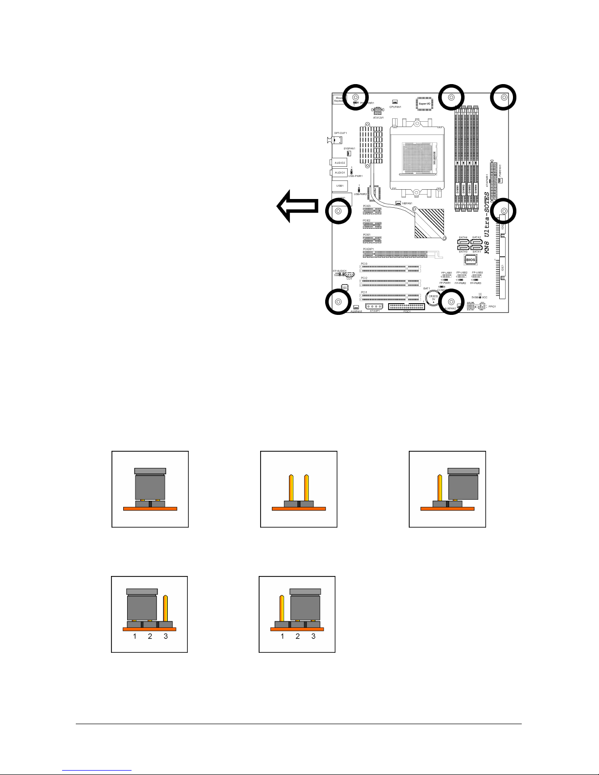
1.2 Motherboard Layout.....................................................................1-3
1.2.1 KN8 Ultra-SOTES.................................................................1-3
1.2.2 KN8 Ultra/KN8 ....................................................................1-4
2. Hardware Setup ............................................................... 2-1
2.1 Choosing a Computer Chassis.......................................................2-1
2.2 Installing Motherboard .................................................................2-1
2.3 Checking Jumper Settings ............................................................2-2
2.3.1 CMOS Memory Clearing Header and Backup Battery ..............2-3
2.3.2 Wake-up Headers................................................................2-5
2.4 Connecting Chassis Components...................................................2-6
2.4.1 ATX Power Connectors ........................................................2-6
2.4.2 Front Panel Switches & Indicators Headers............................2-7
2.4.3 FAN Power Connectors ........................................................2-8
2.5 Installing Hardware......................................................................2-9
2.5.1 CPU Socket 939 ..................................................................2-9
2.5.2 DDR Memory Slots ............................................................2-12
2.5.3 PCI Express X16 Add-on Slot (Install Graphics Card) ............2-13
2.6 Connecting Peripheral Devices ....................................................2-14
2.6.1 Floppy and IDE Disk Drive Connectors ................................ 2-14
2.6.2 Serial ATA Connectors .......................................................2-15
2.6.3 Additional USB 2.0 Port Headers.........................................2-16
2.6.4 Internal Audio Connectors..................................................2-16
2.6.5 Front Panel Audio Connection Header .................................2-17
2.6.6 PCI Express X1 Add-on Slots ..............................................2-18
2.6.7 PCI Add-on Slots ...............................................................2-18
2.7 Onboard Status Display.............................................................. 2-19
2.7.1 Power Source Indicators .................................................... 2-19
2.8 Connecting I/O Devices..............................................................2-20
3. BIOS Setup....................................................................... 3-1
3.1 SoftMenu Setup...........................................................................3-3
3.2 Standard CMOS Features..............................................................3-5
3.3 Advanced BIOS Features ..............................................................3-9
3.4 Advanced Chipset Features......................................................... 3-11
KN8 Ultra-SOTES, KN8 Ultra, KN8 iii

3.5 Integrated Peripherals................................................................3-14
3.6 Power Management Setup..........................................................3-18
3.7 PnP/PCI Configurations .............................................................. 3-21
3.8 PC Health Status........................................................................3-23
3.9 Load Fail-Safe Defaults ..............................................................3-25
3.10 Load Optimized Defaults...........................................................3-25
3.11 Set Password...........................................................................3-25
3.12 Save & Exit Setup .................................................................... 3-25
3.13 Exit Without Saving..................................................................3-25
4. Driver & Utility CD............................................................ 4-1
4.1 nVidia nForce Chipset Driver.........................................................4-2
4.2 Realtek Audio Driver ....................................................................4-3
4.3 Cool’n’Quiet Driver.......................................................................4-4
4.4 USB 2.0 Driver.............................................................................4-5
4.5 ABIT EQ (The Hardware Doctor Utility)..........................................4-6
4.6 FlashMenu (BIOS Update Utility)...................................................4-8
4.7 NVRaid Floppy Disk....................................................................4-10
5. Appendix .......................................................................... 5-1
5.1 Troubleshooting (How to Get Technical Support?)..........................5-1
5.1.1 Q & A.................................................................................5-1
5.1.2 Technical Support Form ......................................................5-4
5.1.3 UNIVERSAL ABIT Contact Information ..................................5-5
iv KN8 Ultra-SOTES, KN8 Ultra, KN8

Introduction
1. Introduction
1.1 Features & Specifications
CPU
• Supports AMD Athlon 64/64FX Dual Core 939-pin K8 CPU with 2GHz system bus
using Hyper Transport Technology
• Supports AMD K8 CPU Cool ‘n’Quiet Technology
Chipset
• NVIDIA NF4 Ultra single chip (For model “KN8 Ultra-SOTES” and “KN8 Ultra” only)
• NVIDIA NF4 single chip (For model “KN8” only)
Memory
• Supports 4 DIMM Dual DDR 400 non-ECC un-buffered memory
• Supports maximum memory capacity up to 4GB
NV SATA RAID
• Supports SATA RAID 0/1/0+1
• Support SATA 1.5Gb/s data transfer rate. (For model “KN8” only)
• Support SATA 3Gb/s data transfer rate. (For model “KN8 Ultra-SOTES” and “KN8
Ultra” only)
NV GbE LAN
• NVIDIA Gigabit Ethernet with NV Firewall ActiveArmor (For model “KN8
Ultra-SOTES” and “KN8 Ultra” only)
• NVIDIA Gigabit Ethernet (For model “KN8” only)
Audio
• Onboard 7.1 CH Audio CODEC
• Supports auto jack sensing
• Supports optical S/PDIF Out (For model “KN8 Ultra-SOTES” and “KN8 Ultra” only)
ABIT Engineered
• ABIT SoftMenu™Technology
• ABIT CPU ThermalGuard™Technology
• ABIT Silent OTES™Technology (For model “KN8 Ultra-SOTES” only)
Expansion Slots
• 1x PCI-E X16 slot
• 3x PCI-E X1 slots
• 3x PCI slots
Internal I/O Connectors
• 1x Floppy port supports up to 2.88MB
KN8 Ultra-SOTES, KN8 Ultra, KN8 1-1

• 2x Ultra DMA 133/100/66/33 IDE connectors
• 4x SATA 3Gb/s connectors (For model “KN8 Ultra-SOTES” and “KN8 Ultra” only)
• 4x SATA 1.5Gb/s connectors (For model “KN8” only)
• 3x USB 2.0 headers
• 1x FP-AUDIO header
• 1x CD-IN header
Rear Panel I/O
• ABIT Silent OTES™(For model “KN8 Ultra-SOTES” only)
• 1x PS/2 Keyboard connector
• 1x PS/2 Mouse connector
• 1x Serial port (For model “KN8 Ultra” and “KN8” only)
• 1x Parallel port (For model “KN8 Ultra” and “KN8” only)
• 1x S/PDIF Out (For model “KN8 Ultra-SOTES” and “KN8 Ultra” only)
• 1x AUDIO1 connector (Mic-In, Line-In, Line-Out)
• 1x AUDIO2 connector (Surround-Left / Surround-Right, Rear-Left / Rear-Right,
Center/Subwoofer)
• 1x RJ-45 Gigabit LAN port
• 4x USB 2.0 ports
Miscellaneous
• ATX form factor (305mm x 245mm)
※ Specifications and information contained herein are subject to change without
notice.
1-2 KN8 Ultra-SOTES, KN8 Ultra, KN8

Introduction
1.2 Motherboard Layout
1.2.1 KN8 Ultra-SOTES
KN8 Ultra-SOTES, KN8 Ultra, KN8 1-3

1.2.2 KN8 Ultra/KN8
1-4 KN8 Ultra-SOTES, KN8 Ultra, KN8

Hardware Setup
KN8 Ultra-SOTES, KN8 Ultra, KN8 2-1
2. Hardware Setup
In this chapter we will elaborate all the information you need upon installing this motherboard
to your computer system.
※ Always power off the computer and unplug the AC power cord before adding or
removing any peripheral or component. Failing to so may cause severe damage
to your motherboard and/or peripherals. Plug in the AC power cord only after
you have carefully checked everything.
※ Unless stated additionally, the motherboard layout in this chapter relies mainly
on KN8 Ultra-SOTES.
2.1 Choosing a Computer Chassis
• This motherboard carries an ATX form factor of 305 x 245 mm. Choose a chassis big
enough to install this motherboard.
• As some features for this motherboard are implemented by cabling connectors on the
motherboard to indicators and switches or buttons on the chassis, make sure your chassis
supports all the features required.
• If there is possibility of adopting some more hard drives, make sure your chassis has
sufficient power and space for them.
• Most chassis have alternatives for I/O shield located at the rear panel. Make sure the I/O
shield of the chassis matches the I/O port configuration of this motherboard. You can find
an I/O shield specifically designed for this motherboard in its package.
2.2 Installing Motherboard
Most computer chassis have a base with
many mounting holes to allow the
motherboard to be securely attached, and at
the same time, prevent the system from
short circuits. There are two ways to attach
the motherboard to the chassis base:
1. with studs
2. or with spacers
In principle, the best way to attach the board
is to use studs. Only if you are unable to do
this should you attach the board with spacers.
Line up the holes on the board with the mounting holes on the chassis. If the holes line up and
there are screw holes, you can attach the board with studs. If the holes line up and there are
only slots, you can only attach with spacers. Take the tip of the spacers and insert them into
the slots. After doing this to all the slots, you can slide the board into position aligned with slots.
After the board has been positioned, check to make sure everything is OK before putting the
chassis back on.

To install this motherboard:
1. Locate all the screw holes on
the motherboard and the
chassis base.
2. Place all the studs or spacers
needed on the chassis base
and have them tightened.
3. Face the motherboard’s I/O
ports toward the chassis’s rear
panel.
4. Line up all the motherboard’s
screw holes with those studs o
r
spacers on the chassis.
5. Install the motherboard with
screws and have them
tightened.
Face the chassis’s rear panel.
※ To prevent shorting the PCB circuit, please REMOVE the metal studs or spacers if
they are already fastened on the chassis base and are without mounting-holes
on the motherboard to align with.
2.3 Checking Jumper Settings
For a 2-pin jumper, plug the jumper cap on both pins will make it CLOSE (SHORT). Remove the
jumper cap, or plug it on either pin (reserved for future use) will leave it at OPEN position.
SHORT OPEN OPEN
For 3-pin jumper, pin 1~2 or pin 2~3 can be shorted by plugging the jumper cap in.
Pin 1~2 SHORT Pin 2~3 SHORT
2-2 KN8 Ultra-SOTES, KN8 Ultra, KN8

Hardware Setup
KN8 Ultra-SOTES, KN8 Ultra, KN8 2-3
2.3.1 CMOS Memory Clearing Header and Backup Battery
The time to clear the CMOS memory occurs when (a) the CMOS data becomes corrupted, (b)
you forgot the supervisor or user password preset in the BIOS menu, (c) you are unable to
boot-up the system because the CPU ratio/clock was incorrectly set in the BIOS menu.
This header uses a jumper cap to clear the CMOS memory and have it reconfigured to the
default values stored in BIOS.
• Pins 1 and 2 shorted (default): Normal operation.
• Pins 2 and 3 shorted: Clear CMOS memory.
To clear the CMOS memory and load in the default values:
1. Power off the system and disconnect with AC power source.
2. Set pin 2 and pin 3 shorted by the jumper cap. Wait for a few seconds. Set the jumper cap
back to its default settings --- pin 1 and pin 2 shorted.
3. Power on the system.
4. For incorrect CPU ratio/clock settings in the BIOS, press <Del> key to enter the BIOS setup
menu right after powering on system.
5. Set the CPU operating speed back to its default or an appropriate value.
6. Save and exit the BIOS setup menu.

CMOS Backup Battery:
An onboard battery saves the CMOS memory to keep the BIOS information stays on even after
disconnected your system with power source. Nevertheless, this backup battery exhausts after
some five years. Once the error message like “CMOS BATTERY HAS FAILED” or “CMOS
checksum error” displays on monitor, this backup battery is no longer functional and has to
be renewed.
To renew the backup battery:
1. Power off the system and disconnect with AC power source.
2. Remove the exhausted battery.
3. Insert a new CR2032 or equivalent battery. Pay attention to its polarity. The “+” side is its
positive polarity.
4. Connect AC power source and power on the system.
5. Enter the BIOS setup menu. Reconfigure the setup parameters if necessary.
CAUTION:
※ Danger of explosion may arise if the battery is incorrectly renewed.
※ Renew only with the same or equivalent type recommended by the battery
manufacturer.
※ Dispose of used batteries according to the battery manufacturer’s instructions.
2-4 KN8 Ultra-SOTES, KN8 Ultra, KN8

Hardware Setup
KN8 Ultra-SOTES, KN8 Ultra, KN8 2-5
2.3.2 Wake-up Headers
These headers use a jumper cap to enable/disable the wake-up function.
• PS2-PWR1:
Pin 1-2 shorted (Default): Disable wake-up function support at Keyboard/Mouse port.
Pin 2-3 shorted: Enable wake-up function support at Keyboard/Mouse port.
• USB-PWR1:
Pin 1-2 shorted: Disable wake-up function support at USB1 port.
Pin 2-3 shorted (Default): Enable wake-up function support at USB1 port.
• USB-PWR2:
Pin 1-2 shorted: Disable wake-up function support at USB2 port.
Pin 2-3 shorted (Default): Enable wake-up function support at USB2 port.
• FP-PWR1:
Pin 1-2 shorted: Disable wake-up function support at FP-USB1 port.
Pin 2-3 shorted (Default): Enable wake-up function support at FP-USB1 port.
• FP-PWR2:
Pin 1-2 shorted: Disable wake-up function support at FP-USB2 port.
Pin 2-3 shorted (Default): Enable wake-up function support at FP-USB2 port.
• FP-PWR3:
Pin 1-2 shorted: Disable wake-up function support at FP-USB3 port.
Pin 2-3 shorted (Default): Enable wake-up function support at FP-USB3 port.

2.4 Connecting Chassis Components
2.4.1 ATX Power Connectors
These connectors provide the connection from an ATX power supply. As the plugs from the
power supply fit in only one orientation, find the correct one and push firmly down into these
connectors.
ATX 24-Pin Power Connector:
The power supply with 20-pin or 24-pin cables can both be connected to this 24-pin connector.
Connect from pin-1 for either type. However, a 20-pin power supply may cause the system
unstable or even unbootable for the sake of insufficient electricity. A minimum power of 300W
or higher is recommended.
ATX 12V 4-Pin Power Connector:
This connector supplies power to CPU. The system will not start without connecting power to
this one.
Auxiliary 12V Power Connector:
This connector provides an auxiliary power source for devices added on PCI
Express slots.
2-6 KN8 Ultra-SOTES, KN8 Ultra, KN8

Hardware Setup
KN8 Ultra-SOTES, KN8 Ultra, KN8 2-7
2.4.2 Front Panel Switches & Indicators Headers
This header is used for connecting switches and LED indicators on the chassis front panel.
Watch the power LED pin position and orientation. The mark “+” align to the pin in the figure
below stands for positive polarity for the LED connection. Please pay attention to connect these
headers. A wrong orientation will only cause the LED not lighting, but a wrong connection of
the switches could cause system malfunction.
• HLED (Pin 1, 3):
Connects to the HDD LED cable of chassis front panel.
• RST (Pin 5, 7):
Connects to the Reset Switch cable of chassis front panel.
• SPKR (Pin 13, 15, 17, 19):
Connects to the System Speaker cable of chassis.
• SLED (Pin 2, 4):
Connects to the Suspend LED cable (if there is one) of chassis front panel.
• PWR (Pin 6, 8):
Connects to the Power Switch cable of chassis front panel.
• PLED (Pin 16, 18, 20):
Connects to the Power LED cable of chassis front panel.

2.4.3 FAN Power Connectors
These connectors each provide power to the cooling fans installed in your system.
• CPUFAN1: CPU Fan Power Connector
• NBFAN1: Chipset Fan Power Connector
• SYSFAN1: System Fan Power Connector
• PWRFAN1, AUXFAN1~2: Auxiliary Fan Power Connector
※ These fan connectors are not jumpers. DO NOT place jumper caps on these
connectors.
2-8 KN8 Ultra-SOTES, KN8 Ultra, KN8

Hardware Setup
KN8 Ultra-SOTES, KN8 Ultra, KN8 2-9
2.5 Installing Hardware
※ DO NOT scratch the motherboard when installing hardware. An accidentally
scratch of a tiny surface-mount component may seriously damage the
motherboard.
2.5.1 CPU Socket 939
※ DO NOT touch or bend the delicate pins on the CPU whenever you are holding it.
The installation procedures vary with different types of CPU fan-and-heatsink assembly. The
one shown here is served for DEMO only. For detailed information on how to install the one
you bought, refer to its installation guidelines.
1. Pull out the socket lever away from the
socket and fully lift it up over 90-degree
angle.
2. Locate and align the triangle mark with
both the CPU and the socket body.
Vertically place the CPU with its pin-side
down into the socket.
Be careful to insert the CPU into the
socket. The CPU only fits in one
orientation with the socket. DO NOT
force the CPU into the socket.

3. After placing the CPU into position, push
the socket lever down into its locked
position to secure the CPU. The lever
clicks when it’s locked into position.
4. The heatsink for CPU may have thermal
interface material attached to its
bottom. If not, applying a few squeeze
of thermal paste to the CPU die will help
to increase the contact.
5. Place the heatsink and fan assembly
onto the retention frame. Match the
heatsink clip with the socket
mounting-lug. Hook the spring clip to
the mounting-lug.
Put the CPU Fan down on the retention
module and snap the four retention legs
of the cooling fan into place.
6. On the other side, push the retention
clip straight down to lock into the plastic
lug on the retention frame.
2-10 KN8 Ultra-SOTES, KN8 Ultra, KN8

Hardware Setup
KN8 Ultra-SOTES, KN8 Ultra, KN8 2-11
7. Flip the lever over to lock the heat sink
in place.
8. Connect the CPU cooling fan power
cable to the CPUFAN connector on this
motherboard.
※ The motherboard in this illustration is served for DEMO only, may not be the
same type or model as the one described in this user’s manual.
※ A higher fan speed will be helpful for better airflow and heat-dissipation.
Nevertheless, stay alert to touch any heatsink since the high temperature
generated by the working system is still possible.

2.5.2 DDR Memory Slots
This motherboard provides four 184-pin DDR DIMM slots for Single/Dual Channel DDR
400/333/266 memory modules with memory expansion size up to 4GB.
To reach the performance of Dual Channel DDR, the following rules must be obeyed:
• For a 2-DIMM dual-channel installation:
Populate DIMM modules of the same type and size on slots [DIMM1]+[DIMM2], or slots
[DIMM3]+[DIMM4].
• For a 4-DIMM dual-channel installation:
Populate 2 DIMM modules of the same type and size on slots [DIMM1]+[DIMM2], and
another 2 DIMM modules of the same type and size on slots [DIMM3]+[DIMM4].
※ [DIMM1] and [DIMM2] slots are made of the same color.
[DIMM3] and [DIMM4] are made of another same color.
Usually there is no hardware or BIOS setup requires after adding or removing memory modules,
but you will have to clear the CMOS memory first if any memory module related problem
occurs.
2-12 KN8 Ultra-SOTES, KN8 Ultra, KN8
This manual suits for next models
1
Table of contents
Other Abit Motherboard manuals