Abit PD5NE User manual

TableofContents
Chapter 1IntroductionofPD5NFeatures
¬PD5N..........................................................................................1-2
lSpecifications.........................................................................1-2
lLayoutdiagram......................................................................1-4
¯Systemblockdiagram................................................................1-11
Chapter 2InstallingtheMainboard
¬StandardExternalConnectors......................................................2-3
-JumpersandSwitches................................................................2-10
®PresentationandInstallationoftheCPU....................................2-11
¯InstallingSystemMemory
¡i
DRAMMemory
¡j
.........2-21
Chapter 3IntroductionofBIOS
¬StandardCMOSSetup Menu.......................................................3-4
-BIOSFeaturesSetup Menu.........................................................3-6
®ChipsetFeaturesSetup Menu.....................................................3-12
¯PowerManagementSetup Menu................................................3-14
°PCI&OnboardI/OSetup..........................................................3-18
±LoadBIOSDefaults..................................................................3-23
²LoadSetup Defaults..................................................................3-23
³PasswordSetting.......................................................................3-24
´IDEHDD AutoDetection.........................................................3-35
Chapter 4VGAInstallation
AppendixAQuickInstallation
AppendixBIntelPentiumCPUs
AppendixCAMD-K5CPUs

Chapter1-2
AppendixDCyrix6x86 CPUs
AppendixEGeneralDiscussionaboutHDD Installation
AppendixFTechnicalSupport
AppendixGFlashBIOSUserInstructions

IntroductionofPD5NFeatures1-1
Chapter1Introduction ofPD5N
Features
ThePD5NhavebeenespeciallydesignedforFileserver,Workstationand
Professionalusers.Itcansupportawiderangeofprocessors,includingall
IntelCPUs(P54C)andIntelCPUswithMMX(P55C),aswell asall AMD-
K5/K6andCyrix6x86/6x86L/6x86MXCPUs.Italsotakesintoaccount,as
muchaspossible,all futureCPUs.
ThePD5NusesDIPswitchesorjumpers.
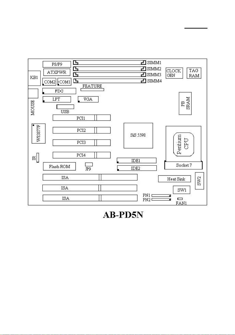
ThePD5NusesSIS5598 serieschipsets,andhas512KLevel-2Pipeline
BurstSRAMonboard.
72-pinSIMM slotsmeettherequirementsforall memoryconfigurations
requiredbyhighlevelcomputing.The72-pinSIMM slotssupport
traditionalFastPageandEDO DRAMasamemorystandardfornext
generation64-bitsystems.The72-pinSIMM slotshavebeenreservedtomeet
requirementsforbothpresentandfutureupgrades.
ThePD5NprovidestwoUniversalSerialBus(USB)portsandmeetsthe
ConcurrentPCIRev.2.1standard.ItalsosupportsIDEinterface forFast
HDD (Mode0~4)andUltraDMA/33,aswell asIDEBusMaster.These
featuresalsomeetpresentandfutureinterface standardsandneeds.
ThePD5NBuilt-inhigh-performance 64 bitGUIaccelerator.High
resolutionmodesincluding1024 ¡Ñ 768 ¡Ñ 64KHicolorsand1600 ¡Ñ
1200 ¡Ñ 256 colors.ItalsosupportsMPEGandlivevideoplayback.
SystemBIOSfeaturesincludePlug-and-Play(PnP),Advanced
ConfigurationPowerInterface (ACPI),thenewestDesktopManagement
Interface (DMI),aswell asPD5N’suniqueCPUoperatingfrequencyand
voltagesetup featureinordertomeetmoderncomputingdemands.

1-2Chapter1
¬
Specifications
1.SupportAT/ATXpowersupply
2.AdjustmentforFrequencyandVoltage
UsingDIPswitchorjumperwirestoadjustthefrequencyandvoltage
onthemainboard
3.UsesZIFCPUSocket7foreasyCPUinstallation
lSupportswitchingpowerforCPUtogetmorestableenvironment
lSupportsIntelPentiumCPUs:75~200MHzandP55CCPUswith
MMX(166~233MHz)
lSupportsall AMDsixthgenerationAMD-K5™CPUs:
75~166MHz,AMD-K6™CPUs:166MHz,200MHz,233MHz
lSupportsall Cyrixsixthgeneration6x86™CPUs:P120+,P133+,
P150+,P166+,P166+L,P200+,P200+Land6x86MX
lReservedcircuitrysupportsfuturesixthgenerationCPUs
4.Chipset
lSIS5598 chipset
lSupportsstandardversionPCI2.1
5.L2CacheMemory
l256Kor512Kofcachememory(PipelineBurstSRAM)
6.SystemDRAM
lFour72-pinSIMM sockets:supportFPandEDO DRAM
lUpto384MBmemoryconfigurationpossible
7.SystemBIOS
lAWARDBIOS
lSupportsPlug-and-Play(PnP)
lSupportsAdvancedConfigurationPowerInterface (ACPI)
lSupportsDesktopManagementInterface (DMI)
8.GraphicandvideoAccelerator
lBuilt-in64 bitGUIaccelerator
lSupportsvideoscaling,overlapandcolorspace conversion
lSupportsDDC1andDDC2BSpecification
lVideomemory:sharedsystemmemory
9.MultiI/Ofeatures

IntroductionofPD5NFeatures1-3
l
TwoUniversalSerialBus(USB)ports
l
FourfastIDEchannels(PIOmode0~4,Ultra“DMA/33”andBus
Master)
lOneEPP/ECPparallelportandtwo16550Aserialports
l
Twofloppydiskdriveconnectors(FDD)(360K,720K,1.2M,
1.44Mand2.88M)
l
SupportPS/2typemouse
10.Otherfeatures
l
StandardATarchitecturedimensions
l
FourISAbusslotsandfourPCIbusslots
l
Supports3-MODEforaspecialJapanesefloppydiskdrive
l
Supportstwobootableharddisks--abletoruntwodifferent
operatingsystems
l
SupportsIDEinterface CDROMandLS-120 typefloppydiskdrive
(Bootonly)
lPD5NisusingDIPswitchtoconfiguremainboard,theREDDIP
switchisusingtosetup theCPUvoltage-VCOREandVIO.The
BLUEDIPswitchisusingtosetup theCPUFrequencyandRating.
Note:All brandnamesandtrademarksarethepropertyoftheirrespectiveowners.

1-4Chapter1
-
Layoutdiagram
Fig1-1Layoutdiagram

IntroductionofPD5NFeatures1-5
®
Systemblockdiagram
Host BUS
Control
Address
Data
Cntrl
Tag Cntrl
TIO[0..7]
CACHE
(SRAM)
TAG
Cntrl
Addr
ECC
Data
Control
Address/Data
PCI BUS
Serial
LPT
FDC
PCI Device(s)
ISA Device(s)
Main
Memory
(DRAM)
USB
1USB
2
Universal Serial Bus
SiS 5598
CD ROM&
Hark Disk
ISA BUS
Winbond
w83877f
Pentium Processor
3.3v
VGA
TM
Fig.1-4Systemblockdiagram


InstallingtheMainboard 2-1
Chapter2Installing the
Mainboard
ThisPD5Nmainboardnotonlyprovidesall standardequipmentforclassic
personalcomputers,butalsoprovidesgreatflexibilityformeetingfuture
upgradedemands.Thischapterwill introduce stepbystepall thestandard
equipmentandwill alsopresent,ascompletelyaspossiblefutureupgrade
capabilities.Thismainboardisabletosupportall IntelPentiumincluding
P55CwithMMX,Cyrix6x86,6x86L,6x86MXandAMD-K5/K6processors
nowonthemarket.(Fordetails,see specificationsinChapter1.)
However,wecannotguarantee thatthedescriptiongiveninthismanualonthe
circuitryofyourmainboardwill workforprocessorsnotlistedinChapter1.
Forexample,theoperatingvoltageofCyrix’snextgenerationCPUsisunknown
atthepresenttime.Thuswewerenotabletoincludethesespecificationsin
yourmotherboard.Wewill supplyfurtherinformationaboutCPUsupport
whennewCPUsarriveonthemarket.
Thischapterisorganizedaccordingthefollowingfeatures:
ŒStandardexternalconnectors
•Jumpersandswitches
ŽPresentationandInstallingoftheCPU.
•Installingthesystemmemory.
NNNN
Before proceedingwiththeinstallation
Beforeinstallingthemainboardpleasebesuretoturnoff ordisconnectthe
powersupplyunit.Beforemakinganymodificationstothehardware
configurationofthemainboard,thepowersupplytoanyareasofthemainboard
youplantomodifyshouldbeturnedoff toavoidunnecessarydamagetothe
hardware.

2-2Chapter2
&
User friendlyinstructions
Ourobjectiveistoenablethenovice computerusertoperformthe
installationbythemselves.Wehaveattemptedtowritethisdocumentina
veryclear,conciseanddescriptivemannertohelpovercomeanyobstaclesyou
mayface duringinstallation.Pleasereadourinstructionscarefullyand
followthemcarefullystep-by-step.

InstallingtheMainboard 2-3
¬
StandardExternalConnectors
Insidethecaseofanycomputerseveralcablesandplugshavetobe
connected.Thesecablesandplugsareusuallyconnectedone-by-oneto
connectorslocatedonthemainboard.Youneedtocarefullypayattentionto
anyconnectionorientationthecablesmayhaveand,ifany,notice thepositionof
thefirstpinoftheconnector.Intheexplanationsthatfollow,wewill
describethesignificance ofthefirstpin.
PN1-KeylockconnectorPleasepayattention topinposition and orientation
Thisconnectorhasaspecificorientation.Connectthefive-threadkeylock
connectorcabletothePN1connectorpinsonthemainboard.
PinnumberNameorsignificance ofsignal
1+5VDC
2Noconnection
3Ground
4Keyboardinhibit Signal
5Ground
The“keylockswitch”isusedtolockthecomputer’skeyboard.
Thisdisablesthekeyboardsothatunauthorizedpersonscannot
useit.Whenthisfunctionisinuse,youwill needtouse
theunlockkeytoactivatethekeyboard.
Computer
K
n
o
w
l
e
d
g
e

2-4Chapter2
PN1-PowerON/OFF switch
Thereisnospecificorientation.Since mostcasesdonotsupportthisfeature,
mostofyouignorethisinstruction.
PinnumberNameorsignificance ofthesignal
10 Poweron/off
11 Ground
PN1-SMISwitch
Thereisnospecificorientation.Connectthetwo-threadcabletothePN1
connectorpinsonthemainboard.Since mostcasesdonotsupportthis
feature,mostofyouignorethisinstruction.Furthermore,thisfeatureisnot
necessaryasitisalreadyapartofthemainboard.
PinnumberNameorsignificance ofthesignal
13 +5VDC
14 Ground
PN1-HDD LEDconnector
Thisconnectorhasaspecificorientation.Connectthetwo-threadIDELED
connectorcableattachedtothecasetotheIDELEDconnectoronthe
mainboard.
PinnumberNameorsignificance ofsignal
7LED’sCathode
8LED’sAnode
PN2-Speakerconnector
Thereisnospecificorientation.Connectthefour-threadspeakercableto
thePN2connectorpinsonthemainboard.
PinnumberNameorsignificance ofsignal
4+5VDC
5Ground
6Ground
7SoundSignal

InstallingtheMainboard 2-5
PN2-HardwareResetconnectors
Thereisnospecificorientation.Connectthetwo-threadhardwarereset
cabletothePN2connectorpinsonthemainboard.
PinnumberNameorsignificance ofsignal
1Hardwareresetsignal
2Ground
FAN1-CPUFanpowerconnector
Thishasaspecificorientation.Connectthethree-threadsCPUfancabletothe
FAN1connector.
PinnumberNameofthesignalorsignification
1Ground
2+12V
3Ground
IR-InfraredremoteConnectors(JP10)
Watchthepinnumberandtheorientation.
Thishasaspecificorientation.Yourmainboardsupportsthisfeature,butyou
mustbuytheinfraredremotedevice asanoption.
PinnumberNameofthesignalorsignification
1+5VDC
2Noconnection
3Receivedata
4Ground
5Transmit data
ATXPWR-ATXPowerinputConnectors
Thesehaveaspecificorientation.Thethree warningmarksindicatethatifyou
makeamistakeinpinnumberorconnectionorientation,youcoulddestroyyour
equipment.Duringinstallation,youjustneedtoconnecttothecorrectpinsand

2-6Chapter2
inthecorrectorientation,andtoconnectconnectorofthepowersupplyunitto
theconnectoronthemainboard.
PinnumberNameofthesignalor
significationPinnumberNameofthesignalor
signification
1+3.3VDC11 +3.3VDC
2+3.3VDC12 -12VDC
3Ground 13 Ground
4+5VDC14 PS_ON
5Ground 15 Ground
6+5VDC16 Ground
7Ground 17 Ground
8POWERGOOD 18 -5VDC
9+5VDC19 +5VDC
10 +12VDC20 +5VDC
P8/P9-ATPowerinputConnectors
Thesehaveaspecificorientation.Thethree warningmarksindicatethatifyou
makeamistakeinpinnumberorconnectionorientation,youcoulddestroyyour
equipment.Duringinstallation,youjustneedtoconnecttothecorrectpinsand
inthecorrectorientation,andtoconnectconnectorsP8andP9ofthepower
supplyunittotheconnectorsonthemainboard.
PinnumberNameofthesignalor
significationPinnumberNameofthesignalor
signification
1POWERGOOD 7Ground
2+5VDC8Ground
3+12VDC9-5VDC
4-12VDC10 +5VDC
5Ground 11 +5VDC
6Ground 12 +5VDC

InstallingtheMainboard 2-7
Mouse-PS/2Mouseconnector(J4)
Watchthepinnumberandtheorientation
Thishasaspecificorientation.Connectthesix-threadsPS/2Mousecable
providedtotheconnectoronthemainboard.
PinnumberNameofthesignalorsignification
1Mousedata
2Noconnection
3Ground
4+5VDC
5Ground
6Mouseclock
The“PS/2MousePort”isdifferentfromCOM1orCOM2serial
portstowhichyoucanalsoconnectaMouse.Thismainboard
featuresanextraPS/2Mouseport,sowhenyoubuyamouse,
besurethatitisaPS/2Mousebeforeconnectingittothisport.
ButifyoucannotfindanyPS/2Mouse,youcanstill useCOM1
orCOM2toconnectaserialmousetoyourcomputer.
KB1-KeyboardConnector
Thishasanorientationpin.Connectyourkeyboardconnectortotheconnector
onthemainboard.
PinnumberNameofthesignalorsignification
1Keyboardclock
2Keyboarddata
3Noconnection
4Ground
5+5VDC
I/O Portconnectors
Watchthepinnumberandtheorientation
ConnectornamePinnumberNameoftheperipheralconnected
IDE1 40 IDEChannel1
Computer
knowledge

2-8Chapter2
IDE2 40 IDEChannel2
FDC34 Floppy Diskconnector
LPT26 Parallelportconnector
COM1 10 SerialportCOM1connector
COM2 10 SerialportCOM2connector
VGA16 VGAconnector
Feature26 FEATUREconnector
USB16 UniversalSerialBusconnector

InstallingtheMainboard 2-9
-
Jumpersand Switches
CCMOS(JP9) : DeletethecontentsoftheCMOS
Thisjumperissetonpins1and2atthefactory,inorderforthe
computertofunctionnormally,sopleasedonotchangethissetting.
Themainfeatureofthisjumperistosolvesituationswherethe
computercrashesduetoimproperusage.Forinstance:
lYouhaveforgottenthepasswordyouset.
lYouhavechangedinappropriatelythesettingsintheBIOS
menu.
lYouwanttochangetheversionofflashBIOS.
All theseerrorsareveryserious,youmustavoidthem.Butifyou
havemadeoneoftheseerrors,thisjumpercansaveyourlife.First
turnoff thepowersupplyandopenthecomputercase,thanplace the
jumperonpins2and3inordertosaveyourcomputer.Butifyouuse
yourcomputernormally,youshouldnotneedtousethisfeature.
AfteryouhavedeletedtheCMOSinformation,thecomputerissaved,but
youstill havetogobacktotheBIOSSetup menu,andresetonebyoneall
thespecifications:CPU,date,hour,FDD andHDD parameters.etc., before
yourcomputerwill getbackintonormaloperation.

2-10 Chapter2
®
Presentationand InstallationoftheCPU
Since 1996,everytwoorthree months,Inteladdsnewmodelstothe
PentiumCPUseries.ThatiswhytheCPUmarketisfilledwithalotofdifferent
modelsandbrands.All CPUshavedifferentelectricalspecifications.That’swhy
installingaCPUisbecomingmoreandmorecomplex.Youcan’thelpthat,
becauseeverybodywantstobeabletoupgradeitshardware.So,youhaveto
takeabitoftimetoreadthissection,inordertobeabletoinstall acheaperand
betterprocessor.
ThePD5Nmainboarddoesnotonlysupportall theCPUslistedinthe
specifications,butalsohasreservedseveralcircuitsinordertobeableto
supportfutureprocessors.Butbeforewegofurtherinourpresentation,we
mustclarifythat“wehaveonlytestedtheCPUslistedinChapter1”,wecannot
guarantee thatthisboardwill beabletosupportfutureproducts,becausewe
cannotforecastfuturedevelopments.Butwewill doourbesttosupportany
possibleCPU.
Relatedterminology :
Externalclock
AlsoreferredtoastheexternalCPUclock,or“Busclock”,itistheinput
clockoftheCPU.Forinstance,IntelPentiumP90,P120 andP150 all have
a60MHzexternalCPUclock,buthavedifferentinternalclockmultiplier
factors.
Clockmultiplierfactor
TherealoperationclockwithintheCPUisthemultipleoftheexternal
clock.Werefertothisfactorastheclockmultiplierfactor.Thefour
factorspossibleare1.5,2,2.5and3.ThefactordiffersfromoneCPUto
another.Forinstance,theIntelPentium166 CPUhasa66MHzexternal
clock,withamultiplierfactorof2.5,sothatthespeedoftheinternalclock
is66MHzx2.5.

InstallingtheMainboard 2-11
Internalclock
AlsoreferredtoastherealinternalCPUclock,itistheactualinternal
operatingclockoftheCPU.TheInternalClockisamultipleoftheexternal
clockandoftheclockmultiplierfactor.Forinstance,theIntelPentium90
CPUhasa60MHzexternalclockanditsclockmultiplierfactoris1.5;the
IntelPentiumP133 CPUhasa66MHzexternalclockanditsclock
multiplierfactoris2.
InternalCPUclock=clockmultiplierfactor*externalCPUclock
ATBusclock
AlsoreferredtoasISASPEED,orATCLOCK,orevenISABusclock.
Tenyearsago,theoriginalspecificationofATBusclockinstalledinthe
firstgenerationPC/ATcomputerswas8MHz,thismeansthatthereare
someinterface cardswhichcanonlyworkat8MHz.Inordertoguarantee
compatibilitywitholderhardware,westill support8MHzATBusclock,
butifyourinterface cardisnewerorfaster,youcanchooseahigherspeed
fortheATBusclock,inordertoincreasethetransmissionrateofthe
interface cards.Butwerecommendyounottobetoo ambitious.An8MHz
setup ensuresmaximumcompatibility.
CPUVoltage-Vcoreand Vio
Fromthevoltagepointofview,586 seriesCPUcanbedividedintotwo
categories:singlevoltageCPUanddualvoltageCPUs.Singlevoltage
CPUsinclude:IntelPentiumP54Cseries,AMD-K5andCyrix6x86,etc.
DualvoltageCPUsinclude:IntelP55CwithMMX,futureAMD-K6CPUs,
Cyrix6x86Land6x86MX.
ThevoltageofdualvoltageCPUshastwocomponents:VcoreandVio.
Vcoreprovidesall thepowerforinternalprocessing,anditspower
consumptionisquiteimportant.Vioprovidesthepowernecessaryforthe
externalinterface oftheCPU.

2-12 Chapter2
P-Rating
TheP-RatingwasdefinedbysomemanufacturersotherthanInteltorate
theperformance oftheirCPUincomparisonwithIntelPentiumCPUs.For
instance,Cyrix6x86 P166+hasahigheractualspeedcomparedwithIntel
PentiumP166,itsinternalclockneedsonly133MHzversus166MHzfor
Intel’sproduct.ThemainreasonisthatCyrixhasimprovedtheinternal
architectureofthe6x86 CPU,whichmeansthatwiththesameinternal
clockspeed,theactualclockspeedwill bedifferent.
Havingreadtherelatedterminologyabove,pleaserefertotheinformationin
appendicesB,CorDforthetypeandspecificationsofyourownCPU.We
suggestthatyounotedownthesespecifications,whichwill helpyouwhenyou
install theCPU.
Voltageand FrequencySetup
PD5NareusingDIPswitchestosetup theCPUFrequencyandvoltage
pleasemakesurewhichkindofCPUanditsfrequencyandvoltagebefore
yousetup.
TherearetwoDIPswitchesonthemainboard,oneisusingtosetup CPU
frequency(includingexternalclockandratingparameter) whichiscalled
SW2,anotheroneisSW1whichisusingtosetup theCPUvoltage.
1.PD5NCPUfrequencysetting(SW2)
Thefollowingtableswill presenttheadjustmentforall serialsof586 CPU,
Pleasesetup thecorrectadjustmentregardingtheCPUtypeandbrand.
ClockChip:PLL52C61-01H
E
x
t
e
r
n
a
l
C
l
o
c
k
D
S
6
D
S
7
D
S
8
5
0
M
H
Z
ONONOFF
5
5
M
H
Z
OFF OFF OFF
6
0
M
H
Z
ONOFF OFF
6
6
M
H
Z
OFF ONOFF
7
5
M
H
Z
ONOFF ON
8
3
M
H
Z
OFF ONON
IntelCPU
This manual suits for next models
2
Table of contents
Other Abit Motherboard manuals