Abit SI-2NS441 Series User manual

SI-2Ns44X Series
Dual Xeon Server Board
Socket 604
User’s Manual
Rev. 1.00

Copyright and Warranty Notice
The information in this document is subject to change without notice and does not
represent a commitment on part of the vendor, who assumes no liability or
responsibility for any errors that may appear in this manual.
No warranty or representation, either expressed or implied, is made with respect to the
quality, accuracy or fitness for any particular part of this document. In no event shall
the manufacturer be liable for direct, indirect, special, incidental or consequential
damages arising from any defect or error in this manual or product.
Product names appearing in this manual are for identification purpose only and
trademarks and product names or brand names appearing in this document are
property of their respective owners.
This document contains materials protected under International Copyright Laws. All
rights reserved. No part of this manual may be reproduced, transmitted or transcribed
without the expressed written permission of the manufacturer and authors of this
manual.
SI-2Ns44X Series

Table of Contents
Chapter 1. Introduction .................................................... 1-1
1.1. Features & Specifications....................................................... 1-1
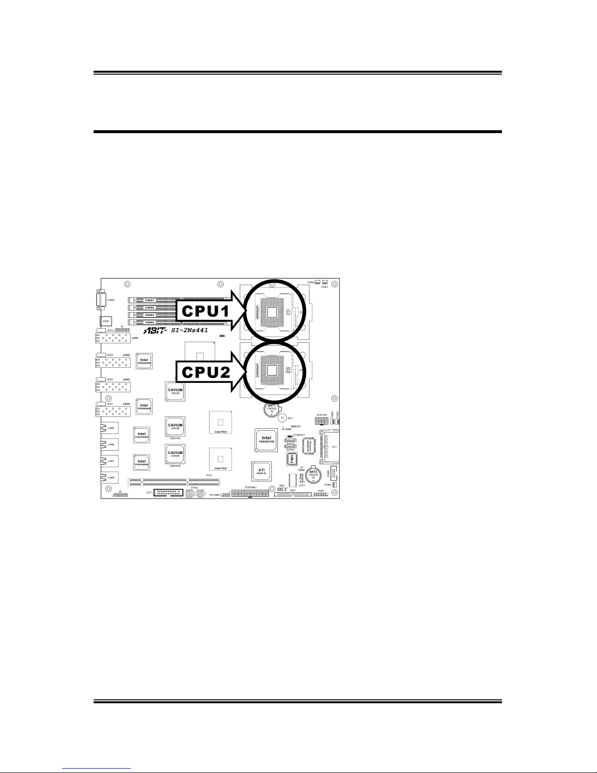
1.2. Layout Diagram...................................................................... 1-3
1.3. Jumpers & Connectors Description........................................ 1-4
Chapter 2. Hardware Setup.............................................. 2-1
2.1. CPU Socket ............................................................................ 2-1
2.2. System Memory ..................................................................... 2-2
2.3. Connectors, Headers, and Switches ....................................... 2-3
2.3.1. EPS Power Connectors .............................................2-3
2.3.2. FAN Connectors ....................................................... 2-4
2.3.3. CMOS Memory Clearing Header............................. 2-5
2.3.4. Front Panel Switches & Indicators Connection
Headers ..................................................................... 2-6
2.3.5. PCI Slot..................................................................... 2-7
2.3.6. Additional USB Port Connection Header................. 2-8
2.3.7. IDE Disk Drive Connector ....................................... 2-9
2.3.8. System Management Bus Connection Header ....... 2-10
2.3.9. Additional COM Port Connection Header ............. 2-11
2.3.10. Connection Header for Parallel Port....................... 2-12
2.3.11. Serial ATA connectors ........................................... 2-13
2.3.12. Low Pin Count Connection Header........................ 2-14
2.3.13. LED Connector for Network Interface................... 2-15
2.3.14. External Keyboard/Mouse Connection Header...... 2-16
2.3.15. Connection Header for VGA Output...................... 2-17
2.3.16. External I/O Panel................................................... 2-18
Chapter 3. BIOS Setup...................................................... 3-1
3.1. Main Menu ............................................................................. 3-2
3.2. Advanced Menu ..................................................................... 3-5
3.2.1. Advanced BIOS Features ......................................... 3-5
User’s Manual

3.2.2. Advanced Chipset Features ...................................... 3-9
3.2.3. Integrated Peripherals ............................................. 3-10
3.2.4. Power Management Setup ...................................... 3-16
3.2.5. PnP/PCI Configurations.......................................... 3-18
3.3. Security Menu ...................................................................... 3-20
3.4. PC Health Menu ................................................................... 3-21
3.5. Clk/Misc. Menu.................................................................... 3-22
3.6. Exit Menu ............................................................................. 3-24
Chapter 4. Driver Installation .......................................... 4-1
Appendix A. How to Get Technical Support ..................... A-1
SI-2Ns44X Series

Introduction 1-1
Chapter 1. Introduction
1.1. Features & Specifications
CPU
• Supports dual IntelXeon (Nocona) FSB 800MHz up to 3.80GHz and
higher
Chipset
• Intel Lindenhurst-VS
• Intel ICH5
• 2x Intel PXH
Networking Security
• SI-2Ns441:
Onboard one Cavium CN-1120 Security Micro Processor supporting
IPSec/SSL (Default)
• SI-2Ns442:
Onboard two Cavium CN-1120 Security Micro Processors supporting
IPSec/SSL (Optional)
• SI-2Ns443:
Onboard three Cavium CN-1120 Security Micro Processors supporting
IPSec/SSL (Optional)
VGA
• Onboard ATi Rage XL PCI interface VGA (8MB SDRAM)
Memory
• Four 240-pin DIMM sockets
• Supports 144-bit wide dual channel DDR II 400 memory
• Up to 16 GB, ECC Registered memory capacity
LAN
• Intel 82546EB dual-port 64-bit Gigabit Ethernet Controllers x4
System BIOS
• Supports Plug-and-Play (PNP)
• Supports Advanced Configuration Power Interface (ACPI)
• Write-Protect Anti-Virus function by AWARD BIOS
• 4MB Flash ROM
User’s Manual

1-2 Chapter 1
Expansion Slot
• 1x PCI-X 64bit/133MHz (3.3V)
Internal I/O Connectors
• 1x 44pin IDE connector
• 2x SATA connectors
• 1x VGA header
• 1x COM port header (COM2)
• 1x USB 2.0 header (Each header support two USB 2.0 devices)
• 1x LPC debug header
• 1x Printer port header
• 1x SM Bus header (For SM Bus and I2C)
• 1x 50-pin IDE interface Compact Flash Type II socket
• 1x PS/2 Keyboard/Mouse header (KM1)
External I/O Connectors
• 1x Dual USB 2.0
• 1x COM port (COM1)
• LAN Ports:
Default: 4x Optical SPF GbE LAN connectors, 4x RJ-45 w/
Transformer and LED single port GbE LAN connectors
Optional: [2x Optical + 6x RJ-45] or [8x RJ-45]
Miscellaneous
• EEB 3.5 form factor (12” x 13”)
• Hardware monitoring – Including Fan speeds, Voltages, System
environment temperature
• Chassis intrusion detector
• 3.3V 64-bit riser card supported (Optional)
All brand names and trademarks are the property of their respective
owners.
Specifications and information contained herein are subject to change
without notice.
SI-2Ns44X Series

Introduction 1-3
1.2. Layout Diagram
User’s Manual

1-4 Chapter 1
1.3. Jumpers & Connectors Description
Jumpers Description Default Setting
CCMOS1 CMOS Memory Clearing Header Pins 1-2 Closed (Normal)
Connectors Description
ATX12V1 8-Pin EPS12V Power Connector
ATXPWR1 24-Pin EPS12V Power Connector
COM2 Connection Header for Additional COM Port
DIMM1~DIMM4 DDR DIMM Slots
FAN1/FAN4 CPU and System Fan Power Connectors for CPU1
FAN2/FAN5 CPU and System Fan Power Connectors for CPU2
FAN3 Auxiliary Fan Power Connector
FPIO1 Front Panel Switch Connection Headers
FP-USB1 Additional USB Port Connection Header
IDE1 IDE Disk Drive Connector (Pitch 2.5)
J6 Connection Header for Case Intrusion Detector
J8/J9 LED Connectors for Network Interface
KM1 External Keyboard/Mouse Connection Header
LPC1 Connection Header for Low Pin Count (Reserved for
internal testing)
LPT1 Connection Header for Parallel Port
PCI1 PCI-X 64bit/133MHz Expansion Slot (3.3V)
SATA1/SATA2 Serial ATA connectors
SMBUS1 System Management Bus Header
VGA1 Connection Header for VGA Output
SI-2Ns44X Series

Hardware Setup 2-1
Chapter 2. Hardware Setup
2.1. CPU Socket
This server board provides dual 604-pin Zero Insertion Force (ZIF) sockets to install
the Intel Xeon CPU. You may install either one or two CPUs, but to set up system
with only one CPU, it MUST be installed in the primary socket (socket “CPU1” in
this model). To install a second processor, you must verify that the second processor
is identical to the first processor with same voltage and speed. Using non-identical
processors could cause system failure.
User’s Manual

2-2 Chapter 2
2.2. System Memory
This server board provides four 240-pin Double Data Rate (DDR) Dual Inline
Memory Module (DIMM) slots for Registered ECC DIMM modules with memory
expansion size up to 16GB.
ATTENTION: Populate the DDR DIMMs in-order and in-pair (of the same type
and size) by starting from DIMM1+DIMM2 to DIMM3+DIMM4.
Single Channel Dual Channel
DIMM1 DIMM2 DIMM3 DIMM4 DIMM1 DIMM2 DIMM3 DIMM4
X X X
X X X X X X
X
X X
SI-2Ns44X Series

Hardware Setup 2-3
2.3. Connectors, Headers, and Switches
All the connectors, headers and switches mentioned here are depending on your
system configuration. Some features you may (or may not) have to connect or to
configure depending on the peripherals you have connected.
WARNING: Always power off the computer and unplug the AC power cord before
adding or removing any peripheral or component. Failing to so may cause severe
damage to your system board and/or peripherals. Plug in the AC power cord only after
you have carefully checked everything.
2.3.1. EPS Power Connectors
These two provides the connection to EPS12V power supply.
User’s Manual

2-4 Chapter 2
2.3.2. FAN Connectors
These connectors each provide power to the cooling fans installed in your system.
The CPU must be kept cool by using a powerful fan with heatsink. The system is
capable of monitoring the speed of the CPU fan.
• FAN1/FAN4: CPU and System Fan Power Connectors for CPU1
• FAN2/FAN5: CPU and System Fan Power Connectors for CPU2
• FAN3: Auxiliary Fan Power Connector
WARNING: These fan connectors are not jumpers. DO NOT place jumper caps on
these connectors.
SI-2Ns44X Series

Hardware Setup 2-5
2.3.3. CMOS Memory Clearing Header
This header uses a jumper cap to clear the CMOS memory.
• Pin 1-2 shorted (default): Normal operation.
• Pin 2-3 shorted: Clear CMOS memory.
ATTENTION: Turn the system power off first (including the +5V standby power)
before clearing the CMOS memory. Failing to do so may cause your system to work
abnormally or malfunction.
User’s Manual

2-6 Chapter 2
2.3.4. Front Panel Switches & Indicators Connection Headers
This header is used for connecting switches and LED indicators on the chassis front
panel.
Watch the power LED pin position and orientation. The mark “+” align to the pin in
the figure below stands for positive polarity for the LED connection. Please pay
attention to connect these headers. A wrong orientation will only cause the LED not
lighting, but a wrong connection of the switches could cause system malfunction.
• HLED (Pin 1, 3): Connects to the HDD LED cable.
• RST (Pin 5, 7): Connects to the Reset Switch cable.
• SPKR (Pin 13, 15, 17, 19): Connects to the System Speaker cable.
• SLED (Pin 2, 4): Connects to the Suspend LED cable.
• PWR (Pin 6, 8): Connects to the Power Switch cable.
• C.O. (Pin 14, 16): Connects to Case Open (Intrusion) device.
• FLED (Pin 18, 20): Connects to the Fault LED cable.
SI-2Ns44X Series

Hardware Setup 2-7
2.3.5. PCI Slot
This slot provides one 64bit/133MHz PCI add-on-card connection (3.3V).
User’s Manual

2-8 Chapter 2
2.3.6. Additional USB Port Connection Header
This header provides two additional USB port connections.
Pin Signal Pin Signal
1 VCC 2 VCC
3 - Data 0 4 - Data 1
5 + Data 0 6 + Data 1
7 GND 8 GND
10 NC
SI-2Ns44X Series

Hardware Setup 2-9
2.3.7. IDE Disk Drive Connector
This connector provides IDE hard drive connection (Pitch 2.5).
User’s Manual

2-10 Chapter 2
2.3.8. System Management Bus Connection Header
This header provides the connection to system management bus (SMBus).
SI-2Ns44X Series

Hardware Setup 2-11
2.3.9. Additional COM Port Connection Header
This header provides one external COM2 port connection.
Pin Signal Pin Signal
1 DCD (Data Carrier
Detect) 2 RXD (Receive-Data)
3 TXD (Transfer-Data) 4 DTR
(Data-Terminal-Ready)
5 GND 6 DSR (Data-Set-Ready)
7 RTS
(Request-to-Send) 8 CTS (Clear-to-Send)
9 RI (Ring-Indicator) 10 VCC (+5V)
User’s Manual

2-12 Chapter 2
2.3.10. Connection Header for Parallel Port
This header provides one external LPT port connection.
Pin Signal Pin Signal
1 STB# 2 AFD#
3 PD0 4 ERR#
5 PD1 6 INIT#
7 PD2 8 SLIN#
9 PD3 10 GND
11 PD4 12 GND
13 PD5 14 GND
15 PD6 16 GND
17 PD7 18 GND
19 ACK# 20 GND
21 BUSY 22 GND
23 PE
25 SLCT 26 VCC
SI-2Ns44X Series
Table of contents
Other Abit Server Board manuals