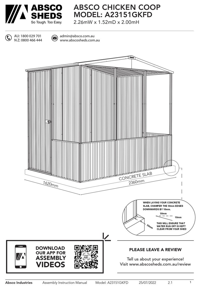
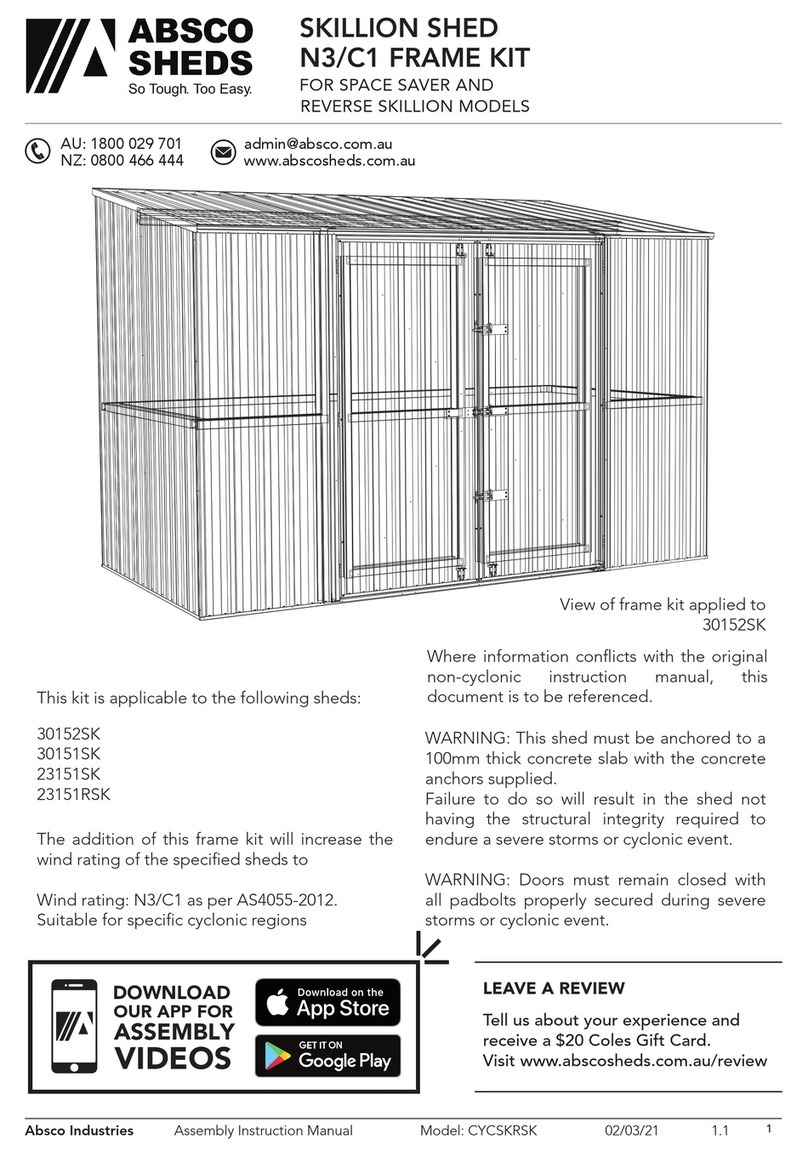
ABSCO SHEDS 30082EK User manual

Absco Industries Assembly Instruction Manual
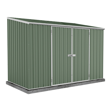
ABSCO EZISLIDER SHED
MODEL: 30082EK
3.00mW x 0.78mD x 1.80mH, 1.95mH
Model: 30082EK 22/11/18 1.1 1
Download the Absco
Sheds Assembly App
for instructional videos
MANU FA CT URED
IN A US TR ALIA
SNAPTiTE
Assemb ly
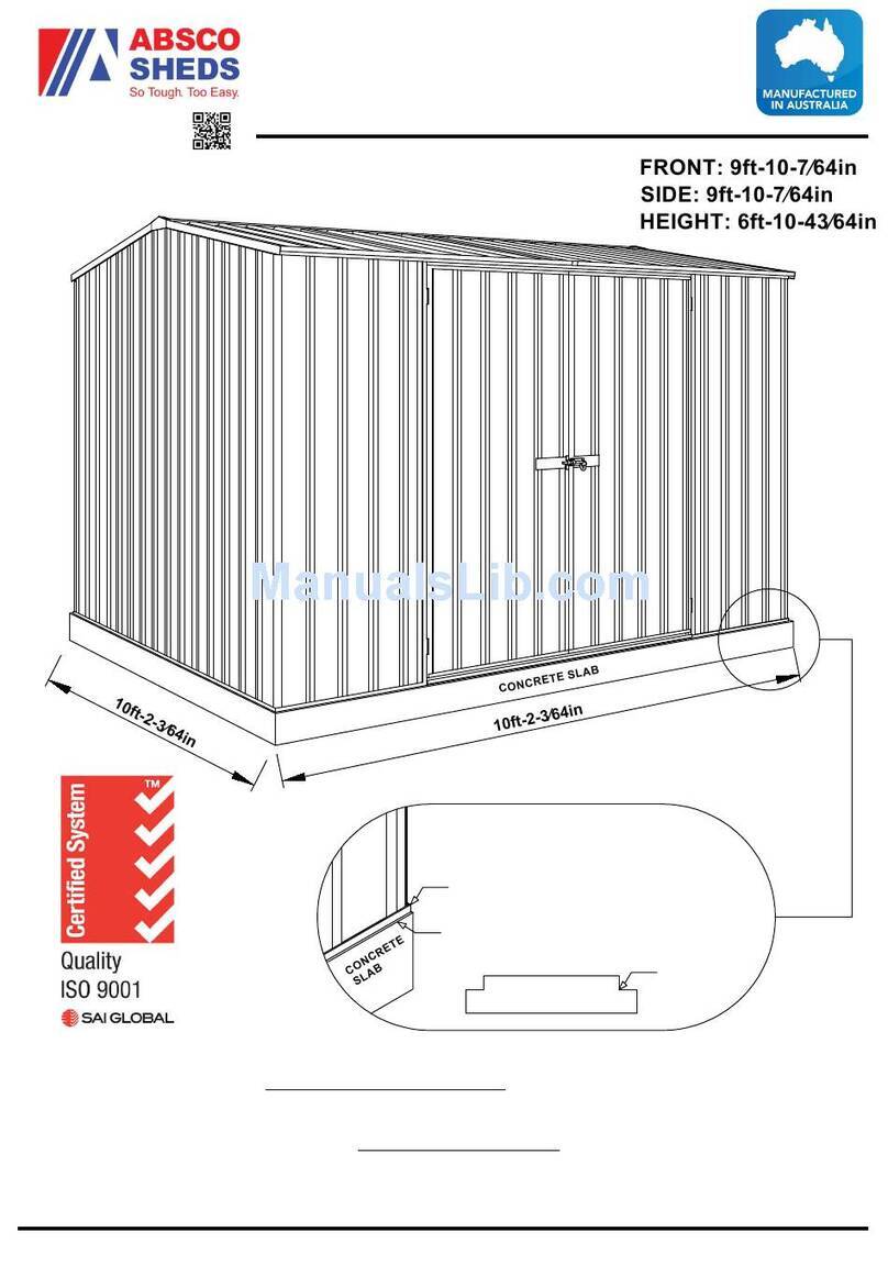
ABSCO INDUSTRIES ASSEMBLY INSTRUCTION MANUAL SHED MODEL: 23151GK 21-11-2017
CONCRETE SLAB
2360mm
1620mm
FRONT: 2.26m
SIDE: 1.52m
HEIGHT: 1.95m
We thank you for choosing an Australian made
shed. For further assistance please visit our detailed
instructional video library at
Http://www.abscosheds.com.au/watch-videos
At ABSCO Industries we are always looking to be
number ONE, so please let us know what you think
of our instructions. Feedback makes us better.
CONCRETE
REBATED EDGE
BOTTOM CHANNEL
CONCRETE SLAB
75mm WIDE REBATE
100mm
WHEN LAYING YOUR CONCRETE
SLAB, ENSURE THERE IS A
REBATED EDGE 25mm DEEP
AROUND THE PERIMETER
THIS WILL HELP WATER EGRESS
FROM THE BASE OF THE SHED
Absco Industries
Premier Shed Model: 23151GK
PAGE 01
When laying concrete slab, ensure there
is a rebated edge 25mm deep around the
perimeter. This will help water egress from
the base of the shed.
AU: 1800 029 701
N Z: 0800 466 444
www.abscosheds.com.au
CONCRETE
SLAB
3100mm
910mm
CONCRETE SLAB: 3100mm X 910mm
50mm
REAR
80mm
FRONT
CONCRETE SLAB
SHED BASE
50mm
50mm
Door opening: 1.44m W x 1.74m H
Roof area: 3.00m x 0.90m
Base area: 3.00m x .0.78m

Absco Industries Assembly Instruction Manual
ABSCO EZISLIDER SHED
MODEL: 30082EK
3.00mW x 0.78mD x 1.80mH, 1.95mH
Model: 30082EK 22/11/18 1.1 2
GENERAL INSTRUCTIONS
• Before commencing any assembly, read through these instructions in detail to gain a thorough
understanding of assembly methods and associated details.
• Unpack the carton and carefully identify and check off all the parts against the parts described
and illustrated on "COMPONENTS PACKING LIST" pages.
SITE PREPARATION
• The site for the shed must be level. An uneven surface may result in misalignment of parts.
• The shed shall be erected on top of a reinforced concrete slab and anchored down appropriately
illustrated on “FINAL CONSTRUCTION” page.
TOOLS REQUIRED
SAFETY NOTES
• Some parts may have sharp edges. It is advisable to wear gloves when handling these items and
safety glasses if drilling holes. Sensible shoes are highly recommended.
• Do not erect your shed in windy conditions.
• Ensure that the shed is securely anchored to a solid foundation immediately after construction is
completed.
• It is highly recommended to erect the shed with two or more people.
RECOMMENDED
3mm drill bit
10mm drill bits
metal & masonry

Absco Industries Assembly Instruction Manual
ABSCO EZISLIDER SHED
MODEL: 30082EK
3.00mW x 0.78mD x 1.80mH, 1.95mH
Model: 30082EK 22/11/18 1.1 3
COMPONENT PACKING LIST
MAIN PACK CARTON (1 OF 1)
CHK CHK
2 4
SNAPTiTE SHEET
STRAIGHT
898x773mm
SH43G
SNAPTiTE SHEET
STRAIGHT
1785x773mm
SH30D
SNAPTiTE SHEET
STRAIGHT
1740x773mm
SH43F
2
2
SNAPTiTE SHEET
STRAIGHT
1915x773mm
SH43B
SNAPTiTE SHEET
STRAIGHT
1915x773mm
SH43C
SNAPTiTE SHEET
LEFT ANGLE
1915x773mm
SHX4L
SNAPTiTE SHEET
RIGHT ANGLE
1915x773mm
SHX4R
2
1
1
INSTRUCTIONS & FITTINGS PACK
INSTP##30082E INSTRUCTIONS & FITTINGS PACK
1INSTP##30082E
2
DOOR
ROLLER OTCO22
CHANNEL
JOINER
200mm LONG
ZACSJ
C-HANDLE
32mm FAST048
M4 x 25mm
PAN HEAD
SCREW
FAST047
38x25mm
DOOR STOP FAST053
PSTKSGL - SINGLE DOOR FITTINGS PACK
1PADBOLT
115mm LONG FAST006 1PADBOLT
HASP FAST007
13mm
DRILL BIT DRILL
1SCREW
PACK 6 PACK6P
1
PHILLIPS HEAD
DRIVER BIT
S2 PH2
FAST038
1
8G x 3/8 SELF
TAPPING SCREWS
x 220
PACK220
PACK6P - SCREW PACK 6
6SBS43E
POP RIVET FAST009 63/16" x 1/2"
COUNTERSUNK
SCREW & NUT
FAST004
FAST005
4
2
2
7
4
1
SBS43E
POP RIVET
x100
PACK13
SINGLE DOOR
FITTINGS PACK PSTKSGL
1
INSTRUCTION
MANUAL IM
1
HAT SECTION
1496.5mm LONG CO95GS
DOOR TRACK
BRACKET
150x150x20mm
BKT260
BRUSH SEAL
SELF ADHESIVE BACKING
3m ROLL
OTCO23
12
QTY QTY
DESCRIPTION DESCRIPTION
PART # PART #

Absco Industries Assembly Instruction Manual
ABSCO EZISLIDER SHED
MODEL: 30082EK
3.00mW x 0.78mD x 1.80mH, 1.95mH
Model: 30082EK 22/11/18 1.1 4
COMPONENT PACKING LIST
Check off all components.
30082ECP CHANNEL SET
CHK CHK
CHANNEL
393mm
STRAIGHT
CH13A
CHANNEL
1496.5mm
NOTCHED
ONE END
CH55BL
CHANNEL
1496.5mm
NOTCHED
ONE END
CH55BR
CHANNEL
1496.5mm
NOTCHED
ONE END
CH55GL
CHANNEL
1496.5mm
NOTCHED
ONE END
CH55GR
CHANNEL
1496.5mm
NOTCHED
ONE END
CH55FL
CHANNEL
1496.5mm
NOTCHED
ONE END
CH55FR
CHANNEL
1496.5mm
STRAIGHT
CH55HL
CHANNEL
1496.5mm
STRAIGHT
CH55HR
CHANNEL
1496.5mm
STRAIGHT
CH81AL
CHANNEL
1496.5mm
STRAIGHT
CH81AR
CHANNEL
1496.5mm
NOTCHED
ONE END
CH81BL
CHANNEL
1496.5mm
NOTCHED
ONE END
CH81BR
CHANNEL
773mm
STRAIGHT
CH58C
CHANNEL
1785mm
NOTCHED
BOTH ENDS
CH80C
CHANNEL
773mm
STRAIGHT
CH81J
CHANNEL
1445mm
STRAIGHT
CH79D
CHANNEL
786mm
STRAIGHT
CH61B
CHANNEL
1740mm
STRAIGHT
CH58L
LIP
898mm LI88K
2 2
2 1
2 2
2
2
1
1
1
1
1
1
1
1
1
1
4
4
QTY QTY
DESCRIPTION DESCRIPTION
PART # PART #

Absco Industries Assembly Instruction Manual
ABSCO EZISLIDER SHED
MODEL: 30082EK
3.00mW x 0.78mD x 1.80mH, 1.95mH
Model: 30082EK 22/11/18 1.1 5
SNAPTiTE ASSEMBLY GUIDE
The Snaptite Assembly System locks end channels to all roof and wall sheets without the need for
tools and fasteners.
To assemble each panel, the perimeter channels are secured to the top and bottom of each panel.
Gently tap the channel over the SNAPTiTE lugs on the sheet, working along the sheet.
Each perimeter channel must finish flush with the edges of the sheets. Simply tap the channel along
the sheets until each end is neatly flush. If you need to remove channels from the panels, slide it off
from the side.
Channel locks the shed panel into
position without the need for screws!
FASTENING SYMBOLS
Secure channel to sheeting by SNAPTiTE
fastening method.
Join components together with one
screw at this location only, as some
channels have extra holes that are not
required for this model of shed.
Do not join components together at
this location yet, as the screws may
obstruct further assembly of the other
components.
Join components together by pre-drill-
ing the holes first. Use one component as
template to mark where the holes are and
drill with a 3mm drill bit.
3mm pop rivet
4mm nut and bolt set.
D
SNAP
T TE
i

Absco Industries Assembly Instruction Manual
ABSCO EZISLIDER SHED
MODEL: 30082EK
3.00mW x 0.78mD x 1.80mH, 1.95mH
Model: 30082EK 22/11/18 1.1 6
Guide on Joining Spliced Channels
The text marked on all parts must be shown on the same side as each other
Step 1.
Position the channels and the
CSJ joiner so the centre of
the CSJ is in line with the end
of each channel to be joiner
together.
Step 2.
Join the first channel to the CSJ
by inserting the centre of the
CSJ, on an angle, to the end of
the channel where the JOIN>>
text is marked.
Push down one side of the CSJ
until you hear a ‘click’.
Step 3.
Join the second channel to the
CSJ by positioning the <<JOIN
of the channel at the centre of
the CSJ, on an angle. Push the
CSJ into the channel until you
hear a ‘click’.
Finished Channel.
The joined channels should
now look like the picture with
the CSJ positioned equally
inside of the joined channels.
Drill out holes with 3mm drill
bit in CSJ to match the holes
in channel and secure with the
screws supplied.
These may have to be
temporarily removed during
assembly.
= =
JOIN>> <<JOIN
CSJ
==
JOIN>>
J
==
JOIN>> SJ
= =
JOIN>>
<<JOIN
= =
JOIN>> <<JOIN
Finished Spliced
Channel
Channel
Push
20mm 15mm
CSJ
.
...

Absco Industries Assembly Instruction Manual
ABSCO EZISLIDER SHED
MODEL: 30082EK
3.00mW x 0.78mD x 1.80mH, 1.95mH
Model: 30082EK 22/11/18 1.1 7
PRE-ASSEMBLY OF SPLICED CHANNELS
NOTE: Some channels may have holes in them - You will
need to redrill holes where CSJ joining channel covers
them.
Join together 14x channel sections using 7x channel joiners (Part CSJ)
NOTE: Channels 55G, 55F, & 55H are best secured together using pop rivets through the 15mm high
(front) edge. This minimizes interference with the sliding doors
=
=
=
=
=
=
1 X 55HR
2 x 81A
1 x 55H
1 x 55B
1 x 55G
1 x 81B
81BR
81BL
55GL
55GR
55BR
55BL
55HR
55HL
81AL
81AR
2 X 81AR
2 X 81AL
1 X 55HL
1 X 55BR
1 X 55BL
1 X 55GR
1 X 55GL
1 X 81BR
1 X 81BL
1 x 55F
55FR
55FL
1 X 55FR
1 X 55FL
=1 x 95G
2 X 95GS
13A
POP RIVETS
FRONT
BACK

Absco Industries Assembly Instruction Manual
ABSCO EZISLIDER SHED
MODEL: 30082EK
3.00mW x 0.78mD x 1.80mH, 1.95mH
Model: 30082EK 22/11/18 1.1 8
WALL AND ROOF COMPONENT OVERVIEW 88K
81A
88K
81A
43G
43G
43G
43G
43B
43C
43C
43B
30D
X4L
30D
X4R
80C
80C
79D
61B
81J
81B
55B
61B
81J
55F
55H
79D
55G
95G
260
58L
58C
260
58L
58C
58C
58L
43F
43F

Absco Industries Assembly Instruction Manual
ABSCO EZISLIDER SHED
MODEL: 30082EK
3.00mW x 0.78mD x 1.80mH, 1.95mH
Model: 30082EK 22/11/18 1.1 9
REAR PANEL ASSEMBLY
1x required
43B
43C
43C
43B
SNAP
T TE
i
SNAP
T TE
i
55B
81B

Absco Industries Assembly Instruction Manual
ABSCO EZISLIDER SHED
MODEL: 30082EK
3.00mW x 0.78mD x 1.80mH, 1.95mH
Model: 30082EK 22/11/18 1.1 10
SIDE PANEL ASSEMBLY
1x Right side panel.
1x Left side panel.
X4L
X4R
SNAP
T TE
i
SNAP
T TE
i
SNAP
T TE
i
SNAP
T TE
i
61B
81J

Absco Industries Assembly Instruction Manual
ABSCO EZISLIDER SHED
MODEL: 30082EK
3.00mW x 0.78mD x 1.80mH, 1.95mH
Model: 30082EK 22/11/18 1.1 11
ROOF PANEL ASSEMBLY
1x required
43G
43G
43G
43G
ONE ROW OF
HOLES THIS END
TWO ROWS OF
HOLES THIS END
SNAP
T
TE
i
81A
88K
81A
88K
SNAP
T
TE
i
SECURE THIS ROW OF
HOLES TO THE REAR
WALL (REFER PAGE 14)
SECURE THIS ROW OF
HOLES TO THE FRONT
SECURE THIS ROW OF HOLES TO
PART 55H. (REFER PAGE 16)
55H
FIT THE SLIDING DOOR TOP RAIL SUPPORT
CHANNEL (55H) TO THE ROOF PANEL AT
PRE-PUNCHED LOCATIONS USING POP
RIVETS AS SHOWN.

Absco Industries Assembly Instruction Manual
ABSCO EZISLIDER SHED
MODEL: 30082EK
3.00mW x 0.78mD x 1.80mH, 1.95mH
Model: 30082EK 22/11/18 1.1 12
FRONT PANEL ASSEMBLY
1x required
SNAP
T TE
i
SNAP
T TE
i
SNAP
T TE
i
SNAP
T TE
i
55F
30D
30D
80C
55G
79D
NOTE: PRE-PUNCHED
EDGE HOLES TO THE
OUTSIDE ENDS OF THE
PANEL.
15mm
FLANGE
20mm FLANGE
NOTE: THERE ARE NO
PRE-DRILLED HOLES
FOR THESE PANELS.
PLEASE PRE-DRILL
BEFORE ASSEMBLY.

Absco Industries Assembly Instruction Manual
ABSCO EZISLIDER SHED
MODEL: 30082EK
3.00mW x 0.78mD x 1.80mH, 1.95mH
Model: 30082EK 22/11/18 1.1 13
DOOR PANEL ASSEMBLY
2x required
NOTE: THERE ARE NO
PRE-DRILLED HOLES
FOR THESE PANELS.
PLEASE PRE-DRILL
BEFORE ASSEMBLY.
SNAP
T TE
i
SNAP
T TE
i
58C43F
58L
58C
58L
261
15mm FLANGE
20mm FLANGE
D
50mm
NOTE: THE LOCATING DISTANCE FOR THE ROLLER
CARRIAGE OF 50mm NEEDS TO BE ACCURATE SO
AS TO ACHIEVE THE DOOR STOPPING DISTANCE OF
97mm AS NOTED ON PAGE 16.
WHEN INSTALLING THE DOORS, USE THIS
SCREW TO ADJUST THE HEIGHT, AND ALSO
LEVEL THE DOORS SO THEY BUTT UP FLUSH TO
EACH OTHER.
WHEEL ASSEMBLY HEIGHT
ADJUSTMENT SCREW
D

Absco Industries Assembly Instruction Manual
ABSCO EZISLIDER SHED
MODEL: 30082EK
3.00mW x 0.78mD x 1.80mH, 1.95mH
Model: 30082EK 22/11/18 1.1 14
DOOR PANEL ASSEMBLY CHECK THAT THE HOLE CENTRE OF EACH DOOR HANDLE IS
32mm AS SHOWN. (SOME DOOR HANDLES MAY DIFFER)
MARK OUT THE HOLE CENTRES HALF WAY UP EACH DOOR. IT IS
IMPORTANT TO USE A GREAT DEAL OF ACCURACY WHEN
MARKING AND DRILLING THESE HOLES.
ENSURE THAT YOU MATCH THE DOORS UP AS A PAIR WHEN
FITTING THE HANDLES.
CAREFULLY DRILL 4mm OR 5/32" HOLES THROUGH BOTH SIDES
OF THE CHANNEL AND SHEET AS SHOWN.
FIT THE DOOR HANDLES USING THE 25mm BOLTS SUPPLIED.
A NORMAL PADLOCK CAN BE
INSERTED THROUGH BOTH
DOOR HANDLES FOR ADDED
SECURITY IF DESIRED.
THE BRUSH PILE STRIP IS USED TO REDUCE NOISE
WHEN SLIDING THE DOORS.
CUT THE ROLL OF BRUSH PILE SUPPLIED INTO FOUR
PIECES ABOUT 750mm LONG.
THE SELF ADHESIVE STRIPS ARE TO BE BONDED TO
THE TOP OF THE DOORS ONLY, ON BOTH SIDES
AS SHOWN.
ENSURE THAT SURFACES TO BE ADHERED TO ARE
CLEAN AND DRY.
PEEL OFF THE BACKING TAPE AND PRESS FIRMLY IN
POSITION FOR A PERMANENT BOND.
PART
262
32mm
4/4mm X 25mm
BOLT
FIT BRUSH PILE:
PART 263
BRUSH PILE
POSITION THE STRIPS TO THE
VERY TOP EDGE OF THE DOOR.

Absco Industries Assembly Instruction Manual
ABSCO EZISLIDER SHED
MODEL: 30082EK
3.00mW x 0.78mD x 1.80mH, 1.95mH
Model: 30082EK 22/11/18 1.1 15
PANEL CONSTRUCTION
NOTE: Take care to ensure that all wall panels are not upside down. The top channels of each panel
are pre-punched for attaching roof sheeting. The base channels are not pre-punched.
Side wall channels fit into the
notched rear wall channels.

Absco Industries Assembly Instruction Manual
ABSCO EZISLIDER SHED
MODEL: 30082EK
3.00mW x 0.78mD x 1.80mH, 1.95mH
Model: 30082EK 22/11/18 1.1 16
FINAL CONSTRUCTION
Each anchor consists of one nut, bolt, M10
dynabolt and steel angle.
Drill a 10mm hole into the wall sheet.
Drill a 10mm hole into the concrete.
Bolt and Nut*
M10 4.6/S
Steel Angle*
35 x 35 x 3
M10 Dynabolt*
* Denotes hot dip galvanised finish
Wall Sheet
Slab
Location of 8
concrete anchors
ANCHORING OF SHED

Absco Industries Assembly Instruction Manual
ABSCO EZISLIDER SHED
MODEL: 30082EK
3.00mW x 0.78mD x 1.80mH, 1.95mH
Model: 30082EK 22/11/18 1.1 17
DOOR TRACK AND TRIM ASSEMBLY
95G
55H
95G
264
THE DISTANCE OF 97mm ALLOWS FOR 3mm
CLEARANCE TO ENSURE THE DOORS BUTT NEATLY
TOGETHER.
THESE ANGLES WILL PREVENT THE DOORS FROM
SLIDING PAST THE CENTRE POINT OF THE DOOR
OPENING, AS EACH DOOR ROLLER CARRIAGE MAKES
CONTACT WITH THE PLASTIC ANGLES.
FIT TWO SMALL PLASTIC ANGLES (PART 264) TO
THE SLIDING DOOR BASE TRACK AS SHOWN WITH
TWO POP RIVETS PER ANGLE.
MARK A LINE 10mm FROM
THE FRONT OF THE SHED
FOR POSITIONING THE
SLIDING DOOR TRACK. (95G)
(NOT TO SCALE)
ROOF
W
A
L
L
S
I
D
E
32mm
1448mm
97mm
1448mm
10mm

Absco Industries Assembly Instruction Manual
ABSCO EZISLIDER SHED
MODEL: 30082EK
3.00mW x 0.78mD x 1.80mH, 1.95mH
Model: 30082EK 22/11/18 1.1 18
DOOR TRACK AND TRIM ASSEMBLY
D
O
O
R
ROOF
55H
LIFT THE DOORS INTO POSITION, WITH THE TOP OF
EACH DOOR LOCATED BETWEEN THE FRONT WALL
AND THE TRACK SUPPORT (55H) FRONT TRIM AS
SHOWN, BEFORE MOVING THE BOTTOM TRACK INTO
POSITION.
SECURE THE SLIDING DOOR
TRACK TO THE SHED WITH THE
CORNER ANGLE BRACKET (260)
260
D
D
DD
THE DOORS SHOULD GLIDE SMOOTHLY
ON THE BOTTOM TRACK AS SHOWN.
REMEMBER TO ADJUST THE BOTTOM ROLLERS
AS NOTED ON PAGE 12, SO BOTH DOORS BUTT
UP NEATLY TOGETHER, BEFORE SECURING THE
TRACK TO THE SHED.

Absco Industries Assembly Instruction Manual
ABSCO EZISLIDER SHED
MODEL: 30082EK
3.00mW x 0.78mD x 1.80mH, 1.95mH
Model: 30082EK 22/11/18 1.1 19
Absco Skillion Roof Shed Notes
• 1.G This instruction manual shall be read in conjunction with other consultants drawings, specifications and
written instructions provided by Absco and/or their representatives.
• 2.G The drawings provided herein are for installation and structural engineering purposes only. If discrepancies
are discovered within the documentation provided, these shall be brought to the attention of Absco and
written approvals obtained prior to commencing the affected section of work.
• 3.G If in doubt ask.
• 4.G Until approvals from the local authorities are obtained, commencement of construction from these
drawings shall not commence.
• 5.G Unless varied by the project specification, all materials and workmanship shall be undertaken in
accordance with the relevant Australian standards and the by-laws and ordinances of the relevant building
authorities.
• 6.G All dimensions indicated in these drawings shall be verified on site by the installation contractor. Scaling
of drawings shall not be undertaken.
• 7.G Prior to commencing works on site, the contractor shall verify the position of all services in the area to
ensure that the construction does not interfere with any of those services.
• 8.G During installation on site the shed structures shall be maintained in a stable condition with no part
becoming overstressed or permanently deformed.
• 9.G In circumstances where the shed has been installed in a manner which is inconsistent with the installation
manual, structural certification shall be void.
• 10.G The structural components detailed within this installation manual have been designed for the following
loads in accordance with AS/NZS1170 based on a Class 10a, Type 2 structure:
• Roof Live Load: 0.25 kPa uniformly distributed or 1.1 kN concentrated as per AS/NZS1170.1
• Wind Load: Classification N2, Non-Cyclonic to AS4055 where Vu = 40 m/s, Vs = 26 m/s
Windward wall Cpe = 0.7
Leeward Wall Cp,e = -0.3 to -0.5 as applicable based on shed geometry
Side Wall Cp,e = -0.5 to -0.65 as applicable based on shed geometry
Roof Cp,e = -0.5 to -1.3 depending on wind direction
6-12 Activity St, Acacia Ridge QLD 4110
PO Box 119, Acacia Ridge QLD 4110
AU: 1800 029 701
N Z: 0800 466 444
www.abscosheds.com.au
General

Absco Industries Assembly Instruction Manual
ABSCO EZISLIDER SHED
MODEL: 30082EK
3.00mW x 0.78mD x 1.80mH, 1.95mH
Model: 30082EK 22/11/18 1.1 20
Absco Skillion Roof Shed Notes
• 1.S All structural steelwork shall have a corrosion protection system applied consistent with AS/NZS 2312-
2002.
• 2.S All structural steelwork detailed within this installation manual shall be minimum Grade 550 for roll formed
sections (including roof and wall sheeting) and Grade 250 for angle sections.
• 3.S All roof, and wall sheeting shall be minimum base metal thickness of 0.3mm
• 4.S All snaptite channels and jambs shall be minimum base metal thickness of 0.42mm
• 5.S All top hats shall be minimum base metal thickness of 1.0mm
• 6.S All screw fasteners shall be Phil Pan Head Zinc Plated #8 x 3/4” (STP0820)
• 7.S All bolt fasteners for anchoring shall be M10 minimum grade 4.6/S
• 8.S Installation of screw fasteners shall generally be undertaken in accordance with the relevant provisions
of AS1562.
Steelwork
• 1.F The supporting slab foundation for the garden shed shall be of a minimum size indicated on the installation
manual. The top surface of the formed slab shall be level and free of any irregularities which would inhibit
the installation of the shed.
• 2.F The structural engineering design for the supporting slab foundation shall be undertaken by a suitably
qualified structural engineer. The design shall consider all relevent provision of AS3600 and AS2870.
• 3.F Between adjacent footings or excavations, the contractor installing the slab foundation shall not exceed
a rise of 1 in a run of 2 in line of slope.
• 4.F Unless approved in writing by the slab foundation engineer, the limits of excavations near existing
footings shall be in accordance with that indicated below.
Supporting Slab and Foundations
The contactor shall undertake investigatory
localised excavations near existing
footings to ascertain their depth prior to
excavating adjacent to them. It is noted that
excavating to a depth below that indicated
above shall not be undertaken without
the written approval from the engineer.
Table of contents
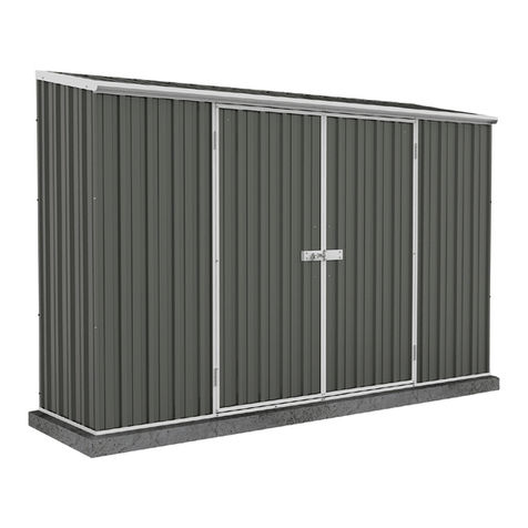
Other ABSCO SHEDS Lawn And Garden Equipment manuals
ABSCO SHEDS
ABSCO SHEDS Highlander Shed 60303HK User manual

ABSCO SHEDS
ABSCO SHEDS J30302G User manual
ABSCO SHEDS
ABSCO SHEDS A23151GKFD User manual

ABSCO SHEDS
ABSCO SHEDS EZISLIM 08081H HIGHSLIM User manual

ABSCO SHEDS
ABSCO SHEDS 30152SECOK Installation guide

ABSCO SHEDS
ABSCO SHEDS 30082SK User manual
ABSCO SHEDS
ABSCO SHEDS 30152SK Installation guide

ABSCO SHEDS
ABSCO SHEDS CYCSKRSK User manual