Absima CR4T Ultimate User manual

Digital proportional radio control system
WARNING:
This product is only for 15 years
old or above
INSTRUCTION
MANUAL
Digital proportional radio control system
© Copyright 2013
Absima GmbH

1
Thank you for purchasing our product, an ideal radio system for beginners or experienced users alike.
Read this manual carefully before operation in order to ensure your safety, and the safety of others or the
safe operation of your system.
If you encounter any problem during use, refer to this manual first. If the problem persists, contact your
local dealer or visit our website for help:
www.absima.com

2
Digital proportional radio control system
Table of Contents
1. Safety .................................................................................................................................................4
1.1 Safety Symbols.................................................................................................................................................. 4
1.2 Safety Guide....................................................................................................................................................... 4
2. Introduction ......................................................................................................................................6
2.1 System Features................................................................................................................................................ 6
2.2 Transmitter Overview...................................................................................................................................... 7
2.2.1 Transmitter Antenna.............................................................................................................................. 7
2.2.2 Wheel and Trigger ................................................................................................................................. 7
2.2.3 Status Indicator....................................................................................................................................... 8
2.2.4 Trims ........................................................................................................................................................... 8
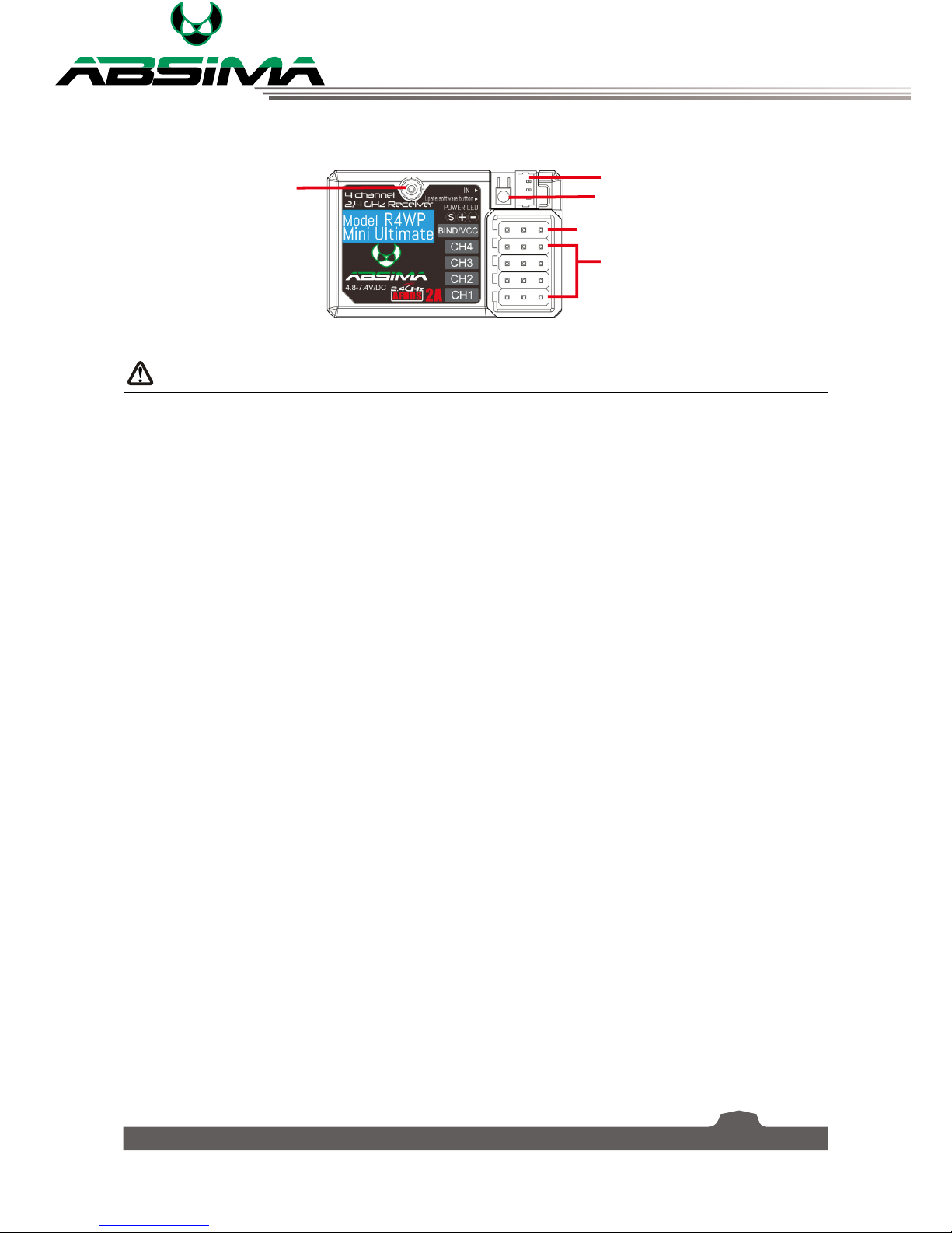
2.3 Receiver Overview .......................................................................................................................................... 9
2.3.1 Receiver Antenna ................................................................................................................................... 9
2.3.2 Status Indicator...................................................................................................................................... 9
2.3.3 Connectors ............................................................................................................................................... 9
2.3.4 USB Simulator Mode ............................................................................................................................ 9
3. Getting Started ...............................................................................................................................10
3.1 Transmitter Battery Installation.................................................................................................................10
3.2 Connecting the Receiver and Servos .....................................................................................................11
4. Operation Instructions...................................................................................................................12
4.1 Power On ..........................................................................................................................................................12
4.2 Binding...............................................................................................................................................................12
4.3 Pre-use Check .................................................................................................................................................12
4.4 Adjusting Wheel Position............................................................................................................................13
4.5 Trims ...................................................................................................................................................................13
4.6 Power Off..........................................................................................................................................................13
5. Home Screen...................................................................................................................................14
6. Function Settings............................................................................................................................15
6.1 Reverse Function............................................................................................................................................15
6.2 End Points Function ......................................................................................................................................15
6.3 Subtrim Function............................................................................................................................................16
6.4 Steering Exponential.....................................................................................................................................17
6.5 Steering Speed................................................................................................................................................18
6.6 Steering Mix.....................................................................................................................................................18
6.7 Throttle Neutral..............................................................................................................................................19
6.8 Throttle Exponential......................................................................................................................................19
6.9 Throttle Curve .................................................................................................................................................20
6.10 A.B.S. ................................................................................................................................................................20
6.11 Throttle Speed..............................................................................................................................................22
6.12 Throttle Middle.............................................................................................................................................22
6.13 Throttle Idel Up............................................................................................................................................23
6.14 Engine Cut......................................................................................................................................................23
6.15 Boat Mode .....................................................................................................................................................24
6.16 Brake Mixing..................................................................................................................................................24

3
6.17 Mixes................................................................................................................................................................25
6.18 Display Servos ..............................................................................................................................................26
6.19 Race Timer .....................................................................................................................................................26
6.20 Keys Function................................................................................................................................................26
6.21 Models.............................................................................................................................................................27
7. RX Setup ..........................................................................................................................................29
7.1 Bind with a receiver.......................................................................................................................................29
7.2 RF std.: ADHDS 2A.........................................................................................................................................29
7.3 RX Battery Monitor........................................................................................................................................29
7.4 Low Signal Alarm ...........................................................................................................................................30
7.5 FailSafe...............................................................................................................................................................30
7.6 Display Sensors...............................................................................................................................................30
7.7 Choose Sensors ..............................................................................................................................................31
7.8 Speed and Distance ......................................................................................................................................31
7.9 Servos Setup....................................................................................................................................................32
7.10 Servos Frequency ........................................................................................................................................32
7.11 Range Test .....................................................................................................................................................32
7.12 Racing Mode.................................................................................................................................................32
7.13 Update Receiver...........................................................................................................................................33
8. System Settings ..............................................................................................................................34
8.1 Blacklight Timeout: (Time)..........................................................................................................................34
8.2 Backlight: (%)...................................................................................................................................................34
8.3 System Sound..................................................................................................................................................34
8.4 Alarm Sound....................................................................................................................................................34
8.5 Auto Power Off ...............................................................................................................................................34
8.6 Screen Calibration..........................................................................................................................................34
8.7 Units....................................................................................................................................................................35
8.8 Language ..........................................................................................................................................................35
8.9 Firmware Update............................................................................................................................................35
8.10 Factory Reset.................................................................................................................................................35
8.11 About CR4TS.................................................................................................................................................35
9. Product Specification ....................................................................................................................36
9.1 Transmitter Specification (CR4T Ultimate) ............................................................................................36
9.2 Receiver Specification (R4WP)...................................................................................................................36
9.3 Sensor Specification......................................................................................................................................37
9.3.1 RPM Speed Module (Magnetic)......................................................................................................37
9.3.2 RPM Speed Module (Optical) .........................................................................................................37
9.3.3 Temperature Acuquisition Module ................................................................................................37
9.3.4 Voltage Acquisition Module.............................................................................................................37
Appendix 1 FCC Statement................................................................................................................38

4
Digital proportional radio control system
1. Safety
1.1 Safety Symbols
Pay close attention to the following symbols and their meanings. Failure to follow these warnings could
cause damage, injury or death.
Danger • Not following these instructions may lead to serious injuries or death.
Warning • Not following these instructions may lead to major injuries.
Attention • Not following these instructions may lead to minor injuries.
1.2 Safety Guide
Prohibited Mandatory
• Do not use the product at night or in bad weather like rain or thunderstorm. It
can cause erratic operation or loss of control.
• Do not use the product when visibility is limited.
• Do not use the product on rain or snow days. Any exposure to moisture (water
or snow) may cause erratic operation or loss of control.
• Interference may cause loss of control. To ensure the safety of you and others,
do not operate in the following places:
• Near any site where other radio control activity may occur
• Near power lines or communication broadcasting antennas
• Near people or roads
• On any pond when passenger boats are present
• Do not use this product when you are tired, uncomfortable, or under the
influence of alcohol or drugs. Doing so may cause serious injury to yourself or
others.
• The 2.4GHz radio band is limited to line of sight. Always keep your model in
sight as a large object can block the RF signal and lead to loss of control.
• Never grip the transmitter antenna during operation. It significantly degrades
signal quality and strength and may cause loss of control.
• Do not touch any part of the model that may generate heat during operation, or
immediately after use. The engine, motor or speed control, may be very hot and
can cause serious burns.

5
• Misuse of this product may lead to serious injury or death. To ensure the safety
of you and your equipment, read this manual and follow the instructions.
• Make sure the product is properly installed in your model. Failure to do so may
result in serious injury.
• Make sure to disconnect the receiver battery before turning off the transmitter.
Failure to do so may lead to unintended operation and cause an accident.
• Ensure that all motors operate in the correct direction. If not, adjust the
direction first.
• Make sure the model flies within a certain distance. Otherwise, it would cause
loss of control.

6
Digital proportional radio control system
2. Introduction
The CR4T Ultimate transmitter and R4WP receiver constitute a 4-channel 2.4GHz AFHDS 2A digital
proportional computerized R/C system. It is compatible with cars and boats.
2.1 System Features
The AFHDS 2A (Automatic Frequency Hopping Digital System Second Generation) developed is specially
developed for all radio control models. Offering superior protection against interference while maintaining
lower power consumption and high reliable receiver sensitivity, AFHDS technology is considered to be
one of the leaders in the RC market today.
Bidirectional Communication
Capable of sending and receiving data, each transmitter is capable of receiving data
from temperature, altitude and many other types of sensors, servo calibration and i-BUS
Support.
Multi-channel Hopping Frequency
This systems bandwidth ranges from 2.4055GHz to 2.475GHz. This band is divided in
140 channels. Each transmitter hops between 16 channels (32 for Japanese and Korean
versions) in order to reduce interference from other transmitters.
Omni-directional Gain Antenna
The high efficiency Omni-directional high gain antenna cuts down on interference, while
using less power and maintaining a strong reliable connection.
Unique ID Recognition System
Each transmitter and receiver has it's own unique ID. Once the transmitter and receiver
have been paired, they will only communicate with each other, preventing other systems
accidentally connecting to or interfering with the systems operation.
Low Power Consumption
The system is built using highly sensitive low power consumption components,
maintaining high receiver sensitivity, while consuming as little as one tenth the power of a
standard FM system, dramatically extending battery life.

7
2.2 Transmitter Overview
1. LCD-Touchscreen-Display
2. TR1 (exponential function
throttle/brake)
3. TR4 (exponential function
steering)
4. TR5 (channel 3)
5. SW1 (channel 3)
6. SW2 (channel 4)
7. POWER (on/off) +
Status Indicator
8. SW3 (A.B.S.)
9. TR3 (trim throttle/brake)
10. Steering wheel
11. TR2 (trim steering)

8
Digital proportional radio control system
12. Micro USB-connection
13. Throttle/brake lever
2.2.1 Transmitter Antenna
Precautions:
• For best signal quality, make sure that the antenna is at about a 90 degree angle to the model. Do not
point the antenna directly at the receiver.
• Never grip the transmitter antenna during operation. It significantly degrades the RF signal quality
and strength and may cause loss of control.
2.2.2 Wheel and Trigger
The CR4T Ultimate has two main control inputs, the wheel and trigger.
• Wheel: Steering, used to control the direction of the model.
• Trigger: Used for acceleration, braking and reverse.
2.2.3 Status Indicator
The status indicator is used to indicate the power and working status of the transmitter.
• Off: the transmitter is powered off.
• Blue light: the transmitter is on and working.
• Flashing: low battery, signal or sensor alarms.
2.2.4 Trims
There are 2 trim switches affecting throttle (TR1), and steering (TR2). Each time a trim is toggled, the
trim will move one step. You can hold the trim in the desired direction to make quicker trim adjustments.
When the trim is changed the system will beep, becoming higher when going up and lower when going
down.

9
2.3 Receiver Overview
2.3.1 Receiver Antenna
Attention • For best signal quality, ensure that the receiver is mounted away from motors
or metal parts.
2.3.2 Status Indicator
The status indicator is used to indicate the power and working status of the receiver.
• Off: the power is not connected.
• Lit in red: the receiver is on and working.
• Flashing quickly: the receiver is binding.
• Flashing slowly: the bound transmitter is off or signal is lost.
2.3.3 Connectors
The connectors are used to connect the parts of model and the receiver.
• CH1 to CH4: used to connect the servos, power or other parts.
• BIND/VCC: used to connect the bind cable for binding, and the power cable during normal operation.
• SERVO: used to connect i-Bus module and extend channels.
• SENS: used to connect all kinds of sensors.
2.3.4 USB Simulator Mode
The system may be used as a HID controller when connected to a computer via USB. When connected
to a computer the function is activated automatically and will be recognized by windows as a game
controller.
To calibrate or test the system in windows:
• 1. Type "RUN" into the search bar and select the program.
• 2. Type "joy.exe" into the "Open:" box and press enter.
• 3. Select the system and open properties within the game controller menu.
• Note: any changes made to trims within the system will take effect in the USB mode. If the system
is not responding as expected, reset to factory settings in the system menu.
CH 1-4
Bind/VCC
Software Update Button
Servo Input Port
Antenna

10
Digital proportional radio control system
3. Getting Started
Before operation, install the battery and connect the system as instructed below.
3.1 Transmitter Battery Installation
Danger • Only use specified battery.
Danger • Do not open, disassemble, or attempt to repair the battery.
Danger • Do not crush/puncture the battery, or short the external contacts.
Danger • Do not expose to excessive heat or liquids.
Danger • Do not drop the battery or expose to strong shocks or vibrations.
Danger • Always store the battery in a cool, dry place.
Danger • Do not use the battery if damaged.
Follow the steps to install the transmitter battery:
1. Open the battery compartment.
2. Insert a fully-charged battery into the compartment. Make sure that the battery makes good contact
with the battery compartment's contacts.
3. Replace the battery compartment cover.

11
3.2 Connecting the Receiver and Servos
Connect the receiver and the servos as indicated below:

12
Digital proportional radio control system
4. Operation Instructions
After setting up, follow the instructions below to operate the system.
4.1 Power On
Follow the steps below to turn on the system:
1. Check the system and make sure that:
• The battery is fully charged and installed properly.
• The receiver is off and correctly installed.
2. Hold the power button until screen lights up.
3. Connect the receiver power supply to the BIND/VCC port on the receiver.
The system is now powerd on. Operate with caution, or serious injury could result.
4.2 Binding
The transmitter and receiver have been pre-bound before delivery. If you are using another transmitter or
receiver, follow the steps below to bind the transmitter and receiver:
1. Turn the transmitter on, press , and swipe from right to left on the screen and then select [RX
Setup].
2. Check the currect [RF std] and receiver type according to the table below. If you need to change the
standard, select [RF std], and [Yes] in the confirmation box, and then the desired standard.
3. Select [Bind with a receiver] and press [Yes] to enter bind mode.
4. Connect the bind cable to the BIND/VCC port of the receiver.
5. Connect the power to any other port. The indicator will start to flash, indicating that the receiver is in
bind mode.
• For [AFHDS 2A 2-way], once binding is complete, the transmitter should exit the bind menu
automaticlly.
• For other protocols, select to exit the bind menu.
6. Remove the bind and power cable from the receiver. Then connect the power cable to the BIND/VCC
port.
7. Check the servos' operation. If anything does not work as expected, restart this procedure from the
beginning.
4.3 Pre-use Check
Before operation, perform the following steps to check the system:
1. Check to make sure that all servos and motors are working as expected.
2. Check operating distance: one operator holds the transmitter, and another one moves the model
away from the transmitter. Check the model and mark the distance from where the model starts to
lose control.
Danger • Stop operation if any abnormal activity is observed.
Danger • Make sure the model does not go out of range.
Attention • Sources of interference may affect signal quality.

13
4.4 Adjusting Wheel Position
The position of the wheel can be adjusted from the right side to the lift side.
1. Use an allen key to remove the allen screws on each side of the controller.
2. Remove the plastic cover from the left side and the wheel from the right.
3. Put the cover and wheel on the opposite side and retighten the screws.
Attention • The max rotation is about 45° . Attempting to push beyond the max rotation
can cause damage to the transmitter.
4.5 Trims
Trims allow you to change the centre point of the steering, throttle, channel 3 and 4. For example, if a
model that always turns slightly left, the steering trim can be used to correct the problem.
The System has 2 groups of trim switches located behind the steering wheel.
4.6 Power Off
Follow the steps below to turn off the system:
1. Disconnect the receiver power.
2. Hold the transmitter's power button to turn off the transmitter.
Danger • Make sure to disconnect the receiver power before turning off the transmitter.
Failure to do so may lead to damage or serious injury.

14
Digital proportional radio control system
5. Home Screen
The home screen diplays useful information about your model, including sensors and function status etc.
1. Receiver signal
2. Profile
3. Radio contorl battery
4. Receiver battery
5. Receiver status
6. Settings
7. Radio control status
8. Help
9. Main menu
The system's navagation is designed to be easy and quick, using both a stylus and fingers.
Icon Function Discription
Main Menu Opens the main menu.
Back Returns to the previous menu.
Activate/Deactivate Acitivate or deactivate the current
function.
Reset Resets the current function to its
default settings.
Help Accesses the onboard help files.
Control Changes values within the current
function.

15
6. Function Settings
6.1 Reverse Function
The Reverse function is used to correct a servo or motor's
direction in relation to the systems controls. For example, if a
steering servo is mounted upside down in order to fit inside a
model, when the system's steering wheel is turned, the servo
will move in the oppisite direction. To fix this, all we need to do
is reverse CH1.
To reverse a channel:
Touch the channel in the list. When reversed, the slider will be at
the [REV].
Select the icon to return to the previous menu.
Select the icon to reset the function.
6.2 End Points Function
Endpoints are the limits of the channels' range of movement. There are two endpoints, one is the low
endpoint and one is the high end point.
To set an endpoint:
1. Move the desired control surface in the direction you
wish to change. The currently selected endpoint will be
highlighted in yellow.
2. Touch the channel you wish to change. The setup menu for
the selected channel displays.
• At the top of the current channel, the selected endpoint
and percentage are shown.
• The endpoints location is shown as a bar and needle.
• The red needle indicates the current setting for the
selected side and channel.
• A real time readout of the channels position can be
seen in this menu as a green bar.
3. Move the wheel at the bottom of the screen left to reduce
the value or right to increase the value.
Select the icon to return to the previous menu.
Select the icon to reset the function.

16
Digital proportional radio control system
6.3 Subtrim Function
Subtrim changes the center point of the channel. For example, if a car's wheels are slightly out of
alignment, the sub trim could be used to fix this.
To set the subtrim function:
1. Select the desired channel from the list. The setup menu for the selected channel displays.
• At the top of the current channel, the selected channel and percentage are shown.
• The center point location is shown as a bar and needle.
• The red needle indicates the current setting for the selected channel.
• A real time readout of the channels position can be seen in this menu as a green bar.
2. Move the wheel at the bottom of the screen left to reduce the value or right to increase the value.
3. Select the icon to return to the previous menu and save.
• To restore default settings of a single channel, select the icon within its subtrim menu.
• To restore the entire function to default, select the icon in the channel selection menu.
Channel List Subtrim setting and channel's current position

17
6.4 Steering Exponential
This function changes the steering channel's response curve. There are 2 main parameters:
• Rate: Changes the outer limits of the steering, the default is 100%. Rate cannot be more than 100%.
• Exp. (Exponential): Changes the steering curve, which changes the response of the steering wheel. The
exp setting can be positive or negative.
Changes to the rate and exponential can be seen on the graph located
in the center of the screen. The system also gives a real-time readout
of the channel's current position.
Note:
The system gives a real time readout of the channels position, not the
wheels position. The wheel will not correlate with the graph if the rate
is under 100% ,or another function like trim has made changes to the
channel's movement and/or outer limit.
By changing the steering curve we can make the wheel more or less
sensitive in different areas of its range of movement, for example,
reducing sensitivity at the middle for more control when making fine
adjustments.
This function must be set as active before use.
To activate the function, make sure that the icon is displayed in the
bottom left corner. If not, press the icon to enable.

18
Digital proportional radio control system
6.5 Steering Speed
This function changes the speed in which the steering travels. If the car's wheels are turning too fast, it
could lead to loss of control. On the other hand, if they do not change position fast enough, the car will
become sluggish and slow to make turns. This function is also used to simulate a realistic for scale models.
There are two variables:
• Turn speed: Sets how quickly the wheels turn from their starting position, to the position the system's
control indicates.
• Return speed: Sets how quickly the wheels turn back to their center position.
To set the steering speed:
1. Select a parameter to change, [Turn speed] or [Return speed].
2. Move the wheel at the bottom of the screen left to reduce the value or right to increase the value.
Select the icon to reset the function.
Select the icon to return to the previous menu.
6.6 Steering Mix
This function changes which wheels are involved in steering, front, rear, or 4 wheel steering. It is set to
[Standard] by default, which means front wheel steering.
If want to change the steering mode, select [Crawler mode]. Note that in crawler mode, CH3 cannot be
controled independently.
To enable this function, select [Crawler mode] from the functions main menu.

19
6.7 Throttle Neutral
This function sets a "dead zone" for their throttle control, which means that the throttle will not function
while still within the dead zone. You can set up the initial amount of throttle that will be applied when the
throttle leaves the dead zone, for driving forward and backward separately.
To set the throttle neutral:
1. Select [Forward], [Dead zone] or [Backward].
2. Move the wheel at the bottom of the screen left to reduce the value or right to increase the value.
Select the icon to reset the function.
Select the icon to return to the previous menu.
6.8 Throttle Exponential
This function has two variables:
• Rate: Reducing the rate shrinks the outer limits of the curve. As the rate drops below 100%, the graph
will update in real-time. The maximum is 100%.
• Exp. (Exponential): Exponential adds curve. It is possible to move to +-100% creating opposite curves.
Select the icon to reset the function.
Select the icon to return to the previous menu.
This function can be toggled using a switch/button, this is assigned in the [Keys function].
Other manuals for CR4T Ultimate
1
Table of contents
Other Absima Control System manuals