Abus AZWG10200 User manual

AZWG10200
Version 1.8.6.6
AZWG10200
ABUS PSTN/IP converter
EN

Preface
Dear Customer,
Thank you for purchasing this PSTN/IP converter. This device is built with state-of-the-art
technology and complies with current domestic and European regulations. Conformity
has been verified, and the CE Declaration of Conformity is available from the
manufacturer on request (www.abus-sc.com).
To guarantee safe operation, it is essential that you observe these installation
instructions.
We want to provide you only with devices that incorporate state-of-the-art technology,
which is why we reserve the right to make technical modifications.
We also reserve the right to make changes to this manual without prior notice.
If you have further questions, please contact your specialist dealer.
Safety information
To avoid the risk of electric shock, never open the device during operation.
No part of the product may be changed or modified in any way; otherwise the device
warranty will be invalidated.
The dialler may only be used within the specified temperature and protection class range.
Using the device outside of the prescribed ranges leads to faster wear and tear and
premature failure. All required information on this can be found in the technical data at
the back of these instructions.
Do not expose the equipment to significant physical stress (knocks, vibrations, etc.)
Incorrect handling and poor transport conditions may damage the device.

3
Contents
Preface............................................................................................................................... 2
Safety information......................................................................................................... 2
Contents ............................................................................................................................ 3
Introduction......................................................................................................................... 5
Information on user manual................................................................................................. 5
Intended use........................................................................................................................ 5
Limitation of liability ............................................................................................................. 5
Safety information............................................................................................................... 6
Explanation of symbols........................................................................................................ 6
Packaging............................................................................................................................ 6
General information ...................................................................................................... 7
Power supply ................................................................................................................... 7
Hardware modules ........................................................................................................ 7
IP Ethernet (LAN)................................................................................................................ 7
IP/GPRS (GSM) .................................................................................................................. 7
A/B converter....................................................................................................................... 7
Alarm transmission............................................................................................................. 7
EN-compliant transmission.................................................................................................. 7
Redundant transmission...................................................................................................... 9
Installation and connection................................................................................................ 9
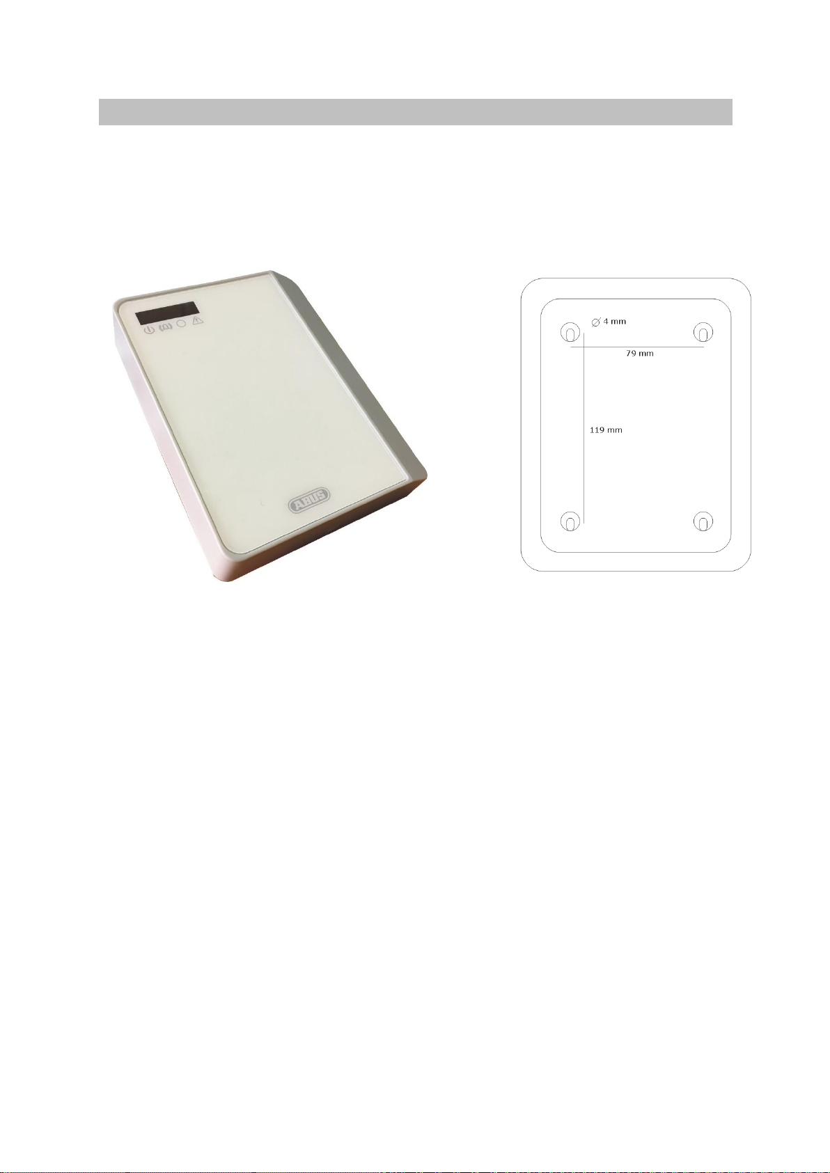
Installation..........................................................................................................................10
Motherboard connections..................................................................................................11
Signal lines.........................................................................................................................12
Outputs...............................................................................................................................12
USB....................................................................................................................................12
Converter connection (POTS).............................................................................................12
SIM card.............................................................................................................................12
LED displays.......................................................................................................................13
Programming with ParamIt+..............................................................................................13
Connecting the AZWG10200-PSTN/IP CONVERTER........................................................15
AZWG10200-PSTN/IP CONVERTER password.................................................................17
Loading a configuration ......................................................................................................17
Importing a configuration from the AZWG10200-PSTN/IP CONVERTER...........................18
Saving a configuration on the PC/laptop.............................................................................18
Saving a configuration on the AZWG10200-PSTN/IP CONVERTER..................................19
Changing a configuration....................................................................................................19
'Modules' tab ......................................................................................................................20
'Transmission' tab...............................................................................................................22
'Encryption' tab...................................................................................................................24
'Notifications' tab.................................................................................................................24

Alarm lines (eight monitored analogue inputs)....................................................25
AUX lines (two digital inputs, high/low)..............................................................26
Test notifications (test and poll notifications)......................................................27
AZWG10200-PSTN/IP CONVERTER system .........................................................28
Outputs...............................................................................................................................29
Diagnosis............................................................................................................................30
Diagnosis > Modules..........................................................................................................31
GSM ..............................................................................................................32
Clock.............................................................................................................32
Ethernet/LAN..................................................................................................32
Converter analogue port ..................................................................................33
Diagnosis > Alarm lines......................................................................................................33
Diagnosis > Outputs...........................................................................................................34
Diagnosis > System............................................................................................................35
Upgrade...............................................................................................................................37
Technical data ....................................................................................................................38
Warranty..............................................................................................................................39
Disposal..............................................................................................................................39
Declaration of conformity..................................................................................................39
Notes...................................................................................................................................40

5
Introduction
Information on user manual
Dear Customer,
Thank you for purchasing this product. This device is built with state-of-the-art
technology.
These instructions contain important installation and operation information. Follow the
directions and instructions in this manual to ensure safe operation. Store this manual
in a safe place for future reference. This manual constitutes part of the device. If you
pass the device on to third parties, please remember to include this manual.
Intended use
Only use the device for the purpose for which it was built and designed. Any other
use is considered unintended.
This product complies with current domestic and European regulations. Conformity
has been proven, and all related certifications are available from the manufacturer on
request.
To ensure this condition is maintained and that safe operation is guaranteed, it is
your obligation to observe this user manual. If you have any questions, please
contact your specialist dealer. Further general information and information on product
support can be found at www.abus.com on the general page or for dealers and
installers, in the Partner portal.
Limitation of liability
Everything possible has been done to ensure that the content of these instructions is
correct. However, neither the author nor ABUS Security-Center GmbH & Co. KG can
be held liable for loss or damage caused by incorrect or improper installation and
operation or failure to observe the safety instructions and warnings. No liability can
be accepted for resulting damage. No part of the product may be changed or
modified in any way. If you do not follow these instructions, your warranty claim
becomes invalid.
Subject to technical modifications.
© ABUS Security-Center GmbH & Co. KG, 07/2016

Safety information
Explanation of symbols
The following symbols are used in this manual and on the device:
Symbol
Signal
word
Meaning
Danger
Indicates a risk of injury or health hazards.
Danger
Indicates a risk of injury or health hazards caused by
electrical voltage.
Importa
nt
Indicates possible damage to the device/accessories.
Note
Indicates important information.
The EU Directive WEEE 2012/19/EC governs the proper
recovery, treatment and recycling of used electronic
devices. This symbol means that, in the interest of
environmental protection, the device must be disposed of
separately from household or industrial waste at the end of
its lifespan in accordance with applicable local legal
guidelines. Used devices can be disposed of at official
recycling centres in your country. Obey local regulations
when disposing of material. Further details on returns (also
for non-EU countries) can be obtained from your local
authority. Separate collection and recycling conserve
natural resources and ensure that all the provisions for
protecting health and the environment are observed when
recycling the product.
Packaging
Danger
Keep packaging material and small parts away from children. There is a
risk of suffocation.
Remove all packaging material before using the device.

7
General information
The AZWG10200-PSTN/IP converter is an IP/GPRS transmission device with two
transmission paths. The transmission device has an LAV interface that is suitable for
open and closed networks and a GPRS module for transmitting to the GSM network.
Depending on the version, the notifications can be imported from the analogue alarm
system either via the signal lines or via the converter.
Power supply
The AZWG10200-PSTN/IP CONVERTER is suitable for supply voltages from 10 to
28 V DC. It uses 70 mA when idle at 12 V DC, 85 mA when communicating via LAN
and 170 mA when communicating via GPRS.
Hardware modules
IP Ethernet (LAN)
The RJ45 Ethernet port on the AZWG10200-PSTN/IP CONVERTER supports
speeds of both 10 Mb/s and 100 Mb/s. The CONVERTER adapts to the network,
with 10 Mb the preferred speed because less power is consumed. Transmissions
can be sent in TCP and UDP.
IP/GPRS (GSM)
The GPRS module can send IP transmission in TCP and UDP. The registration on
the network, the signal strength and IP availability are constantly checked. The
status can be reported to the monitoring station via Ethernet. The ICCID
number of the SIM card can be sent to the monitoring stations with each test
notification, so the card can always be tracked. The antenna can be connected
via an integrated SMA connector.
A/B converter
The AZWG10200-PSTN/IP CONVERTER is equipped with an A/B converter for
analogue SIA, Contact ID and Telim alarm systems in order to link them easily
to the modern IP networks and monitoring stations. The CONVERTER reads the
alarm notifications with Telim, Contact ID or SIA, including text, from the alarm
system, saves them, converts them according to the DC-09 IP protocol and
then checks and sends them to the monitoring station. The analogue Telim
protocol can be converted to VdS 2465 IP and SIA DC-09. All other protocols
are converted from analogue to the same digital protocol, i.e. SIA analogue is
converted to the digital SIA DC-09 protocol and CID analogue to the digital
CID DC-09 protocol.
Alarm transmission
The AZWG10200-PSTN/IP CONVERTER sends the notifications in VdS 2465, Contact
ID DC-09 and SIA DC-09 protocols as needed. VdS 2465 and SIA DC-09 also support
text. The DC-09 protocol is an open, standardised protocol that is supported by many
surveillance services around the world. Depending on use, transmissions can be
encrypted with an AES 128, AES 192 or AES 256 key. VdS 2465 supports encryption
with AES 128.
EN-compliant transmission

The EN 50136-1:2012 standard defines ten transmission methods, six single
transmission paths (SP) and four redundant double transmission paths (DP). The
transmission methods are adjusted according to the different risk classes and
concern the monitoring of the connection, transmission speed, connection
availability and transmission protection. The AZWG10200-PSTN/IP CONVERTER can
be set for all methods and is tested according to the highest SP and DP versions
through EN certification.

9
Redundant transmission
For redundant transmissions, the LAN connection is usually set as the primary
path and the GPRS module as the redundant path. The GPRS module can also
be set as the primary path in the AZWG10200-PSTN/IP CONVERTER. If the
primary path experiences a fault, the redundant path automatically takes over
the monitoring times of the primary path. The most commonly used versions
are listed below.
DP-1 (comparable to class A/B)
oLAN: a test notification is sent from the alarm system via the A/B
converter every 24 hours
oGSM: a test notification is sent from the AZWG10200-PSTN/IP
CONVERTER every 24 hours
DP-3 (comparable to class C)
oLAN: an SIA poll notification is sent every 60 seconds
(monitoring 180 seconds)
oGSM: an SIA poll notification is sent every hour (monitoring
25 hours)
oIf the primary path experiences a fault, the redundant path
automatically takes over the monitoring times of the primary path
and a poll notification is transmitted every 60 seconds
The receiver at the monitoring station monitors the poll notifications and
reports the status and failure.
Installation and connection
The AZWG10200-PSTN/IP CONVERTER is connected to the analogue telephone
connection of the alarm system and/or the alarm lines. The connections comprise the
power supply, Ethernet, GSM antenna (optional), converter (optional) and/or signal
lines, the relay outputs and the tamper contact of the AZWG10200-PSTN/IP
CONVERTER.

Installation
The AZWG10200-PSTN/IP CONVERTER comes in a plastic housing.
Open the housing by loosening the screw on the bottom and then lifting the
cover. There are four installation holes on the back of the housing, which can
be accessed as soon as the printed circuit board (PCB) has been unscrewed.
There are openings on the left and right of the back wall for cable entries.
Observe ESD (electronic static discharge) requirements when coming into
contact with the PCB.

11
Motherboard connections
Ethernet: standard RJ45 CAT5-E connection. Plug the supplied RJ45 cable into the
Ethernet port on the AZWG10200-PSTN/IP CONVERTER and connect it to the DSL
modem/router. An internet connection must be available on the modem/router.
GSM antenna: connect the supplied adhesive-mounted antenna to the SMA GSM
antenna connection on the AZWG10200-PSTN/IP CONVERTER. The real-time display
of the signal strength in the Param-It+ software allows for the antenna position to be
optimised.
10 to 28 V DC supply: the supply can be taken from the danger alarm system. A
DC voltage from 10 to 28 V DC is required.

Signal lines
The motherboard is equipped with eight monitored lines (inputs). These inputs
can be adjusted per line and used as NO (normally open) or NC (normally
closed) contacts. They are monitored with a resistance of 10 K or with two
resistances of 8 K2/15 K (8 K2 idle, 23 K2 when there is an alarm; zero and
open lead to tampering/fault). Separate settings are provided for connection to
Siemens or Bosch fire alarm systems.
Plugs:
L1 C L2 L3 C L4 L5 C L6 L7 C L8
Lx = monitored line (zone)
C = common
D1 = digital line (zone) 1
C = common
D2 = digital line (zone) 2
Outputs
The two relay outputs are marked with OUT1 and OUT2.
OUT1 NO transmission error if an alarm notification is not accepted within
three attempts
OUT2 NC fault with LAN, GPRS communication, supply, start (booting)
OUT1 is active when there is a transmission error. The reset occurs after a
notification is acknowledged. OUT2 can be configured for each connection path.
USB
The USB port has a 5-pin USB mini connection, which is used for programming,
firmware updates and diagnostics.
Converter connection (POTS)
The PSTN converter with the RJ11 port provides the option of connecting an
analogue alarm system with SIA, Contact ID or Telim. The converter is supplied
with a line voltage of 40 V for the dialling tone, Telim, SIA and Contact ID as
well as for evaluation and conversion to VdS 2465 IP or DC-09 IP transmission
protocols. The telephone number and ID number must be set in the alarm
system; see chapter 'Param-It+ programming'.
SIM card
The SIM card must support GPRS (2G) IP data transmission. For redundant use,
1 MB per month is sufficient. The AZWG10200-PSTN/IP CONVERTER supports
multi-roaming SIM cards.

13
LED displays
The AZWG10200-PSTN/IP CONVERTER has the following LEDs:
Green Continuously illuminated: supply OK, device is ready for
operation
FLASHING fast: device is starting (booting)
FLASHING slow: tampering on the signal line/extension
or fault with power supply
Red Continuously illuminated: transmission active
FLASHING fast: 10 second notification acknowledgedby
receiver
FLASHING slow: dialler repetition
Yellow L (1) Continuously illuminated: converter active
Yellow R (2) FLASHING briefly ON –long OFF: Ethernet/LAN fault
FLASHING long ON –briefly OFF: GPRS/GSM fault
Continuously illuminated: Ethernet/LAN and GPRS/GSM
fault
Programming with ParamIt+
All parameters for the AZWG10200-PSTN/IP CONVERTER can be configured
using the ParamIt+ software. ParamIt+ is the software for programming and
troubleshooting the AZWG10200-PSTN/IP CONVERTER and updating its
firmware, both directly via USB connection and via remote configuration.
Install ParamIt+ and start it by double-clicking the icon. The
software is available on the ABUS homepage.
If no users have been created yet, ParamIt+ starts with a standard login
screen.
Press 'OK' or 'Enter' to continue to the start page.


15
Connecting the AZWG10200-PSTN/IP CONVERTER
Port forwarding
Some administrative information can be stored under premises data. The IP
address and port can be entered for remote access to the AZWG10200-
PSTN/IP CONVERTER. Port 64001 is used by default for remote access. The
port number can be changed under Options > Settings > Remote
access/upgrade.
Check whether the AZWG10200-PSTN/IP CONVERTER is supplied with power
and connect the device to the computer/.laptop via the mini USB cable or use
the 'Remote access' option to connect.
The external IP address can be entered for remote access to the AZWG10200-
PSTN/IP CONVERTER.
Remote access progress is displayed on the right-hand side:
ParamIt+automatically detects the AZWG10200-PSTN/IP CONVERTER and
opens the start screen. The product information is displayed along with the
firmware version. The status of the USB or remote connection is indicated at
the bottom left of the screen with a green icon.


17
AZWG10200-PSTN/IP CONVERTER password
If password protection is enabled on the AZWG10200-PSTN/IP CONVERTER,
the login window opens:
If you do not know the password, the device can be reset using the 'Factory
setting' key. ATTENTION! All programming data will be deleted when
this key is pressed!
Separate passwords can be assigned for remote access and the USB (on-site)
connection.
Password required: password required for remote access
Required for USB connection: password also required for connection via USB
A new password can be entered by selecting 'Change password'. The new
password is only active once it has been transmitted from the PC to the
AZWG10200-PSTN/IP CONVERTER by pressing the 'Send' key.
Loading a configuration
Configurations saved on the computer/laptop can easily be loaded.
Press the folder icon at the top left:
A new window opens with the saved files. Select the desired file and press
'Open’. The file is then loaded.

Importing a configuration from the AZWG10200-PSTN/IP CONVERTER
The configuration saved on the AZWG10200-PSTN/IP CONVERTER can easily
be imported using the 'Receive' key.
Press OK.
Press OK again to confirm.
Saving a configuration on the PC/laptop
The newly created or changed programming can be saved by pressing the key
with the diskette icon on it. A new window opens. Enter a file name and press
‘Save’.
The files are saved to the following destination by default: \My
Documents\ParamIt+\Parameters. The save location can be changed in the
save menu. Subfolders can also be created.

19
Saving a configuration on the AZWG10200-PSTN/IP CONVERTER
The newly created or changed programming can be saved on the
AZWG10200-PSTN/IP CONVERTER by pressing the 'Send'key.
Press OK.
Press OK.
Changing a configuration
The configuration of the AZWG10200-PSTN/IP CONVERTER is ideally changed
by working through the tabs from left to right. Many settings are configured
by default.

'Modules' tab
The settings for the GSM, Ethernet (LAN), converter and time server hardware
modules are configured in the 'Modules' tab.
GSM module
ON GSM module enabled for transmission
GPRS enabled for IP transmission
APN: provider access point
User name: GPRS (2G) provider login
Password: GPRS (2G) provider login
PIN code: used if there is a PIN on the SIM card
Ethernet/LAN module
The Ethernet module is the LAN port on the PCB and allows for transmission
via Ethernet.
ON Ethernet/LAN module enabled for transmission and remote
access
Obtain IP address automatically (DHCP)
If this option is ticked, the AZWG10200-PSTN/IP
CONVERTER automatically obtains the network settings
via DHCP
Ethernet/LAN
Enter the desired data for a fixed IP address, gateway
and subnet mask. (If these fields are greyed out, the tick
mark for 'Obtain IP address automatically (DHCP)' must
be removed.)
Smart IP configuration active
If DHCP is not enabled, the 'Smart IP configuration
active' option can be ticked. Then if the entered data
Table of contents
Other Abus Media Converter manuals