AC Infinity CLOUDLINE AC-FKS4 User manual

USER MANUALUSER MANUAL
CLOUDLINE
AIR FILTRATION SYSTEM


3
WELCOME
Thank you for choosing AC Infinity. We are committed to product quality and friendly customer service.
If you have any questions or suggestions, please don’t hesitate to contact us. Visit www.acinfinity.com
and click contact for our contact information.
EMAIL
support@acinfinity.com
WEB
www.acinfinity.com
LOCATION
Los Angeles, CA

4
PRODUCT
Air Filtration System 4
Air Filtration System 6
Air Filtration System 8
MODEL
AC-FKS4
AC-FKS6
AC-FKS8
UPC-A
819137022065
819137021891
819137022072
MANUAL CODE CL2105X1

5
MANUAL INDEX
Manual Index .................................................................................
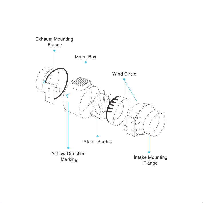
Key Features .................................................................................
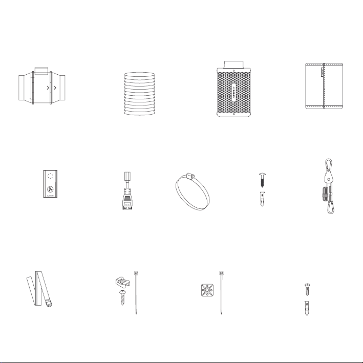
Product Contents ...........................................................................
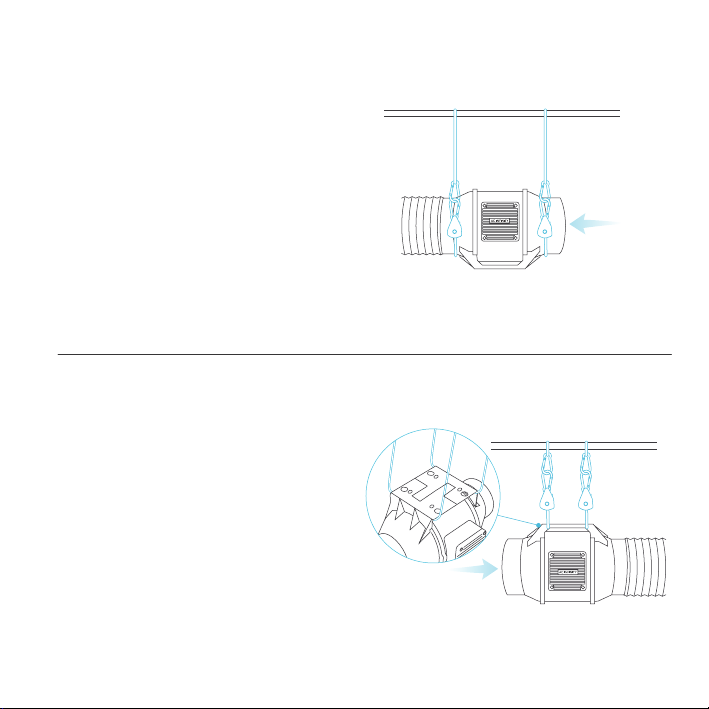
Installation (Hanging) .....................................................................
Installation (Motor Cap Orientation) ...............................................
Installation (Mounting) ...................................................................
Installation (Filter & Ducting) .........................................................
Powering and Setup ......................................................................
Controller Upgrade ........................................................................
Cleaning ........................................................................................
Programming .................................................................................
FAQ ................................................................................................
Other AC Infinity Products .............................................................
Warranty ........................................................................................
Page 5
Page 6
Page 7
Page 9
Page 14
Page 15
Page 20
Page 25
Page 26
Page 27
Page 29
Page 30
Page 32
Page 33

6
KEY FEATURES
SPEED CONTROLLER
Single button controller
with circular dot display that
enables fan speed control in
ten speeds.
DUAL BALL BEARINGS
The motor contains ball
bearings with a 67,000 hour
lifespan. Enables the fan to be
mounted in any orientation.
IP-44 PROTECTION
The inline duct fan is sealed
to Ingress Protection 44
standards, rated with high
resistance to liquids and dust.
ACTIVATED CARBON
Features RC412 1200+ IAV
Australian charcoal with high
adsorption rate to completely
block odor and scrub the air.
FLEXIBLE DUCTING
The outer layer is made of
dual PVC thermoplastic that
protects the aluminum from
cuts and tears.
REVERSIBLE FLANGES
The flanges can be removed
and placed on the opposite ends
to fully utilize the carbon bed
inside.

7
PRODUCT CONTENTS
DUCT FAN
SYSTEM (x1)
SPEED
CONTROLLER (x1)
CARBON
FILTER (x1)
PREFILTER
CLOTH (x2)
FILTER
STRAPS (x2)
DUCT FAN
SCREW SET (x4)
DUCT
CLAMP (x2)
FLEXIBLE
DUCTING (x1)
WOOD SCREWS
(WALL MOUNT) (x1)
ROPE
CLIP (x2)
WIRE
MOUNT (x6)
PROBE
MOUNT (x1)
TYPE-C
ADAPTER (x1)

8
PRODUCT CONTENTS

9
HANGING
INSTALLATION
To use this filter in intake applications, place the filter inside your grow space. Make sure the filter is
connected to your inline duct fan's intake end before completing the installation.
To use this filter in exhaust applications, place the filter outside of your grow space. Make sure the
filter is connected to your inline duct fan's exhaust end before completing the installation.
INTAKE AND EXHAUST
This fan can be used as either an intake fan or an exhaust fan in grow rooms and larger grow tents.
To achieve optimal whole space ventilation, the intake fan or opening - if not using a fan - must be
situated at a bottom corner of your grow space. The exhaust fan must be hung (shown below) or
mounted at the highest opposite corner possible.
Make sure the intake fan’s airflow arrow is pointing towards your grow space and the exhaust fan’s
arrow pointing away from your grow space.

10
INSTALLATION
Hanging Downward
Loop the two rope hangers around a pole and
the fan's bracket.
Clip the carabiners onto each other. Shorten
the loops as needed.
Make sure the fan's airflow arrow is pointing
towards your desired direction.
Hanging Upward
Loop the two rope hangers around a pole and
clip the carabiners onto each other. Shorten the
loops as needed.
Hang the fan by the duct flanges to secure it.
HANGING - ROPE CLIPS

11
INSTALLATION
STEP 1
Loop the strap around the bracket and a pole.
HANGING - STRAPS
STEP 2
Slip the strap through the inner ladder lock slot
from the bottom.

12
INSTALLATION
STEP 3
Route the strap into the outer ladder lock slot
from the top. Adjust the length of the completed
loop as needed.
HANGING - STRAPS
STEP 4
Tuck the loose end through the center gap of the
ladder lock to secure the loop.

13
INSTALLATION
STEP 5(b) - Hanging Upward
To hang the fan right-side up, loop and tighten
the straps, as shown in steps 1-4, around the
pole.
Hang the fan by the duct flanges to secure it.
HANGING - STRAPS
STEP 5(a) - Hanging Downward
Let the fan hang by the pole once the straps are
secure.
Make sure the fan's airflow arrow is pointing
towards your desired direction.

14
INSTALLATION
STEP 1
When hanging the fan downwards, the motor
cap will appear upside down.You may rotate
this motor cap so that it appears right side up.
Unscrew the motor cap using a screwdriver.
MOTOR CAP
STEP 2
Rotate the motor cap to your desired
orientation. Reapply the screws.
Rotating the motor cap will not void your warranty.

15
INSTALLATION
STEP 2
Remove the motor box from the flange bracket.
Remove the wind circle between the motor box
and the intake flange.
STEP 1
Unscrew the bolts from the plastic rings using a
screwdriver.
MOUNTING

16
INSTALLATION
STEP 3
Use the flange bracket to set your desired fan
position. Mark the four mounting holes.
STEP 4
Drill four holes into the marked locations. Make
sure your mounting area is structurally sound
and free from obstruction.
MOUNTING

17
STEP 5
If you are mounting onto anything other than a
wood support or stud, insert the included four
wall anchors into the drilled mounting holes.
You may need to use a hammer to secure them
through the holes.
INSTALLATION
STEP 6
Align the flange bracket’s holes with the wall
anchors. Screw in four wood screws with a
screwdriver or drill to secure the flange bracket.
Make sure its airflow arrow is pointing in your
desired direction.
MOUNTING

18
INSTALLATION
STEP 8
Slide the motor box back into the flange
bracket, making sure its airflow arrow is pointing
in the same direction as the flange bracket’s
arrow. Screw the bolts back into the plastic
rings to secure the motor box to the flange
bracket.
STEP 7
Place the wind circle back into the intake flange.
MOUNTING

19
STEP 9
Use the included duct clamps to secure your
ducting to either end of the duct fan, making
sure there is a tight seal. Tighten the duct
clamps using a flathead screwdriver.
INSTALLATION
MOUNTING

20
INSTALLATION
FILTER & DUCTING
STEP 1
Slip the cloth over the filter to block dust and
other particles from passing through. Make sure
the entire steel mesh is covered by the cloth.
1 2
STEP 2
Connect your duct tube over the filter. Use duct
clamps to secure the connection. You may also
apply ducting tape before using the duct clamps
for even further security.
3
4
Other manuals for CLOUDLINE AC-FKS4
1
This manual suits for next models
5
Table of contents
Other AC Infinity Air Cleaner manuals