Acces I/O products ETH-IIRO-16 Series User manual

10623 Roselle Street, San Diego, CA 92121 •(858) 550-9559 •FAX (858) 550-7322
contactus@accesio.com •www.accesio.com
MODEL ETH-IIRO-16 FAMILY
ETHERNET ISOLATED DIGITAL INPUT /
RELAY OUTPUT MODULES
USER MANUAL
FILE: ETH-IIRO-16.A2b

Manual ETH-IIRO-16
2
Notice
The information in this document is provided for reference only. ACCES does not assume any
liability arising out of the application or use of the information or products described herein. This
document may contain or reference information and products protected by copyrights or patents
and does not convey any license under the patent rights of ACCES, nor the rights of others.
IBM PC, PC/XT, and PC/AT are registered trademarks of the International Business Machines
Corporation.
Printed in USA. Copyright© by ACCES I/O Products Inc, 10623 Roselle Street, San Diego, CA
92121. All rights reserved.
WARNING!!
ALWAYS CONNECT AND DISCONNECT YOUR FIELD CABLING WITH THE
COMPUTER POWER OFF. ALWAYS TURN COMPUTER POWER OFF BEFORE
INSTALLING A CARD. CONNECTING AND DISCONNECTING CABLES, OR
INSTALLING CARDS INTO A SYSTEM WITH THE COMPUTER OR FIELD POWER ON
MAY CAUSE DAMAGE TO THE I/O CARD AND WILL VOID ALL WARRANTIES,
IMPLIED OR EXPRESSED.

Manual ETH-IIRO-16
3
Warranty
Prior to shipment, ACCES equipment is thoroughly inspected and tested to applicable
specifications. However, should equipment failure occur, ACCES assures its customers that prompt
service and support will be available. All equipment originally manufactured by ACCES which is
found to be defective will be repaired or replaced subject to the following considerations.
Terms and Conditions
If a unit is suspected of failure, contact ACCES' Customer Service department. Be prepared to give
the unit model number, serial number, and a description of the failure symptom(s). We may suggest
some simple tests to confirm the failure. We will assign a Return Material Authorization (RMA)
number which must appear on the outer label of the return package. All units/components should
be properly packed for handling and returned with freight prepaid to the ACCES designated Service
Center, and will be returned to the customer's/user's site freight prepaid and invoiced.
Coverage
First Three Years: Returned unit/part will be repaired and/or replaced at ACCES option with no
charge for labor or parts not excluded by warranty. Warranty commences with equipment shipment.
Following Years: Throughout your equipment's lifetime, ACCES stands ready to provide on-site or
in-plant service at reasonable rates similar to those of other manufacturers in the industry.
Equipment Not Manufactured by ACCES
Equipment provided but not manufactured by ACCES is warranted and will be repaired according to
the terms and conditions of the respective equipment manufacturer's warranty.
General
Under this Warranty, liability of ACCES is limited to replacing, repairing or issuing credit (at ACCES
discretion) for any products which are proved to be defective during the warranty period. In no case
is ACCES liable for consequential or special damage arriving from use or misuse of our product.
The customer is responsible for all charges caused by modifications or additions to ACCES
equipment not approved in writing by ACCES or, if in ACCES opinion the equipment has been
subjected to abnormal use. "Abnormal use" for purposes of this warranty is defined as any use to
which the equipment is exposed other than that use specified or intended as evidenced by
purchase or sales representation. Other than the above, no other warranty, expressed or implied,
shall apply to any and all such equipment furnished or sold by ACCES.

Manual ETH-IIRO-16
4
Table of Contents
Chapter 1: Introduction ......................................................................................................5
Features ...........................................................................................................................5
Factory Options...............................................................................................................5
Typical Applications .......................................................................................................5
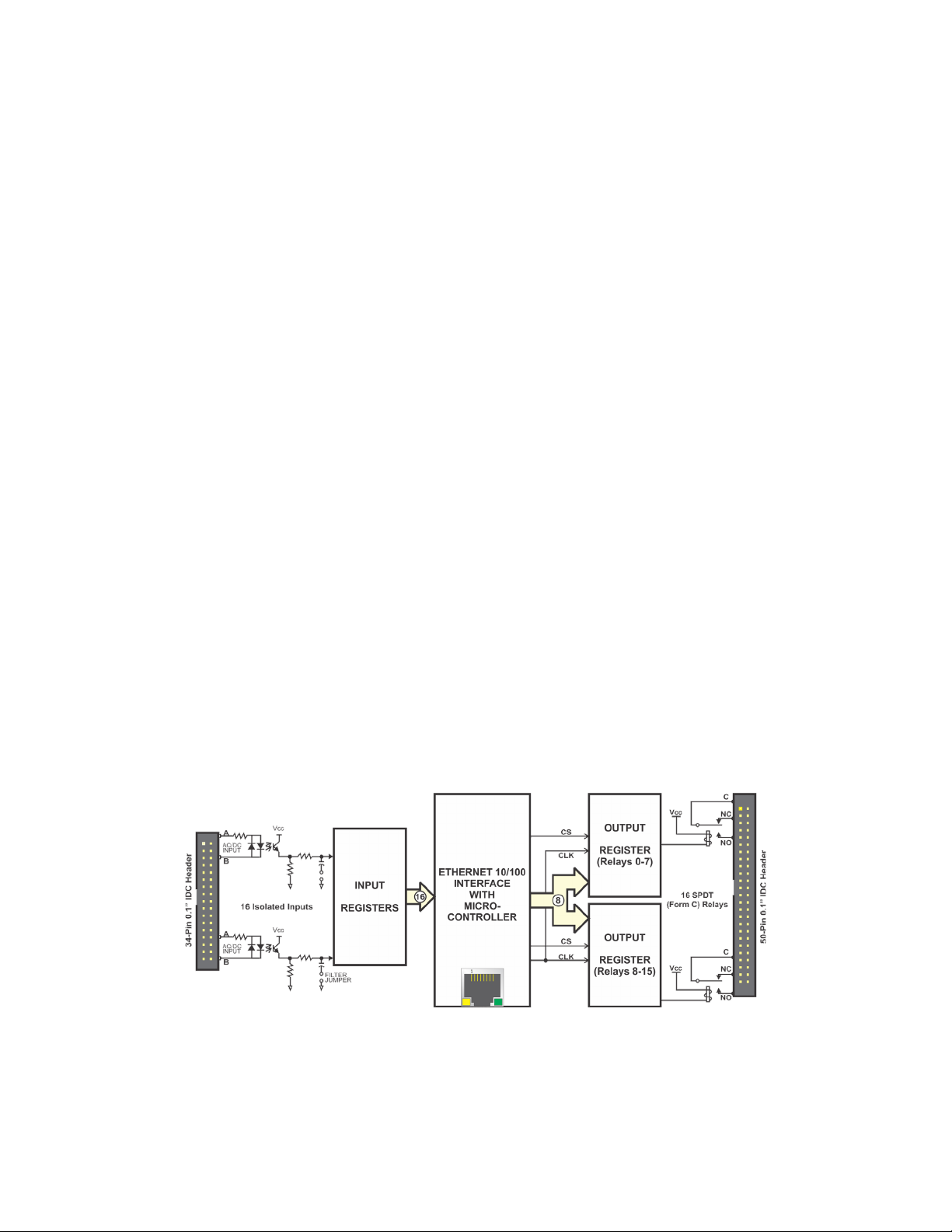
Functional Description ...................................................................................................6
OEM ETH/104 FORM FACTOR .......................................................................................6
Figure 1-1: Block Diagram ..........................................................................................6
Ordering Guide................................................................................................................7
Model Options .................................................................................................................7
Special Order...................................................................................................................7
Included with your board................................................................................................7
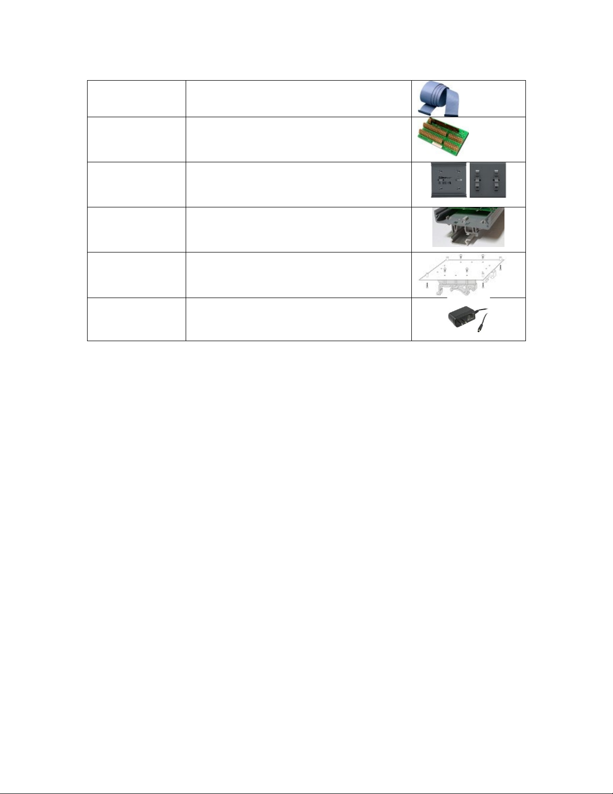
Optional Accessories......................................................................................................8
Chapter 2: Installation ........................................................................................................9
Software Installation .......................................................................................................9
Hardware Installation......................................................................................................9
Chapter 3: Hardware Details ............................................................................................10
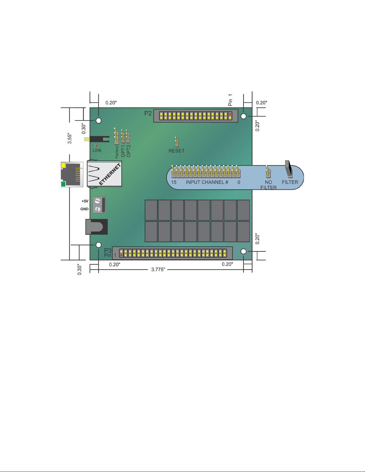
Option Selections..........................................................................................................10
Figure 3-1: ETH-IIRO-16 Option Selection Map .......................................................10
Ethernet Connector.......................................................................................................10
Input Filters....................................................................................................................10
LED .................................................................................................................................10
DC Power Jack ..............................................................................................................10
DC Power Screw Terminals..........................................................................................11
50 and 34 Pin Box Headers ..........................................................................................11
Chapter 4: Ethernet Address Information.......................................................................12
Chapter 5: Programming..................................................................................................13
TCP/IP.............................................................................................................................13
Client API .......................................................................................................................13
AEW_Connect()..........................................................................................................13
AEW_Disconnect().....................................................................................................13
AEW_GetStatus() .......................................................................................................13
AEW_DIO_Configure()...............................................................................................13
AEW_DIO_WriteAll() ..................................................................................................13
AEW_DIO_ReadAll() ..................................................................................................13
Packet Structure............................................................................................................14
Table 5-1: Packet Type Definitions...........................................................................14
Chapter 6: Connector Pin Assignments .........................................................................15
Table 6-1: Connector Pin Assignments ...................................................................15
Table 6-2: Input Connector Signal Names and Descriptions.................................15
Chapter 7: Specifications.................................................................................................16
Customer Comments........................................................................................................17

Manual ETH-IIRO-16
5
Chapter 1: Introduction
Features
•Ethernet 10/100 RJ45 connector for interfacing to CPU or network
•DHCP or static IP assignment
•16 optically isolated inputs (3V to 31V)
•16 Form C electro-mechanical relays switch 1A
•Internal, removable terminal board for easy wiring
•PC/104 module size and mounting compatibility
•Small (4" x 4"x 1.7") rugged industrial enclosure
•DC Jack and screw terminals for external power
Factory Options
•Eight and four input/output versions
•Input only and relay only versions
•Economy “E” version without the screw terminal board
•OEM (board only) version with PC/104 mounting holes and PCB footprint for added
flexibility in embedded applications
•Extended operating temperature (-40˚C to +80˚C)
•Wide input (7Vdc to 30Vdc) external power
•RoHS compliant version
•DIN Rail Mounting provision
Typical Applications
•Automatic Test Systems
•Kiosks
•Laboratory Automation
•Robotics
•Machine Control
•Security Systems, Energy Management
•Relay Monitoring and Control
•Parallel Data Transfer to PC
•Sensing Switch Closures or TTL, DTL, CMOS Logic
•Driving Indicator Lights or Recorders

Manual ETH-IIRO-16
6
Functional Description
The ETH-IIRO-16 Series (4, 8 and 16 channels) is an ideal solution for adding portable,
easy-to-install, isolated input and relay output digital I/O capabilities to any Ethernet
network. It is excellent for controlling external relays, driving indicator lights, fuel pumps,
high voltage control and more. Typical industries are Automotive, Industrial, and Factory
and Home automation.
This unit features 16 Form C (SPDT) electromechanical relays and 16 optically isolated
digital inputs. The isolated, non-polarized inputs may be driven by either DC sources of 3-
31 V (or higher by special order) or AC sources at frequencies of 40 Hz to 10KHZ. Optically
isolating the digital inputs from each other and from the computer, assures smooth, error-
free data transmission in noisy, real-world environments.
The input channels are accessed via a 34-pin IDC type vertical header. The fully protected
isolated outputs are de-energized at power-up to prevent an unintended control output
signal. Data to the solid state outputs are latched and are available via a 50-pin IDC type
vertical header. To simplify field wiring connections, the ETH-IDIO-16 family includes an
internal, removable termination board (ETH-STB-84), that mounts directly to the headers.
The ETH-IIRO-16 is designed to be used in rugged industrial environments but is small
enough to fit nicely onto any desk or testing station. Its board is PC/104 sized (3.550 by
3.775 inches) and ships inside a steel powder-coated enclosure with an anti-skid bottom.
The ETH-IIRO-16 has a DC Jack and screw terminals to connect the required external
power. This power can be provided by our PWR-ACDC-5V, your +5Vdc regulated power
supply, or by ordering the –WI option where you provide from 7 Vdc to 30 Vdc.
OEM ETH/104 FORM FACTOR
The OEM (board only) version is perfect for a variety of embedded applications. What
makes the OEM option unique is that its PCB size and mounting holes match the PC/104
form factor (without the bus connections). The board can be added to any PC/104 type
stack by connecting it to an available 10/100 base T port typically available on embedded
CPU form factors such as EPIC, and PC/104. It can also be installed using standoffs inside
other enclosures or systems.
Figure 1-1: Block Diagram

Manual ETH-IIRO-16
7
Ordering Guide
•ETH-IIRO-16 16 isolated digital inputs and 16 relays in enclosure with breakout board
•ETH-IIRO-8 8 isolated digital inputs and 8 relays in enclosure with breakout board
•ETH-IIRO-4 4 isolated digital inputs and 4 relays in enclosure with breakout board
•ETH-RO-16 16 relays in enclosure with breakout board
•ETH-II-16 16 isolated digital inputs in enclosure with breakout board
Model Options
•-ST Screw Terminal pair for high-retention external power connection
•-WI Wide Input external power from 7 to 30VDC
•-OEM Board only version with no enclosure or external power supply
•-T Extended operating temperature of -40 to +80 ˚C
•-RoHS This product is available in a RoHS compliant version. Please call for specific
pricing then add this suffix to the model number on any purchase orders.
Special Order
Contact factory with your special requirement. Examples of special orders would be
conformal coating, right angle or latching I/O headers etc.
Included with your board
The following components are included with your shipment, depending on options ordered.
Please take the time now to ensure that no items are damaged or missing.
•ETH Module in labeled enclosure with an anti-skid bottom
•Internal removable spring cage terminal board

Manual ETH-IIRO-16
8
Optional Accessories
•CAB50F-6 Six-foot ribbon cable assembly with
50-pin female connectors
•STB-50
Screw terminal board, typically ships
with standoffs but can also mount on
SNAP-TRACK or DIN-SNAP
•DIN-SNAP-6
Six inch length of SNAP-TRACK with
two clips, for mounting one STB-50
screw terminal board on a DIN rail
•DIN-SNAP
One foot length of SNAP-TRACK with
four clips, for mounting up to two STB-50
screw terminal boards on a DIN rail
•MP104-DIN DIN-rail mounting adapter plate for
affixing any ETH/104 module to a DIN-rail
•PWR-ACDC-5V External 5 VDC power supply

Manual ETH-IIRO-16
9
Chapter 2: Installation
Software Installation
The software provided with this board is must be downloaded from the product page at
https://accesio.com/files/packages/ETH-IIRO-16/Install.exe then installed onto your system.
Hardware Installation
The board can be installed on any Ethernet network or even just connected directly to a NIC
in your PC. Installing the Ethernet module is as simple as connecting power, then the
Ethernet cable itself. You'll know it worked if you see the link/activity light on the Ethernet
connector housing light/blink. If you do not see activity, check the other end of the Ethernet
cable to ensure it is plugged into your LAN switch/router/gateway/hub/ or directly into your
PC.
This Ethernet module ships preconfigured at a factory-default MAC and IP Address and
networking configuration (listed in Chapter 4: Addressing). The Settings program allows you
to change the module's networking configuration to match your LAN
requirements. However, in order to use the Settings program you will need a Windows
computer connected to the same subnet as the Ethernet module. (You can modify a
Windows PC's networking configuration temporarily if needed, contact an IT support staffer
if you need assistance with this.) In other operating systems please refer to the ETH API
Doc (.html) for the low-level command packet format for the “ChMC” command.
Any networking configuration changes made via the Settings program will be entered into
the onboard non-volatile memory and used at each power-on or reset in the future, as well
as taking immediate effect.
If necessary you can reset the module to the factory default networking configuration by
briefly shorting the OPT1 jumper position while power is applied. (You may need to open the
device' enclosure to reach the OPT1 jumper).

Manual ETH-IIRO-16
10
Chapter 3: Hardware Details
Option Selections
Refer to the settings program installed with the software package. Also, refer to the Block
Diagram and the Option Selection Map when reading this section of the manual.
Figure 3-1: ETH-IIRO-16 Option Selection Map
Ethernet Connector
The Ethernet Connector is an industry standard RJ45 10/100 Base T type with integrated
transmit / receive LEDs.
Input Filters
Filter jumpers are installed in the shipping configuration, which eliminates response to
transient noise or spikes on the inputs. For faster response to changing inputs, remove the
filter jumpers for the affected channels.
LED
The LED on the front of the enclosure is used to indicate power/activity.
DC Power Jack
The DC jack has a 2.00mm post and is designed to be used with the optional accessory
AC/DC regulated 5V external power supply.

Manual ETH-IIRO-16
11
DC Power Screw Terminals
If a more secure retention method of providing the unit with power is desired, use these
clearly marked screw terminals to connect regulated 5VDC.
50 and 34 Pin Box Headers
These headers have standard 0.100" spacing between pins and are keyed to prevent
improper connections. It can be used with standard IDC type ribbon cables, or the included
spring cage accessory board.

Manual ETH-IIRO-16
12
Chapter 4: Ethernet Address Information
Use the provided AIOETHW.dll driver to access the Ethernet board.
All units are shipped from the factory with an identical default MAC address: 00 08 DC 11 99
77. If you are using more than one device in the same ethernet environment you will need
to change the MAC.
The unit is shipped from the factory with a default static IP address: 192.168.1.174
Most customers will wish to change this IP address and related network configuration. Our
Settings... program can assist with this process in Windows. Refer to the ETH API Doc for
details on the packet-level commands to configure the device in other operating systems.
For your information, the device listens on port 51936 for normal operation, and listens on
51937 for upgrading onboard firmware should it become necessary. Under very rare
circumstances you may need to modify your network settings to allow access to these ports.
The firmware supports at most six simultaneous connections during normal operation.

Manual ETH-IIRO-16
13
Chapter 5: Programming
TCP/IP
This model family is TCP/IP. The source for our Windows DLL is installed with the samples,
into the .\Win32\Driver.SRC\DLL\ directory. The intent is for any language able to send
TCP/IP packets be able to utilize the unit.
Client API
To install the client, simply copy AIOETHW.dll next to the program that will use it, or to the
32-bit system directory.
The general sequence to use it is:
•AEW_Connect() to open a connection.
•AEW_DIO_Configure() to set the initial digital input vs output configuration, and
disable the tristate.
•Repeated I/O calls, using AEW_DIO_WriteAll()/AEW_DIO_Write1(),
AEW_DIO_ReadAll().
•AEW_Disconnect() to close the connection when done.
If the connection fails during operation, a new connection can be swapped in, like this:
•AEW_Disconnect() to close the old connection.
•AEW_Connect() to open a new connection.
•Resume with the I/O calls.
The following is a brief reference of common AIOETHW.dll functions.
AEW_Connect()
AEW_Connect() connects to the specified host device. It returns a client reference (like a
handle) that represents the connection, or zero on a failure.
AEW_Disconnect()
AEW_Disconnect() disconnects a client reference, closing the connection and cleaning up
any memory used. After being passed to AEW_Disconnect(), the client reference is invalid.
AEW_GetStatus()
AEW_GetStatus() reads the device's status block.
AEW_DIO_Configure()
AEW_DIO_Configure() sets the direction of the DIO bytes, writes to all of them, and then
disables the tristate. Writes to input bytes are ignored.
AEW_DIO_WriteAll()
AEW_DIO_WriteAll() writes to all the DIO.
AEW_DIO_ReadAll()
AEW_DIO_ReadAll() reads from all the DIO.
For a complete AIOETHW.dll API reference please refer to the HTML API reference
installed in your software directory.

Manual ETH-IIRO-16
14
Low Level Interface Information
The following information is provided for users who cannot or choose to not use
AIOETHW.dll. This is necessary in non-windows operating systems. For your reference
consider reading the source code for AIOETHW.dll provided with your software install.
More information is available in the HTML API reference installed in your software directory
Packet Structure
A packet is a byte-lengthed string; the first byte is the length(in bytes) of the body. A
packet's body consists of a 4-byte (ASCII) “type” followed zero or more bytes of payload.
A few defined packet types are as follows:
Type
Direction
Meaning
Payload
ChIP
M>S
Change IP
address.
4-byte big-endian IP address. For example, C0 A8 01 AE for
192.168.1.174. Device should reply with W_OK or _Err.
RADI
M>S
Read "all"
DIO data.
No payload defined at this time. Device should reply with R_OK or
_Err.
WADO
M>S
Write "all"
DIO data.
1-byte length of DIO data, then DIO data. For example, 06 01 02
04 08 10 20
to set bit 0 on the first byte of DIO, bit 1 on the next
byte of DIO, etc. up to bit 5 on the last byte of DIO. Device should
reply with W_OK or _Err.
W_OK
S>M
Write
succeeded.
1-byte length of written data. For example, 01 to indicate success
of a 1-byte write.
R_OK
S>M
Read
succeeded.
1-byte length of read data, then read data. For example, 03 42 49
4F to read 42h, 49h, and 4Fh.
_Err
S>M
Transaction
failed.
4-byte little-endian Windows error code. For example, 42 00 00 00
for ERROR_BAD_DEV_TYPE, indicating read from a write
-only
device or vice versa.
Table 5-1: Packet Type Definitions
Refer to the ETH API Doc.html for a complete and detailed packet-level command and control
reference.

Manual ETH-IIRO-16
15
Chapter 6: Connector Pin Assignments
Isolated Inputs Connector Pins
Form C Relay Outputs Connector Pins
Pin
Function
Pin
Function
Pin
Function
Pin
Function
1
Iso In 00 A
2
Iso In 00 B
1
Relay 15-NO
2
Relay 15-C
3
Iso In 01 A
4
Iso In 01 B
3
Relay 15-NC
4
Relay 14-NO
5
Iso In 02 A
6
Iso In 02 B
5
Relay 14-C
6
Relay 14-NC
7
Iso In 03 A
8
Iso In 03 B
7
Relay 13-NO
8
Relay 13-C
9
Iso In 04 A
10
Iso In 04 B
9
Relay 13-NC
10
Relay 12-NO
11
Iso In 05 A
12
Iso In 05 B
11
Relay 12-C
12
Relay 12-NC
13
Iso In 06 A
14
Iso In 06 B
13
Relay 11-NO
14
Relay 11-C
15
Iso In 07 A
16
Iso In 07 B
15
Relay 11-NC
16
Relay 10-NO
17
18
17
Relay 10-C
18
Relay 10-NC
19
Iso In 08 A
20
Iso In 08 B
19
Relay 09-NO
20
Relay 09-C
21
Iso In 09 A
22
Iso In 09 B
21
Relay 09-NC
22
Relay 08-NO
23
Iso In 10 A
24
Iso In 10 B
23
Relay 08-C
24
Relay 08-NC
25
Iso In 11 A
26
Iso In 11 B
25
26
27
Iso In 12 A
28
Iso In 12 B
27
Relay 07-NC
28
Relay 07-C
29
Iso In 13 A
30
Iso In 13 B
29
Relay 07-NO
30
Relay 06-NC
31
Iso In 14 A
32
Iso In 14 B
31
Relay 06-C
32
Relay 06-NO
33
Iso In 15 A
34
Iso In 15 B
33
Relay 05-NC
34
Relay 05-C
35
Relay 05-NO
36
Relay 04-NC
37
Relay 04-C
38
Relay 04-NO
39
Relay 03-NC
40
Relay 03-C
41
Relay 03-NO
42
Relay 02-NC
43
Relay 02-C
44
Relay 02-NO
45
Relay 01-NC
46
Relay 01-C
47
Relay 01-NO
48
Relay 00-NC
49
Relay 00-C
50
Relay 00-NO
Table 6-1: Connector Pin Assignments
Signal Name
I/O
Signal Description Name
Iso In xx A
Iso In xx B
In
Isolated digital input pins, non-polarity sensitive, connect a powered
signal across these pins to read an active input
Table 6-2: Input Connector Signal Names and Descriptions

Manual ETH-IIRO-16
16
Chapter 7: Specifications
ISOLATED INPUTS
Number of inputs: Sixteen
Type: Non-polarized, optically isolated from each other and from the
computer (CMOS compatible)
Voltage Range: 3 to 31 DC or AC Rms (40 to 10000 Hz)
Isolation: 500V*(see note) channel-to-ground or channel-to channel
Input Resistance: 1.8K ohms in series with opto coupler
Filter Response Times: Rise Time = 4.7 mS / Fall Time = 4.7 mS
Non-Filter Response: Rise Time = 10 uS / Fall Time = 30 uS
RELAY OUTPUTS
Number of outputs: Sixteen SPDT form C
Contact Type: Single crossbar; Ag with Au clad
Rated Load AC: 0.5 A at 125 VAC (62.5 VA max.)
Rated Load DC: 1A at 24 VDC (30 W max.)
Max. Switching Voltage: 125 VAC, 60 VDC
Max. Switching Current: 1 A
Contact Resistance: 100 mΩ max.
Contact Life: mech'l: 5 million operations min.
Operating & Release: 5 milliseconds max.
POWER REQUIRED
5V@ 300mA typical (all relays OFF, add 30mA per relay)
5V@ 780mA typical (all relays ON)
Bus Type Ethernet 10/100 Base T, Auto-detecting 1.5kV Isolation
Environmental
Operating Temp.: 0˚C to 70˚C (Extended Temp version operates from -40˚C to +80˚C)
Storage Temp.: -40˚C to +85˚C
Humidity: 5%-90% RH, non-condensing
Mechanical
Board Dimension: 3.550 x 3.775 inches
Box Dimension: 4.00 x 4.00 x 1.7 inches
DC power jack: 2.0mm positive center post (for use with AC/DC converters, or “wall warts”)
DC power screw terminals available via enclosure cutout

Manual ETH-IIRO-16
17
Customer Comments
If you experience any problems with this manual or just want to give us some feedback,
with manual updates.
10623 Roselle Street, San Diego CA 92121
Tel. (858)550-9559 FAX (858)550-7322
www.accesio.com
This manual suits for next models
5
Table of contents
Other Acces I/O products Control Unit manuals