Access MONTANA User manual

VERSION 1.0
MONTANA
INSTALLATION MANUAL
JUMP STRAIGHT TO OUR
QUICK VIDEO GUIDE TO
FITTING A POWERED
WALK IN BATH:

2MONTANA INSTALLATION MANUAL
MONTANA – POWERED SEAT WALK IN BATH
KEY INFORMATION
Maximum user weight: 26 stone / 165kg
Water Capacity: 220ltr
Approximate Bath weight (empty): 84kg
Power Supply: Mains 230V to be supplied via 30mA RCD
Operating Voltage: 24V
Fuse Spur: 5 Amp IP65 rated Non-Switched Fused Spur
Battery backup: Yes
BioCote®antimicrobial additive as standard, proven effective against
inuenza H1N1, E. coli, Salmonella and CRO, CRE, VRE and MRSA
Left hand example (handing of a bath is indicated from which the side the door is when seated in the bath).
Both 1700 and 1500 length bath sizes are annotated on the above diagram.
1675/1500
340230
185
555
460
360
575
700
664
540
1520/1345
1675/1500
340230
185
555
460
360
575
700
664
540
1520/1345
1675/1500
340230
185
555
460
360
575
700
664
540
1520/1345

3MONTANA INSTALLATION MANUAL
CONTENTS
PREPARATION OF SITE��������������������������������������������������������������������������������������������������������������4
BATH FITTING����������������������������������������������������������������������������������������������������������������������������������6
PLUMBING�������������������������������������������������������������������������������������������������������������������������������������������7
PANELS���������������������������������������������������������������������������������������������������������������������������������������������������8
ELECTRICAL WORK�������������������������������������������������������������������������������������������������������������������10
BATTERY BACK UP����������������������������������������������������������������������������������������������������������������������10
HANDSET FITTING���������������������������������������������������������������������������������������������������������������������11
TESTING����������������������������������������������������������������������������������������������������������������������������������������������12
CLEANING AND REPAIR ��������������������������������������������������������������������������������������������������������12
ADDITIONAL INFORMATION��������������������������������������������������������������������������������������������13

4MONTANA INSTALLATION MANUAL
PREPARATION OF SITE
1Carefully remove all packaging and inspect bath
and panels thoroughly�
NOTE Do not use sharp knives or instruments
to remove packaging around the nished
surface areas of the bath.
2Check all component parts are present before
proceeding to remove any existing facilities,
this can be cross checked against the parts
list supplied�
3Remove any existing equipment and materials
as necessary to prepare the site� Check that
the site is clean and free of debris�
4 PreparetheoorareaandensureitisFL AT,
LEVEL AND STRUCTURALLY SOUND�
Check walls are square�
5You may want to remove the door or seat
to make is easier to install�
The bath door can be removed by simply lifting
carefully� Do not unscrew the hinges from either
the door or bath�
To remove the seat, the bath will need to be
pluggedinandhandsetttedtodoso,see
PAGES 10 and 11 for guidance�
Use the handset to move the seat to its halfway
position, carefully push in the two rear chrome
buttons and lift the seat off starting at the head
end of the bath� See FIGS. 1 and 2�
This unit is heavy – minimum of two
people are required to move it. Please
ensure the bath is carried only by the
frame or ange. Please read through
carefully before commencing any work.
KG
FIG. 1
FIG. 2

5MONTANA INSTALLATION MANUAL
SOFT SEAT OPTION
The material seat available on the bath provides
a softer alternative to the solid option� The soft
seat enables you to sit on the bottom of the bath
maximising your bathing space and comfort�
Fitting the soft seat is very similar to the standard
solid seat�
1Use the handset to move the seat to its
halfway position�
2Ensure the fabric is the correct way on the
shrouds (covering them)
3Locate the shroud onto the yoke assembly
ensuring they are the correct way around
lining up the lock button and yoke hole�
4 Depressthebuttonsandttheshroudover
to lock it in place� Reverse steps to remove�
See FIG. 3�
PREPARATION OF SITE
FIG. 3

6MONTANA INSTALLATION MANUAL
BATH FITTING
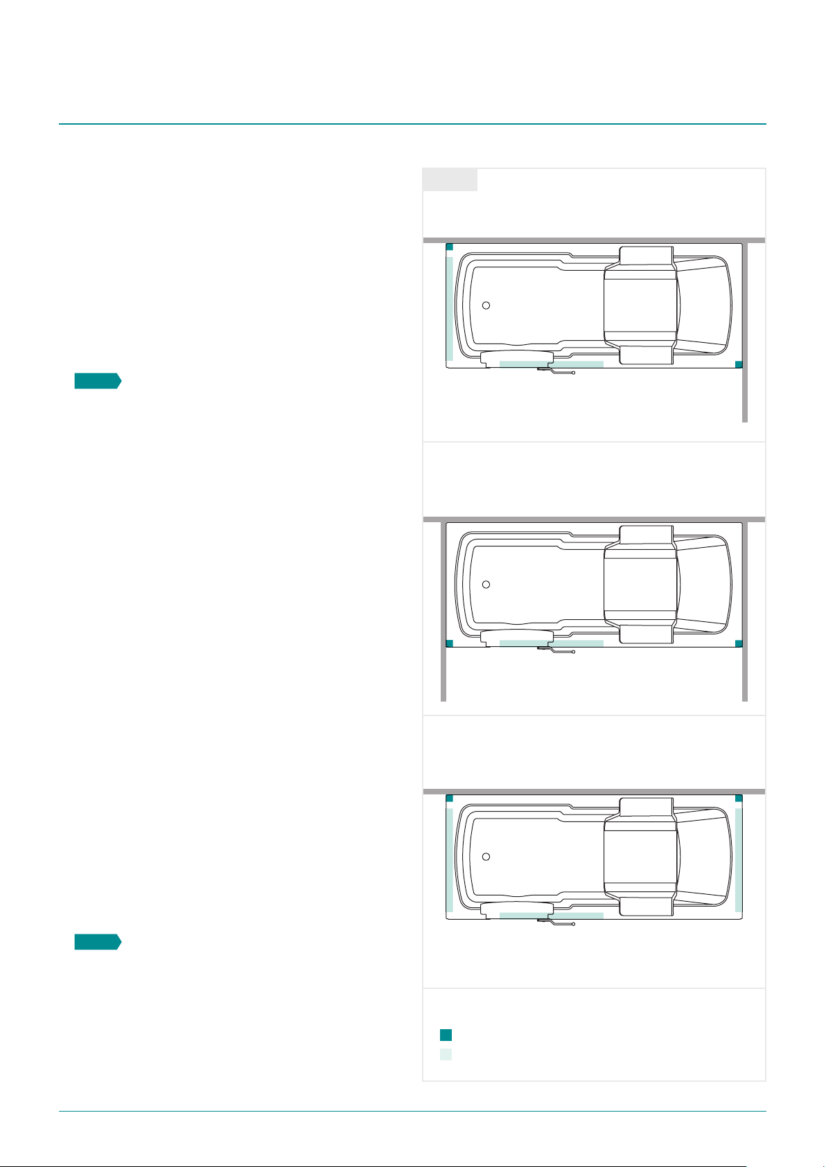
1 Beforethebathisinitsnalpositionidentifythe
best position for the taps, mark and drill the bath as
needed.Installthewasteandoverowtothebath.
2 Remove and dispose of the wooden
transportation board/pallet but KEEP THE FOUR
SLOTTED FOOT BRACKETS� See FIG. 4�
NOTE It is imperative the bath is correctly
level in all planes, as any distortion will cause
the seal around the door to leak.
3 Offer bath to required position and place into
exact position� Level using the feet situated in
each bath corner only� Place the rear slotted
foot brackets with the slots positioned so that
the bath may be slid out of position and the
foot mounting brackets left in place�
NOTE Ensure the slot in the bracket is facing out.
4 Markxingcentresforthebrackets,removethe
bath leaving brackets in place� Fix rear slotted
feetbracketssecurelytotheoor.See FIG. 5�
5 Slide the bath back into position and adjust the
four corner feet to level the bath� Do this by
loosening the top locking nuts beneath the
frame, then use the bottom nuts to adjust the
height until the bath is level� Tighten the top
locking nuts into place once again� Offer up the
footbracketstothefrontfeetandxsecurely
totheoor,lockingthemiddlenuttothefoot
brackets to secure bath� See FIG. 6�
6 Secure the two support feet by loosening the
top nuts, lower the feet until they are sitting
ontheoorandtakingtheweightofthebath.
Once in position lock off the two top nuts�
Check the bath is level and ensure that
the weight is evenly carried.
Transport
board/pallet
Slotted foot
bracket
Wall
FIG. 4
FIG. 5
FIG. 6
Slotted feet brackets
Support feet

7MONTANA INSTALLATION MANUAL
PLUMBING
Ensure that the appropriate
Water By-Laws are followed.
1 Thepipeworkshouldbettedwithisolators.
2Fit the appropriate plumbing and waste
pipework into place allowing, where possible,
the steepest and shortest fall-away to assist in
draining the bath�
3The drainage is to be via a standard 1½” waste
and trap�
4Plumb the taps in, connect and test�
5We strongly recommend installing a TMV
thermostatic mixing valve (FIG. 7), this ensures
a safe water temperature is maintained by
mixing hot and cold�
6 EnsuretheTMVisttedinanaccessible
position suitable for easy maintenance and
adjustment� Take a ‘Tee’ off the cold supply
before it goes into the thermostatic valve
and run this to the cold tap� This allows the
customer to draw cold water into the bath�
7We recommend that the valve be set to 43°C
setting in most cases�This allows the customer
to have a hot bath if they wish – with no fear of
scalding – but also allows them to cool the bath
with cold water by operating the cold tap as
required�
NOTE Discuss this with the customer before
setting the valve to conrm their preference.
1. Run a 22mm
hot feed into ‘H’
2. Run a 22mm
cold feed into ‘C’
MIXED
SUPPLY
HOT
SUPPLY
COLD
SUPPLY
FIG. 7

8MONTANA INSTALLATION MANUAL
Wall
Seat
AB
1The panels need to be held in place using
wallandoorbattens,theconguration
required depends on the installation of the
bath� See FIG. 8 for corner, alcove and straight
wall examples� Batten sizes below:
Wall battens approx. 50 x 50 x 400mm
Front panel battens approx. 50 x 50 x 1000mm
End panel battens approx. 50 x 50 x 500mm
NOTE Battens are not supplied with the bath.
2 Beforethebattensandpanelsarettedthe
bathshouldbelledwithwatertotheoverow
to ensure that the maximum downward
pressure is exerted on the bath� It is preferable
totthepanelswhenthebathisfullofwater
toensurecorrecttrimandt.
We also suggest a bead of silicone sealant is
offered to the lip of the bath now to ensure
awatertightnishbetweenthewallandthe
bath� Leave the water in the bath for as long
as possible allowing the silicone to cure (FIG. 9)�
3Mark out positioning of the panel support
battens for the wall�
Do this by lining them up directly under the
corners marked (A) and (B) as advised on FIG. 8�
Next,drillandxthefrontandendoor
battens as appropriate� Using a spirit level
against the lip of the bath, obtain a vertical angle
andmarktheoortoallowbattenstobexed
totheoorforthepanelstoxagainst.
NOTE The battens should be xed 8mm
in from the vertical edge.
PANELS
KEY:
Vertical wall battens
Horizontal oor battens
Wall
Seat
A
B
FIG. 8
2 x wall battens, 1 x end panel batten,
1 x front panel batten
CORNER
A B
Wall
Seat
2 x wall battens, 1 x front panel batten
ALCOVE
2 x wall battens, 2 x end panel battens
1 x front panel batten
STRAIGHT

9MONTANA INSTALLATION MANUAL
4Offer the panels up and trim to suit, panels can
alsobetrimmedtoaccommodateunevenoor
or wall covering�
Push the panels into place using the metal
springclipsttedtothebathtoholdthem
intoposition.Ifanendpanelistteddrillto
accept two screws to hold the panel against the
wall batten�
DO NOT silicone the panels into place.
These may need to be removed for
access in future.
FIG. 9
PANELS

10 MONTANA INSTALLATION MANUAL
ELECTRICAL WORK
All electrical work must comply
current regulations and should only
be carried out by a qualied electrician.
1The electrical supply should be fed via the
mains through an RCD to 5 Amp IP65 rated
Non-Switched Fused Spur where the power
cable (supplied with the bath) is hard-wired
connected� The control box and battery
are located on the end frame of the bath, see
FIG. 10� A pre-wired lead is supplied and this
The second spur is required to ensure the bath
will continue to operate should there be a fault
intheaccessorytted.
HANDSET
See info on PAG E 11�
EARTH BONDING
Earth bonding and cross bonding is mandatory
for this appliance� This should carried out by a
qualiedelectrician.EarthBondingandCross
Bondingaretobettedandtestedforcontinuity
inaccordancewithIEEregulations.Trailingex
should be protected by conduit when IP box is
situated outside of the bath panels�
BATTERY BACK-UP
In the event of a power-cut the seat is protected
by Battery Back-up�
As the battery back-up begins to lose power, an
audible beep will be heard each time the ‘seat
down’ button is pressed�
SE AT
In battery back-up mode the seat will still operate
but at half speed� In this event we strongly
recommend that you raise the seat and exit the
bath at your earliest convenience�
should be run to the mains supply�
2The mains lead should be left long enough so
that the control box can be removed if servicing
is required�
NOTE We advise the electrical non-switched
fuse spur is accessible so the property owner
can isolate the unit if required (i.e. not behind
panels or boxed in).
ACCESSORIES / OPTIONS
Whereoptionsaretted(i.e.spa,lightsetc.)
a 13 Amp IP65 rated non-switched fused spur
is also required�
230 V
AC
FIG. 10

11MONTANA INSTALLATION MANUAL
HANDSET FITTING
FITTING THE HANDSET PLUG
1 Firstly, locate the handset input port on the
bath (FIG. 11)� The port is already drilled
andttedandcanbelocatedintheupper
front panel or front shell rim near the seat�
The handset plugs in here�
2 Now, taking care to ensure the slot on the plug
matches up correctly with the plug port tab,
gently push into place until properly seated
(FIG. 11)�
RETAINING CLIP INSTALLATION
3 Now that the plug is properly seated, take the
retaining clip and place over the plug as shown
(FIG. 12)�
NOTE Make sure that the tabs on the
retaining clip are facing the bath.
4 Compress the retaining clip slightly and press
into port hole� Manoeuvre the retaining clip
until the tabs on the retaining clip engage with
the retaining clip slots in the port (FIG. 13)�
NOTE There is a raised barb on one side
of the retaining clip, this must face outwards.
5 The bath comes complete with a chrome
handset bracket, again this will either be located
on the rim of the bath shell or in the bath panel�
The holes for the bracket will be pre-drilled,
use the screws provided to secure it in place�
6 When the bath is fully installed, power
up the bath and check that all controls
are working correctly�
F I G . 11
FIG. 12
FIG. 13

12 MONTANA INSTALLATION MANUAL
Seat up
Seat down
CLEANING AND REPAIR
The installation is now complete� Ensure the bath
is free from debris� Clean the door and seal with
clean soapy water, removing any grit or build-up
of dirt� Fill bath with water and check for leaks�
For everyday cleaning guidelines please refer
to the user guide�
Shouldthecolourednishedsurfaceofthebath
become marked or scratched, it is normally
possible to rectify quite simply� Firstly, apply
1000/1200 grade wet and dry paper, initially using
it dry� After the mark has been reduced, use with
soapy water�
Torestorethenishtothebath,applyacutting
pastesuchas‘T’CutorBrasso,andnallynish
off with a silicone-based polish such as car wax
or ‘Mr� Sheen’�
When not in use the door should be
left in the closed position, although
not in the fully latched closed position.
This will prevent the hinges being
strained whilst stopping the seal
becoming compressed over time.
TESTING
Power up the bath and test the unit is functioning
by operating the ‘Seat up’ and ‘Seat down’ buttons
so that the seat moves ensuring the green power
indicator light is visible on the control box�

13MONTANA INSTALLATION MANUAL
NOTE ONLY follow the below changes if the
door is leaking.
DOOR APERTURE ALIGNMENT
1Level the bath from the highest elevation point
ontheoor.
If the oor is sloping or bowed in
any way, work from the highest
elevation point. Use the bath panels
as a guide to the height.
ADDITIONAL INFORMATION
2Use a spirit level on all rims of the bath to verify
the product is completely level� Ensure all bath
feet are touching and secured to the ground�
3Using a straight edge or spirit level and with the
dooropenholdthisagainstthefrontangesee
FIG. 14�
4Ensure plane A and B are level� If not this may
lead to leaking� Use the bath foot under the
doorlocktomakeneadjustmentsuntil
A and B are in-line�
5 Whenthisiscorrectlyalignedrellthebath
and check�
BA
FIG. 14

Brand Guidelines
Version 1.0 2018
For service or sales queries please contact:
Tel: 01527 400026
Email: info@accesswalkinbaths�co�uk
www�accesswalkinbaths�co�uk
Table of contents
Other Access Bathtub manuals
Popular Bathtub manuals by other brands

Roltechnik
Roltechnik Vanessa installation instructions

Clou
Clou InBe IB/05.40305 installation instructions

Prodigg
Prodigg SAN FRANSISCO PBG063H installation manual

Kohler
Kohler K-99023T installation instructions

glass 1989
glass 1989 eden 150/70 manual

American Standard
American Standard Lifetime 2425L-LHO Specifications

AMERICH
AMERICH TURO 6036 RH Assembly instructions

American Standard
American Standard Savona Elite 6' Whirlpool 2901EC Specification sheet

Aquatica Digital
Aquatica Digital AquateX Emmanuelle 2 Installation & Care Manual

Aston Global
Aston Global MT620-R Installation and owner's manual

Sterling
Sterling Bath Whirlpool 76111110 Specifications

Oceanic
Oceanic OCEABTPS105 Instruction booklet