Accumet AP75 User manual


OPERATING INSTRUCTIONS
Printed1/02
MODE
HOLD
ENTER
RANGE
ON
OFF
CAL
MEAS
MI
▲
MR
▼
SETUP
ATC
READY
MEAS
C
µS
IP
67
accumet®13636AP75A
Portable Waterproof
Conductivity Meter

2
Table of Contents
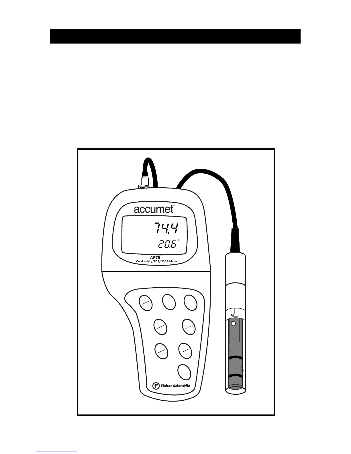
1. Introduction............................................................................................4
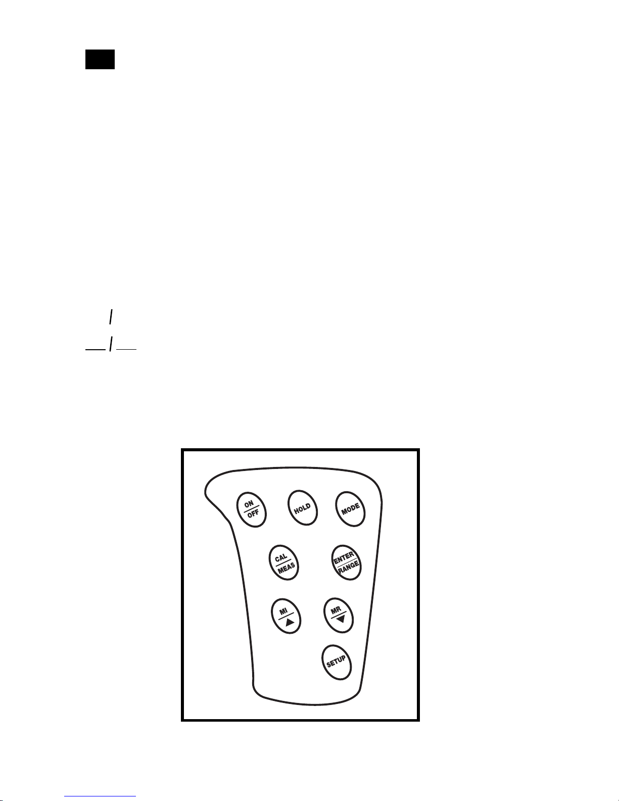
2. Display and keypad functions .............................................................5-6
2.1 Display...................................................................................................................................5
2.2 Keypad...................................................................................................................................6
3. Preparation..........................................................................................7-9
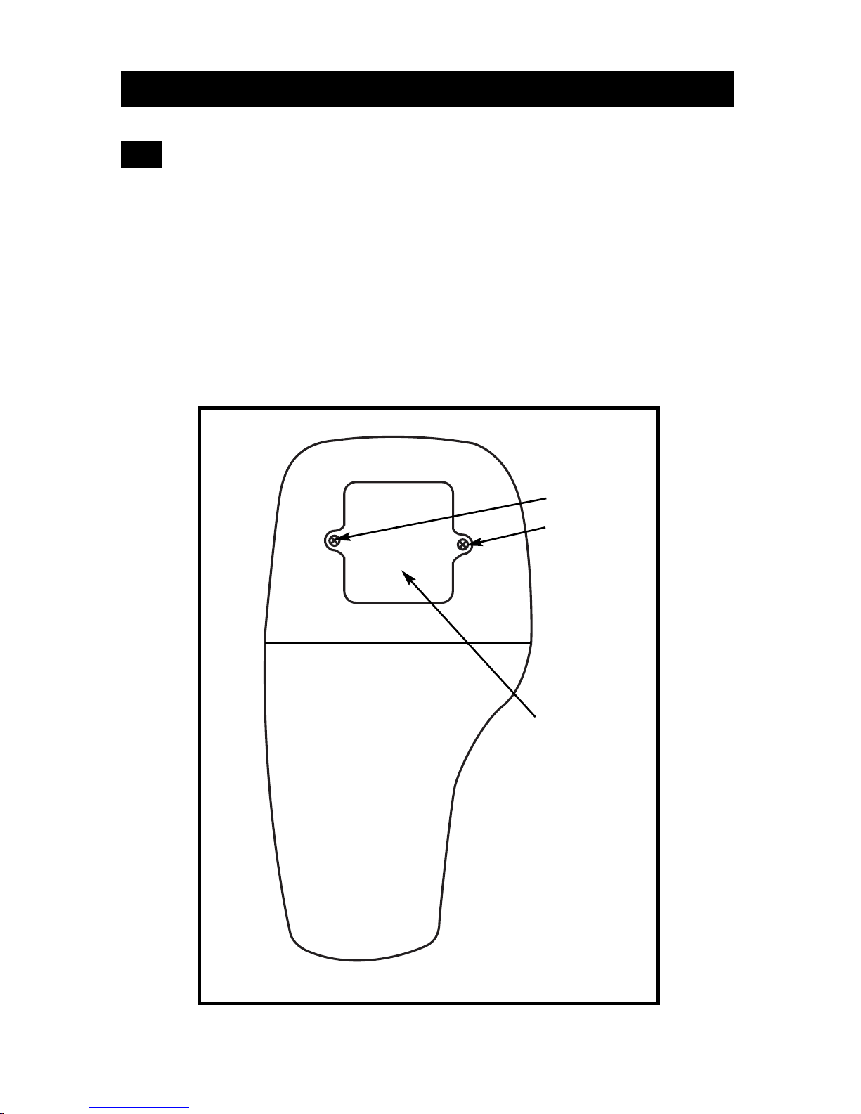
3.1 Inserting the batteries..........................................................................................................7
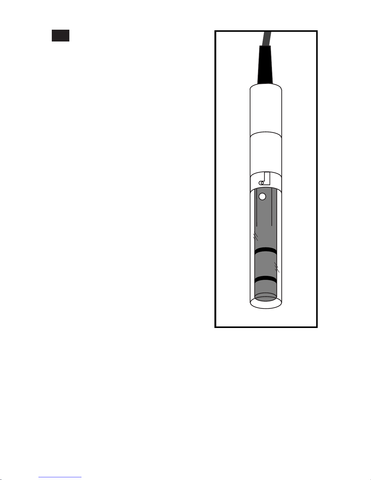
3.2 Probe information ................................................................................................................8
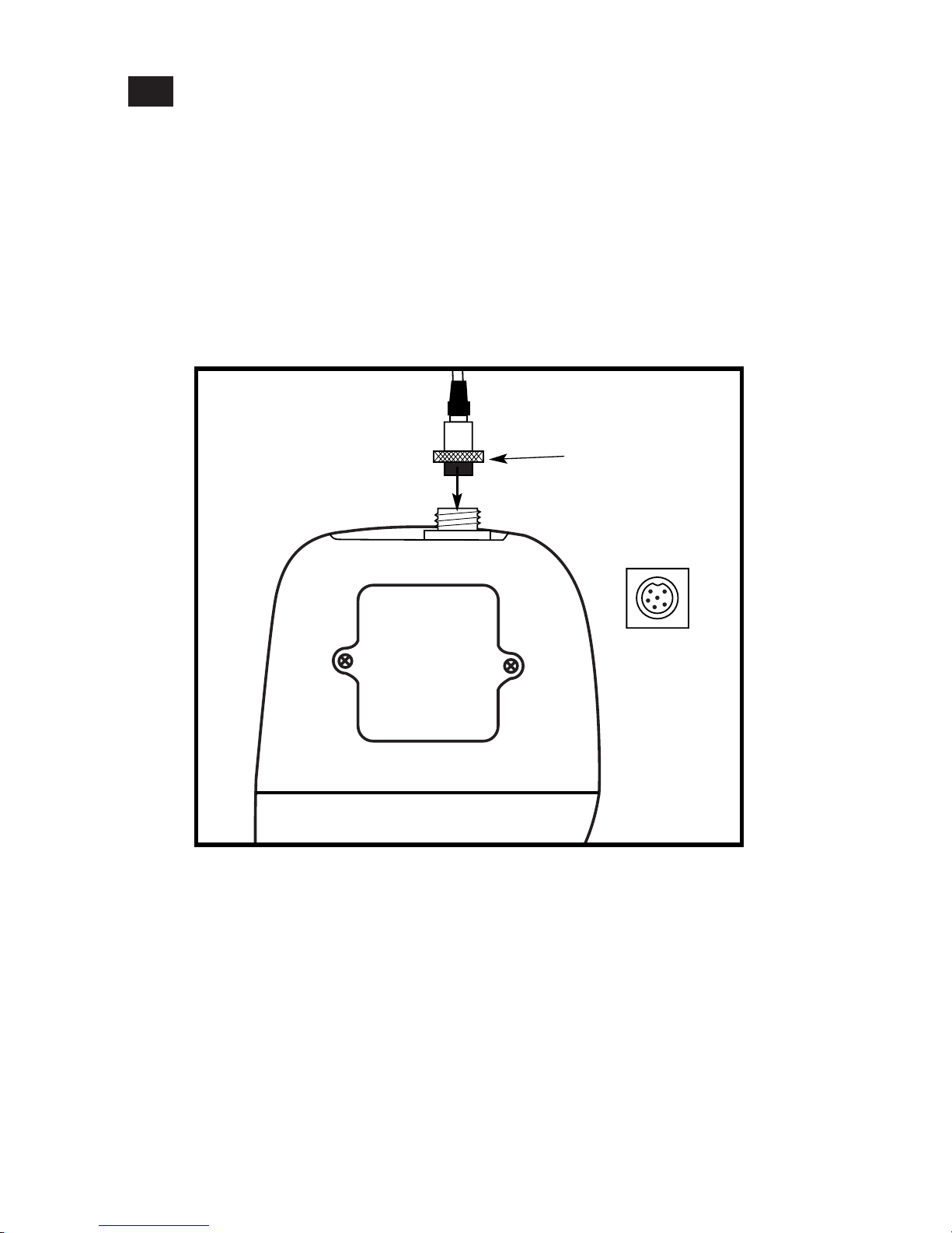
3.3 Connecting the probe to the meter....................................................................................9
4. Calibration.......................................................................................10-16
4.1 Important information on meter calibration .................................................................10
4.2 Preparing the meter for calibration.................................................................................11
4.3 Conductivity calibration..............................................................................................12-13
4.4 TDS calibration..............................................................................................................14-15
4.4.1 Calibrating for TDS directly....................................................................................14
4.4.2 Calibration with conductivity standard and TDS factor....................................15
4.5 Temperature calibration...................................................................................................16
5. Measurement...................................................................................17-22
5.1 Automatic Temperature Compensation (ATC) .............................................................17
5.2 Manual Temperature Compensation.........................................................................18-19
5.3 Taking measurements........................................................................................................20
5.4 Using manual ranging function.......................................................................................21
5.5 Hold function......................................................................................................................22
6. Memory and data input functions..................................................23-24
6.1 Memory input.....................................................................................................................23
6.2 Memory recall.....................................................................................................................24
7. SETUP functions...............................................................................25-40
7.1 Set Up mode overview.................................................................................................26-27
7.2 Program 1.0: Memory clear...............................................................................................28
7.3 Program 2.0: Viewing calibration data............................................................................29
7.4 Program 3.0: Viewing probe data ....................................................................................30
7.5 Program 4.0: Unit configuration.................................................................................31-34
P4.1: READY indicator and auto endpoint function.....................................................31
P4.2: Selecting °C or °F ......................................................................................................32
P4.3 Selecting Automatic or Manual Temperature Compensation.............................33
P4.4 Setting the TDS factor ...............................................................................................34

3
7.6 Program 5.0: Temperature ...........................................................................................35-36
P5.1 Adjusting the temperature coefficient ....................................................................35
P5.2 Adjusting the normalization temperature .............................................................36
7.7 Program 6.0: Selecting the cell constant..........................................................................37
7.8 Program 7.0: Setting the real-time clock....................................................................38-39
7.9 Program 8.0: Resetting to factory defaults.....................................................................40
8. Probe care and maintenance................................................................41
9. Troubleshooting....................................................................................42
10. Error Messages....................................................................................43
11. Specifications......................................................................................44
12. Addendum 1: Calibration tips............................................................45
13. Addendum 2: Conductivity to TDS conversion factors......................46
14: Addendum 3: Calculating TDS Conversion factors ............................47
15. Addendum 4: Calculating temperature coefficients..........................48
16. Addendum 5: Meter factory default settings....................................49

4
1. Introduction
Thank you for selecting an accumet AP75 waterproof portable meter.
• Meter measures conductivity, TDS and temperature.
• Microprocessor-based instrument is completely waterproof—and it floats!
• Meter features a built-in real time clock, expanded memory, and many other user-
friendly features, all of which are accessible through the membrane keypad.
• Meter includes a Ultem/Stainless Steel cell (cell constant K = 1.0) and batteries.
Please read this manual thoroughly before operating your meter.
MODE
HOLD
ENTER
RANGE
ON
OFF
CAL
MEAS
MI
▲
MR
▼
SETUP
ATC
READY
MEAS
C
µS

5
2. Display and Keypad Functions
Display
The LCD has a primary and secondary display.
• The primary display shows the measured conductivity or TDS reading.
• The secondary display shows the temperature of the reading.
The display also shows error messages, keypad functions and program functions.
2.1
Primary display
5.
Secondary display
3.
2.
20.
19.
12.
16.
15. 14.
10.
1.
18.
17.
4.
13.
9.
6.
7. 8.
1. SETup mode indicator
2. MEASurement mode
indicator
3. CALibration indicator
4. MEMory recall mode
indicator
5. millisiemens indicator
6. microsiemens indicator
7. parts per thousand
indicator
8. parts per million
indicator
9. Temperature indicator
10. Automatic
Temperature
Compensation
indicator
11. Clock indicator
12. ERRor indicator
13. MEMory location
indicator
14. Low battery indicator
15. Probe indicator
16. Calibration solution
indicator
16. Function ON/OFF
indicator
17. Cell constant
indicator
18. On/off indicator
19. HOLD indicator
20. READY indicator
11.

6
Keypad
The large membrane keypad makes the instrument easy to use. Each button, when
pressed, has a corresponding graphic indicator on the LCD.
ON/OFF................Powers and shuts off the meter.
HOLD ..................Freezes the measured reading. To activate, press HOLD while in
measurement mode. To release, press HOLD again.
MODE ..................Press to toggle between conductivity, TDS and time
CAL/MEAS..........Toggles user between Calibration and Measurement mode.
NOTE: Temperature calibration is available from conductivity
calibration mode; see page 16 for directions.
ENTER/RANGE..ENTER function: Press to confirm values in Calibration mode
and to confirm selections in Setup mode.
RANGE function: Press to enter manual ranging function.
The MEAS indicator blinks while in manual ranging function.
▲▼
..............Calibration mode: ▲/▼ scrolls through calibration values.
Setup mode: ▲/▼ scrolls through subgroups and program options.
................................MI/MR work in the measurement mode.
MI (memory input) stores the measured value into memory.
MR (memory recall) recalls the sets of values stored in the memory.
SET UP..................Press to enter SETUP mode. SETUP mode lets you customize
meter preferences, view calibration and probe offset data, and
select cell constant.
MI MR
2.2

7
Battery
compartment
Remove these
two screws to
access battery
compartment
3. Preparation
Inserting the Batteries
Four AAA batteries are included with your meter.
1. Use a Phillips screwdriver to remove the two screws holding the battery cover.
See figure below.
2. Lift off battery cover to expose batteries.
3. Insert batteries. Follow the diagram inside the cover for correct polarity.
4. Replace the battery cover into its original position. Screw cover back into place.
3.1

8
Probe information
Your accumet AP75 meter uses a conductivity/
TDS cell with a sturdy 6-pin connector. This cell
is designed for use with accumet waterproof
meters only.
Your meter includes an Ultem/Stainless Steel
cell with a cell constant of K = 1.0. This
conductivity/TDS cell features a built-in tem-
perature sensor for Automatic Temperature
Compensation (ATC). It has a specially
designed housing that provides fast tempera-
ture response and reduces air bubble entrap-
ment, which makes it easy to obtain accurate,
stable readings.
Wetted parts include:
1. Polyetherimide (Ultem)
2. Polybutylterphalate (Valox)
3. Stainless steel (SS 304)
NOTE: We recommend that the you do not sub-
merse the probe above the protective yellow
cap. You can submerse the cable for brief peri-
ods of time, but not continuously.
See section 8 on page 41 for probe care and
maintenance information.
3.2

9
3.3 Connecting the probe to the meter
1. Line up the notch and 6 pins on the meter with the holes in the 6-pin connector.
Push down and turn the locking ring clockwise to lock into place.
See figure below.
2. To remove probe, turn the locking ring counterclockwise on the probe connector.
Pull probe away from the meter.
CAUTION: Do not pull on the probe cord or the probe wires might disconnect.
NOTE: Keep connectors clean. Do not touch connector with soiled hands.
Probe(with 6-pin connector)
locking ring
top view of 6-pin
connector of
temperature probe

10
4.1
4. Calibration
Important Information on Meter Calibration
Your meter has five measuring ranges. You can calibrate at one point in each of the
measuring ranges (up to five points). If you are measuring values in more than one
range, make sure to calibrate each of the ranges you are measuring.
To view current calibration points, see SETUP section Program 2.0 on page 29.
IMPORTANT: You need to calibrate your meter at a standard that is a minimum
of 20% of the range in which you are measuring. For example, use a minimum
calibration value of 400 µS in the 0 to 1999 µS range.
The following table lists the corresponding conductivity and TDS ranges. You
should calibrate each range using a solution that falls between the values in the
“recommended calibration solution range” column.
When you recalibrate your meter, old calibrations are replaced on a range basis.
For example, if you previously calibrated your conductivity meter at 1413 µS in the
0 to 1999 µS range and you recalibrate at 1500 µS (also in the 0 to 1999 µS range),
the meter will replace the old calibration data (1413 µS) in that range. The meter
will retain all calibration data in other ranges.
To completely recalibrate your meter, or when you use a replacement probe, it is best
to clear all calibration data in memory. To erase all old conductivity and TDS calibra-
tion data completely from memory, see SETUP section Program 8.0 on page 40.
Conductivity Recommended Calibration TDS Recommended Calibration
Range Solution Range Range Solution Range
0.00-19.99 µS 6.00 to 17.00 µS 0.00-9.99 ppm 3.00 to 8.50 ppm
0.0-199.9 µS 60.0 to 170.0 µS 10.0-99.9 ppm 30.0 to 85.0 ppm
0-1999 µS 600 to 1700 µS 100-999 ppm 300 to 850 ppm
0.00-19.99 mS 6.00 to 17.00 mS 1.00-9.99 ppt 3.00 to 8.50 ppt
0.0-199.9 mS 60.0 to 170.0 mS 10.0-200 ppt 30.0 to 170 ppt
For information on how to calibrate your meter:
• See section 4.3 on pages 12-13 for Conductivity Calibration.
• See section 4.3 on pages 14-15 for TDS Calibration.
• See section 4.4 on page 16 for Temperature Calibration.
• See Addendum 1 on page 45 for more calibration tips.

11
Preparing the Meter for Calibration
Before starting calibration, make sure you are in the correct measurement mode.
When you switch on the meter, the meter starts up in the units you shut it off in.
For best results, select a standard value close to the sample value you are measuring.
Alternatively use a calibration solution value that is approximately 2⁄3the full scale
value of the measurement range you plan to use. For example, in the 0 to 1999 µS
conductivity range, use a 1413 µS solution for calibration.
Do not reuse calibration solutions after calibration. Contaminants in the solution can
affect the calibration, and eventually the accuracy of the measurements. Use fresh
calibration solution each time you calibrate your meter.
NOTE: These meters are factory set to a temperature coefficient of 2.1% per °C. For
most applications this will provide good results. See Program P5.1 on page
35 to set the temperature coefficient to a different value. See Addendum 3,
“Calculating Temperature Coefficients” on page 48 to determine the
appropriate temperature coefficient for your solution.
NOTE: The factory default value for normalization temperature is 25°C. If you need
to normalize to a value other than 25°C, see Program P5.2 on page 36.
4.2

12
Calibrating for conductivity:
1. If necessary, press the MODE key to
select conductivity mode.
See figure
2. Rinse the probe thoroughly with
de-ionized water or a rinse solution,
then rinse with a small amount of
calibration standard.
3. Dip the probe into the calibration
standard. Immerse the probe tip beyond
the upper steel band. Stir the probe gently
to create a homogeneous sample. Allow
time for the reading to stabilize.
See figure
4. Press CAL/MEAS to enter conductivity
calibration mode. The CAL indicator
will appear in the upper right corner of
the display.
5. Press the MI/▲or MR/▼to change the
value on the primary display to match
the value of the calibration standard.
See figure
6. Press ENTER to confirm the calibration
value. The meter returns to the MEAS
(measurement) mode.
7. Repeat steps 1-6 for other measuring
ranges.
Conductivity calibration
This meter is capable of up to 5-point conductivity calibration at one point per con-
ductivity range (0.00-19.99 µS; 0.0-199.9 µS; 0-1999 µS; 0.00-19.99 mS; 0.0-199.9 mS).
All new calibration data will over-ride existing stored calibration data for each
measuring range you calibrate.
4.3
C
C
A
A
B
B
Immerse
probe beyond
upper steel
band

13
Notes
When entering calibration mode, the meter will display the factory default value. If
the meter was previously calibrated, the display may “jump” to the factory default
value when switching from measurement to calibration mode.
To exit from Conductivity Calibration mode without confirming calibration, DO NOT
press ENTER in step 6. Press CAL/MEAS instead. This will retain the meter’s old calibra-
tion data in the measuring range of the calibration.
You can offset the conductivity reading up to ±20% from the default setting. If your
measured value differs by more than ±20%, clean or replace probe as needed.

14
Notes
To exit from TDS Calibration mode without confirming calibration, DO NOT press
ENTER in step 6. Press CAL/MEAS instead. This will retain the meter’s old calibration
data in the measuring range of the calibration.
You can offset the TDS reading up to ±20% from the default setting. If your meas-
ured value differs by more than ±20%, clean or replace probe as needed.
1. If necessary, press the MODE key to
select TDS mode.
See figure
2. Rinse the probe thoroughly with
de-ionized water or a rinse solution,
then rinse with a small amount of
calibration standard.
3. Dip the probe into the calibration
standard. Immerse the probe tip beyond
the upper steel band. Stir the probe gently
to create a homogeneous sample. Allow
time for the reading to stabilize.
See figure
4. Press CAL/MEAS to enter TDS calibration
mode. The CAL indicator will appear in
the upper right corner of the display.
5. Press the MI/▲or MR/▼to change the
value on the primary display to match
the value of the calibration standard.
See figure
6. Press ENTER to confirm the calibration
value. The meter returns to the MEAS
(measurement) mode.
7. Repeat steps 1-6 for other measuring
ranges.
TDS calibration
4.4.1 Calibrating for TDS directly:
The factory default setting for TDS conversion factor is 0.5. If your solution has a
different TDS factor, you can improve calibration accuracy by setting the TDS factor
prior to calibration. See page 34 for directions.
4.4
C
C
A
A
B
B
Immerse
probe beyond
upper steel
band

15
4.4.2 Calibration with Conductivity standard and TDS factor
The concentration of salts dissolved in solution increases the conductivity of that
solution. This relationship varies from salt to salt and is roughly linear over a given
range for a given salt. The TDS conversion factor is the number used by the meter to
convert from conductivity to TDS.
Instead of calibrating for TDS directly (described in section 4.4.1), you can calibrate
your meter meter by:
1. calibrating to conductivity standards (as described on pages 12-13) and then
2. entering the appropriate TDS conversion factor into the meter.
To determine the conductivity to TDS conversion factor for your solution:
• Addendum 2 on page 46 lists some commonly used conversion factors.
• Addendum 3 on page 47 describes how to calculate the TDS conversion factor for
other solutions.
Enter the TDS conversion factor into your meter as follows:
A
A
B
B
C
C
From measurement mode
1. Press Setup key to enter Set Up mode.
2. Press the ▲and ▼keys to scroll through
subgroups until you view parameter P4.0.
See figure
3. Press the ENTER key five times to select
parameter 4.4. The upper display shows
“tdS” and the lower display shows
“P4.4”.
See figure
4. Press the ENTER key again. The upper
display shows a value and the lower
display shows “tdS”.
See figure
5. Calculate the TDS factor of your
solution. See Addendum 3 on page 47
for information on how to calculate the
TDS factor.
6. Press the ▲and ▼keys to select your
calculated TDS conversion factor.
7. Press the ENTER key to confirm
selection and to return to the subgroup
menu. Press the CAL/MEAS key to
return to measurement mode.

16
Temperature calibration
1. Make sure the cell is attached to the 6-pin
connector. The ATC annunciator will
appear at the right-hand side of the LCD*.
2. Switch the meter on. Press the MODE
key to select conductivity mode.
3. Press the CAL/MEAS key to enter con-
ductivity or TDS calibration mode. The
CAL indicator appears above the primary
display.
See figure
4. While in conductivity or TDS calibration
mode, press the MODE key to enter tem-
perature calibration mode. The primary
display shows the current temperature
reading and the secondary display shows
the factory default temperature value.
See figure
5. Dip the cell into a solution of known
temperature (i.e. a temperature bath).
Allow time for the built-in temperature
sensor to stabilize.
6. Scroll with the ▼and ▲keys to set
the correct temperature value (i.e. the
temperature of the temperature bath).
You can adjust the reading in increments
of 0.1°C.
See figure
7. Once you have selected the correct
temperature, press the ENTER key.
8. Press the CAL/MEAS key to return to
conductivity or TDS measurement mode.
Temperature Calibration
Your probe features a built-in temperature sensor. The temperature sensor is factory
calibrated. Calibrate your sensor only if you suspect temperature errors that may
have occurred over a long period of time or if you have a replacement probe.
4.5
B
B
A
A
Notes
• You can offset the temperature reading up to ±5°C from the original reading.
• To exit this program without confirming the temperature calibration value, DO NOT
press ENTER in step 7. Press CAL/MEAS instead.
*If the ATC indicator does not light, see Program P4.3, on page 33 to switch it on.
C
C

17
5. Measurement
This meter is capable of taking measurements with automatic or manual temperature
compensation. Factory default is ATC on.
Automatic Temperature Compensation
For automatic temperature compensation
(ATC) simply plug the conductivity/TDS
probe into the meter (see page 9 for direc-
tions). The ATC indicator will light on the
LCD.
See figure
Notes
If the ATC indicator does not light, manual
temperature compensation may be selected
in the meter’s Set Up mode. See Program
P4.3 on page 33 for directions on selecting
Automatic Temperature Compensation.
A
A
5.1

18
Manual Temperature Compensation
5.2
From measurement mode
1. Press Setup key to enter Set Up
mode.
2. Press the ▲and ▼keys to scroll
through subgroups until you view
parameter P4.0.
See figure
3. Press the ENTER key three times
to select parameter 4.3. The upper
display shows “ATC” and the lower
display shows “P4.3”.
See figure
4. Press the ENTER key again. The
upper display shows “ATC” and the
lower display shows “YES” or “NO”.
See figure
5. Press the ▲and ▼keys to select
the Automatic Temperature
Compensation feature on of off.
• YES = ATC on
• NO = ATC off
6. Press the ENTER key to confirm
selection and to return to the sub-
group menu. Press the CAL/MEAS
key to return to measurement mode.
IMPORTANT: For manual compensation, you must deactivate the temperature
probe.
5.2.1 Selecting Manual Temperature Compensation
Select between Automatic Temperature Compensation (ATC) and Manual
Temperature Compensation in the Set Up Program P4.3. Meter default is ATC on.
A
A
B
B
C
C

19
5.2.2 Setting a manual temperature compensation value
To use manual temperature compensation, you need to enter the temperature value
of your process into the meter. This is the value at which readings will manually
temperature compensate. You can select any temperature between 0 and 100°C
(32 and 212°F). Default value is 25°C.
D
D
E
E
To select a manual temperature
compensation value:
1. Switch the meter on. Press the MODE
key to select measurement mode.
2. If necessary, select ATC off as described
in section 5.2.1 on page 18. The ATC
indicator will not appear on the display.
3. Press the CAL/MEAS key to enter
conductivity or TDS calibration mode.
The CAL indicator will appear above the
primary display.
See figure
4. While in conductivity or TDS calibration
mode, press the MODE key to enter tem-
perature calibration mode. The primary
display shows the current temperature
setting and the secondary display shows
the default value 25°C (77°F).
See figure
5. Check the temperature of your sample
using an accurate thermometer.
6. Press the ▲or ▼keys to offset the
temperature to the measured value
from step 5.
See figure
7. Press ENTER to confirm the selected
temperature and to return to the con-
ductivity or TDS measurement mode.
The meter will now compensate
conductivity or TDS readings for the
manually set temperature.
F
F
Notes
To exit this program without confirming the manual temperature compensation value,
DO NOT press ENTER in step 7. Press CAL/MEAS instead.
Table of contents
Other Accumet Measuring Instrument manuals
Popular Measuring Instrument manuals by other brands

ero electronic
ero electronic DPS instruction manual

Keysight Technologies
Keysight Technologies MXA Series Installation note

Oakton
Oakton pH 610 instruction manual

Keysight
Keysight PXA N9030A Installation note

HEIDENHAIN
HEIDENHAIN MSE 1202 installation instructions

SICK
SICK InspectorP Rack Fine Positioning operating instructions