Accumet AP71 User manual

OPERATING INSTRUCTIONS
accumet®13636AP71 and 13636AP72
AP71 and AP72
Portable Waterproof
pH/mV/°C Meter
1/02
IP
67

32
Table of Contents
1. Introduction..............................................................................................4
2. Display and keypad functions...............................................................5-6
2.1 Display......................................................................................................................................5
2.2 Keypad .....................................................................................................................................6
3. Preparation..........................................................................................7-11
3.1 Inserting the batteries.............................................................................................................7
3.2 Connecting the electrode and temperature probe..........................................................8-9
3.3 Attaching the electrode holder to the meter.....................................................................10
3.4 Inserting the electrode into the electrode holder.............................................................11
4. Calibration.........................................................................................12-17
4.1 Important information on meter calibration....................................................................12
4.2 Preparing the meter for calibration ...................................................................................13
4.3 pH calibration..................................................................................................................14-15
4.4 Relative mV calibration.......................................................................................................16
4.5 Temperature calibration ......................................................................................................17
5. Measurement.....................................................................................18-21
5.1 Automatic Temperature Compensation............................................................................18
5.2 Manual Temperature Compensation.................................................................................19
5.3 Taking Measurements ....................................................................................................20-21
6. Hold function..........................................................................................22
7. Memory functions .............................................................................23-24
7.1 Memory Input .......................................................................................................................23
7.2 Memory Recall ......................................................................................................................24
8. Advanced setup functions.................................................................25-39
8.1 Advanced setup mode overview..................................................................................26-27
AP71 meter ...........................................................................................................................26
AP72 meter ...........................................................................................................................27
8.2 Program 1.0: Memory clear.................................................................................................28
8.3 Program 2.0: Viewing previous calibration data .............................................................29
8.4 Program 3.0: Viewing electrode data ...........................................................................30-31
P3.1 Electrode offset ............................................................................................................30
P3.2 Electrode slope.............................................................................................................31
8.5 Program 4.0: Unit configuration ...................................................................................32-33
P4.1: READY indicator and auto endpoint function......................................................32
P4.2: Selecting number of pH calibration points ............................................................33
P4.3: Calibration buffer selection sets (AP72 meter only) ...............................................34
P4.4 Selecting °C or °F (AP72 meter only).........................................................................35
8.6 Program 5.0: Resetting to factory default settings (AP71 meter only)...........................36
8.7 Program 5.0: Setting the real-time clock (AP72 meter only).......................................37-38
8.8 Program 6.0: Resetting to factory default settings (AP72 meter only)...........................39
9. Probe care and maintenance ............................................................40-41
10. Troubleshooting ...................................................................................42
11. Error Messages......................................................................................43
12. Specifications........................................................................................44

54
1. Introduction
Thank you for selecting an accumet meter. This accumet portable meter
is a microprocessor-based instrument that measures pH, mV, and temperature.
It’s completely waterproof—and it floats! Your meter has many user-friendly
features, all of which are accessible through the membrane keypad.
This meter includes two electrode holders and batteries.
Please read this manual thoroughly before operating your meter.
2. Display and Keypad Functions
Display
The LCD has a primary and secondary display.
• The primary display shows the measured pH, mV or Relative mV reading.
• The secondary display shows the temperature.
The display also shows error messages, keypad functions and program functions.
2.1
Primary display
5.
6.
Secondary display
3.
2.
18.
17.
11.
15.
14. 13.
9.
1.
16.
4.
12.
8.
7.
1. SETup mode indicator
2. MEASurement mode
indicator
3. CALibration indicator
4. MEMory recall mode
indicator
5. mV or relative mV
indicator
6. pH indicator
7. Temperature indicator
(°F available on
AP72 meter only)
8. pH buffer selection
indicator
9. Automatic Temperature
Compensation
indicator
10. Clock indicator
(AP72 meter only)
11. ERRor indicator
12. MEMory location
indicator
13. Low battery indicator
14. Probe indicator
15. Buffer indicator
16. Function ON/OFF
indicator
17. HOLD indicator
18. READY indicator
10.

76
Keypad
The large membrane keypad makes the instrument easy to use. Each button,
when pressed, has a corresponding graphic indicator on the LCD.
ON/OFF............Powers and shuts off the meter.
HOLD ..............Freezes the measured reading. To activate, press HOLD while in
measurement mode. To release, press HOLD again.
AP72 model only: When auto endpoint feature is switched on,
it automatically holds reading after 5 seconds of stability. The
HOLD indicator appears on the display. Press HOLD to release
auto endpoint feature.
MODE ..............Selects the measurement parameter. Press MODE to toggle between
pH; mV (or relative mV); and date/time (date/time available on
AP72 model only). In pH calibration mode, press MODE to access
temperature calibration.
CAL/MEAS......Toggles user between Calibration and Measurement mode.
• If you were in pH measurement mode, press CAL/MEAS
to enter pH calibration mode.
• If you were in mV measurement mode, press CAL/MEAS
to enter mV calibration mode.
NOTE: Temperature calibration is available from pH calibration mode;
see page 17 for directions.
In advanced set-up mode: Press CAL/MEAS to return to main menu
from sub menus. Press CAL/MEAS again to return to measurement
mode from main menu.
ENTER ............Press to confirm values in Calibration mode and to confirm
selections in Setup mode.
▲▼
..........Press ▲/▼in setup mode to scroll through subgroups. Also press
▲/▼ in mV calibration mode to adjust the calibration value.
MI/MR work in the measurement mode. MI (memory input) stores
the measured value into memory. MR (memory recall) recalls the sets
of values stored in
the memory.
SET....................Press to enter SETUP
mode. SETUP mode
lets you customize meter
preferences and defaults,
and view calibration and
electrode offset data.
MI MR
2.2
Battery
compartment
Remove these
two screws to
access battery
compartment
3. Preparation
Inserting the Batteries
Four AAA batteries are included with your meter.
1. Use a Phillips screwdriver to remove the two screws holding the battery cover.
See figure below.
2. Lift off battery cover to expose batteries.
3. Insert batteries. Follow the diagram inside the cover for correct polarity.
4. Replace the battery cover into its original position. Screw cover back into place.
3.1

98
Connecting the Electrode and Temperature Probe
This accumet pH/mV meter can use any standard pH, ORP, or ISE electrode with
a BNC connector. For automatic temperature compensation (ATC), this meter
requires a temperature probe with a specialty 6-pin connector.
Use either:
• any electrode with a BNC connector and a separate temperature probe with
6-pin connector
• an “All-in-One” combination pH electrode/temperature probe designed
specifically for the AP71 and AP72 waterproof meters
NOTE: Keep connectors clean. Do not touch connector with soiled hands.
3.2
To connect the pH, ORP or ISE electrode:
1. Slide the BNC connector of the probe over the BNC connector socket on the
meter. Make sure the slots of the connector are in line with the posts of the
socket. Rotate and push the connector clockwise until it locks.
See figure below.
2. To remove probe, push and rotate the connector counterclockwise. While
holding onto the metal part of the connector, pull probe away from the meter.
CAUTION: Do not pull on the probe cord or the probe wires might disconnect.
To connect the temperature probe:
1. Line up the notch and 6 pins on the meter with the holes in the 6-pin connector.
Push down and turn the locking ring clockwise to lock into place.
See figure below.
2. To remove probe, turn the locking ring counterclockwise on the probe connector.
Pull probe away from the meter.
CAUTION: Do not pull on the probe cord or the probe wires might disconnect.
Temperature probe
(with 6-pin connector)
locking ring
Electrode
(with BNC connector)
top view of 6-pin
connector of
temperature probe

1110
3.3 Attaching the Electrode Holder
to the Meter
Attaching the electrode holder to the meter
facilitates one-hand operation. Attach two
electrode holders if you have a separate electrode
and temperature probe.
1. Locate the slot on the left hand side of
the meter.
2. Gently slide the flange of the holder into the
slot on the meter. Make sure the holder is
secured properly into the slot.
See figure
You can attach the electrode holder in different
positions.
See figure
To attach a second electrode holder:
3. Align the flange of the second electrode holder
with the slot of the first holder.
See figure
4. Slide the flange of the second holder into the
slot of the first holder until the tops of the hold-
ers are aligned and secure.
Inserting the Electrode into the Electrode Holder
Do not use excessive force when inserting electrodes into the holders.
1. Insert the pH electrode into the opening of the first holder until the top housing
of the electrode touches the top of the holder.
2. If you are using a separate temperature probe, insert the probe into the opening
of the second holder until the ridge on the housing touches the top of the holder.
NOTE: The holder is designed for probes 12 mm in diameter. Electrodes larger than
12 mm may not fit in the holder. Forcing the electrode into the opening may
damage the holder or your electrode.
B
A
B
A3.4
C
C

1312
AP71 meter calibration
The AP71 meter is capable of up to 5-point pH calibration to ensure accuracy across the
entire pH range of the meter. Select from the following buffer options:
pH 1.68, 4.01, 7.00, 10.00, and 12.45.
The meter automatically recognizes and calibrates to these standard buffer values,
which makes pH calibration faster and easier.
AP72 meter calibration
The AP72 meter features three separate buffer sets. Select the buffer set you require
in Set Up mode Program 4.0 (see page 34 for more information). The AP72 meter is
capable of up to 6-point pH calibration, depending on the buffer set. Select from the
following buffer options:
USA buffers (pH 1.68, 4.01, 7.00, 10.00, 12.45)
NIST buffers (pH 1.68, 4.01, 6.86, 9.18, 12.45)
DIN buffers (pH 1.09, 3.06, 4.65, 6.79, 9.23, 12.75)
The meter automatically recognizes and calibrates to these standard buffer values,
which makes pH calibration faster and easier.
For information on how to calibrate your meter:
• See section 4.3 on pages 14-15 for pH calibration
• See section 4.4 on page 16 for Relative mV calibration
• See section 4.5 on pages 17 for Temperature Calibration of replacement
temperature probes or replacement “All-in-One” electrodes
Preparing the Meter for Calibration
Before starting calibration, make sure you are in the correct measurement mode.
When you switch on the meter, the meter starts up in the units last used. For
example, if you shut the meter off in "mV" units, the meter will read "mV" units
when you switch the meter on.
Be sure to remove the protective electrode storage bottle or rubber cap of the
probe before calibration or measurement. If the electrode has been stored dry,
wet the probe in tap water for 10 minutes before calibrating or taking readings to
saturate the pH electrode surface and minimize drift.
Wash your probe in deionized water after use, and store in electrode storage solu-
tion. If storage solution is not available, use pH 4.0 or 7.0 buffer.
Do not reuse buffer solutions after calibration. Contaminants in the solution can
affect the calibration, and eventually the accuracy of the measurements.
4. Calibration
Important Information on Meter Calibration
When you recalibrate your meter, old pH, Rel mV and mV calibration points are replaced on
a point by point basis. For example, if you previously calibrated your meter at pH 4.01, 7.00,
and 10.01, and you recalibrate at pH 7.00, the meter retains the old calibration data at
pH 4.01 and pH 10.01. To view current calibration points, see Program P2.0 in the SETUP
section, page 29.
To completely recalibrate your meter, or when you use a replacement probe, it is best to set the
meter to its factory defaults and recalibrate the meter at all points. To reset the meter to its
factory defaults, see the SETUP section Program P5.0, page 36 (for AP71 meter) or Program
P6.0, page 39 (for AP72 meter).
4.2
4.1

1. If necessary, press the MODE key to
select pH mode. The pH indicator
appears in the upper right hand corner
of the display.
See figure
2. Rinse the probe thoroughly with
de-ionized water or a rinse solution. Do
not wipe the probe; this causes a build-up
of electrostatic charge on the glass surface.
3. Dip the probe into the calibration buffer.
The end of the probe must be completely
immersed into the sample. Stir the probe
gently to create a homogeneous sample.
4. Press CAL/MEAS to enter pH calibration
mode. The CAL indicator lights. The
primary display will show the measured
reading while the smaller secondary dis-
play will indicate the pH standard buffer
solution.
See figure
5. Wait for the measured pH value to
stabilize.
See figure
1514
6. Press ENTER to confirm calibration.
The meter is now calibrated to the
current buffer.
See figure
• If you are performing multipoint
calibration, go to step 7.
• If you are performing one-point
calibration, go to step 9.
7. Rinse the probe with de-ionized water
or a rinse solution, and place it in the
next pH buffer.
8. Follow steps 5 to 8 for additional
calibration points.
9. When calibration is complete,
press CAL/MEAS to return to pH
measurement mode.
Notes
To exit from pH Calibration mode without
confirming calibration, DO NOT press
ENTER in step 6. Press CAL/MEAS instead.
If the selected buffer value is not within
±1.0 pH from the measured pH value: the
electrode and buffer icon blink and the ERR
annunciator appears in the lower left corner
of the display.
To limit the number of pH buffer values
available during calibration, see section P4.2
on page 33.
D
C
D
B
C
B
A
A
pH calibration
NOTE: We recommend that you perform at least a 2-point calibration using standard
buffers that bracket (one above and one below) the expected sample range.
You can perform a 1-point calibration, but make sure that the buffer value is
close to the sample value you are measuring.
4.3
C
If the READY indicator has been activiated
(set up program P4.1—see page 32), the READY
annunciator lights when the reading is stable.

Temperature calibration
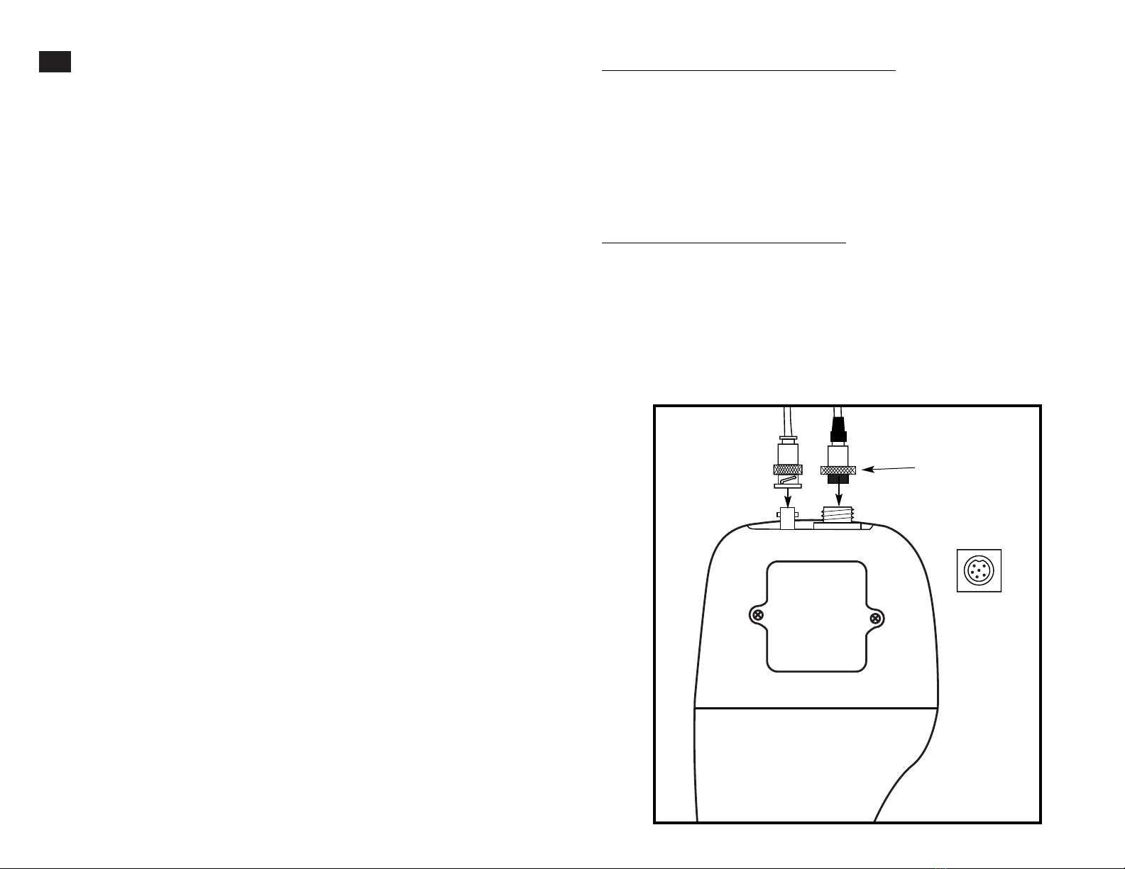
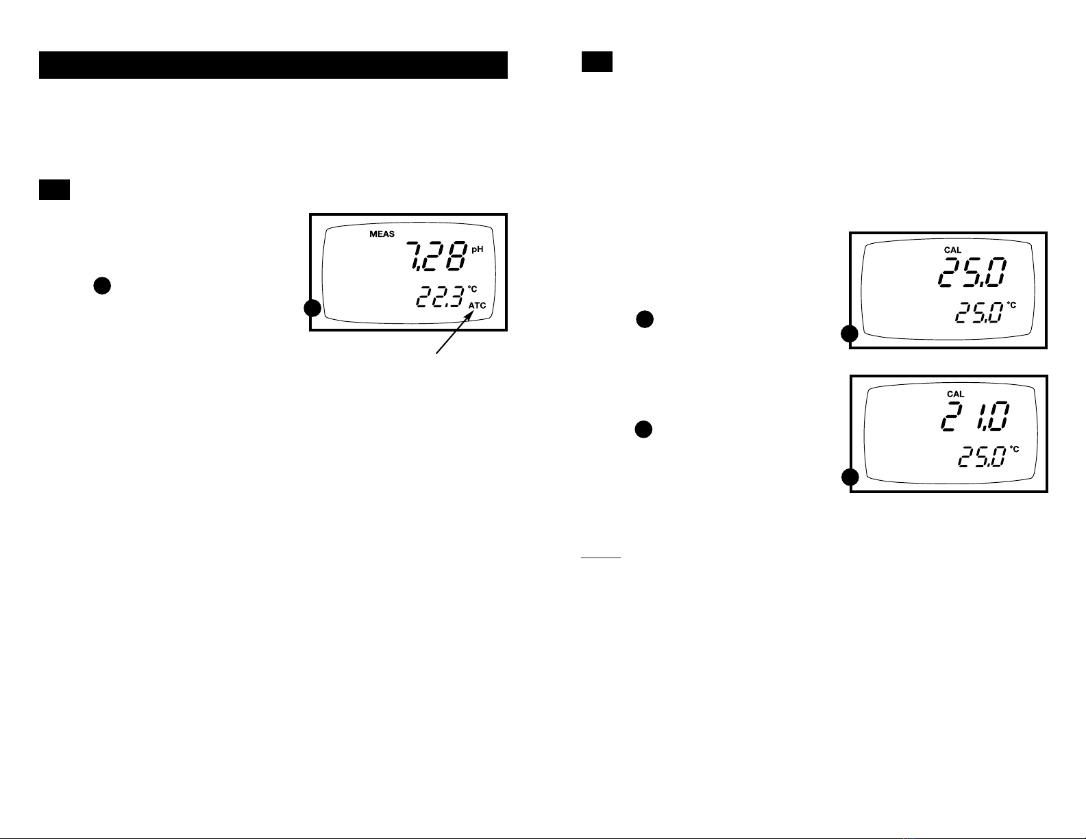
1. Make sure the ATC probe (or
temperature connector of the “All-in-
One” electrode) is attached to the 6-pin
connector. The ATC annunciator will
appear at the right-hand side of the LCD.
2. Switch the meter on. Press the MODE
key to select pH mode.
3. Press the CAL/MEAS key to enter pH
calibration mode. The CAL indicator will
appear above the primary display.
4. While in pH calibration mode, press the
MODE key to enter temperature calibra-
tion mode. The primary display shows the
temperature value with the last set offset
and the secondary display shows the
factory default temperature value.
See figure
5. Dip the ATC probe (or “All-in-One”
electrode) into a solution of known
temperature (i.e. a temperature bath).
Allow time for the temperature probe to
stabilize.
6. Scroll with the ▼and ▲keys to set
the correct temperature value (i.e. the
temperature of the temperature bath).
You can adjust the reading in increments
of 0.1°C.
See figure
7. Once you have selected the correct
temperature, press the ENTER key.
The meter automatically returns to
pH measurement mode.
1716
Temperature Calibration
The temperature sensor is factory calibrated. Calibrate your sensor only if you
suspect temperature errors that may have occurred over a long period of time
or if you have a replacement probe.
4.5
B
B
A
A
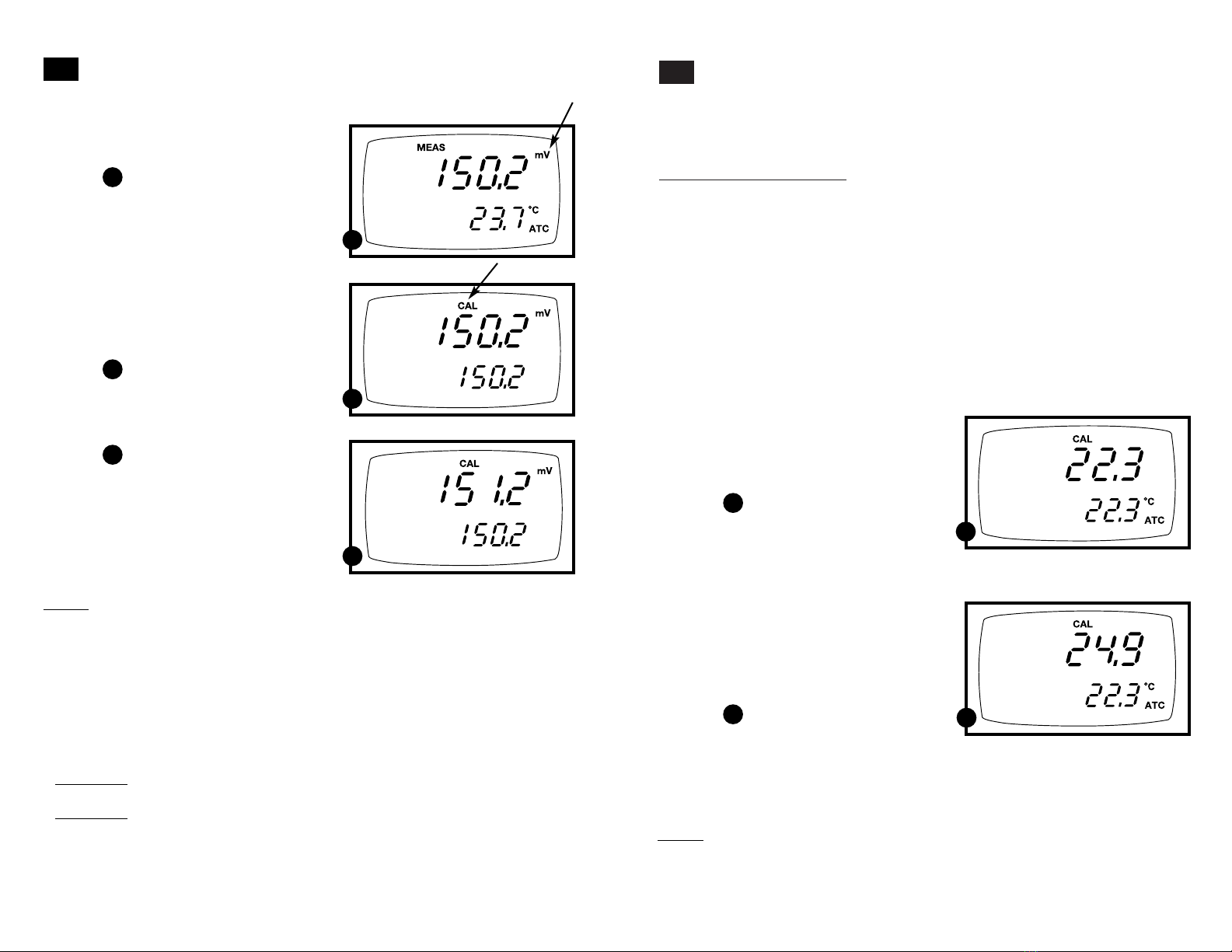
Relative mV Calibration
1. While in the measurement function,
press MODE to enter the mV mode.
The mV indicator appears in the upper
right hand corner.
See figure
2. Press the CAL/MEAS key. The CAL
indicator appears above the primary
display. The primary display shows the
relative mV reading and the secondary
display shows the absolute mV value.
NOTE: If you have never calibrated
relative mV or if the meter has been reset,
the value shown in the primary display is
the same as the absolute mV value.
See figure
3. Press the ▲or ▼keys to enter the
relative mV value that matches your
desired reading.
See figure
4. Press the ENTER key to confirm
the reading and to return to the
measurement mode. The primary
display now shows the relative mV
reading. The RmV indicator appears
in the upper right hand corner.
Notes
To view the mV offset value, use the
SETUP mode Program P3.1. See page
30 for instructions.
The relative mV (RmV) indicator appears
whenever the mV offset is not zero.
To reset the all calibration and offset values
in memory to the factory default settings,
use:
• AP71 meter:SETUP Program P 5.0.
See page 36.
• AP72 meter: SETUP Program P6.0.
See page 39.
4.4
C
C
B
B
A
A
Notes
• You can offset the temperature reading up to ±5°C from the original reading.
• To exit this program without confirming the temperature calibration value, DO NOT
press ENTER in step 7. Press CAL/MEAS instead.

1918
IMPORTANT: For manual compensation,
you must disconnect the temperature probe
(see page 9).
1. Switch the meter on. Press the MODE
key to select pH mode.
2. Press the CAL/MEAS key to enter pH
calibration mode. The CAL indicator
will appear above the primary display.
3. While in pH calibration mode, press
the MODE key to enter temperature
calibration mode. The primary display
and secondary display show the last
set value.
See figure
4. Check the temperature of your sample
using an accurate thermometer.
5. Press the ▲or ▼keys to offset the
temperature to the measured value
from step 4.
See figure
6. Press ENTER to confirm the selected
temperature and to return to the pH
measurement mode.
The meter will now compensate pH
readings for the manually set temperature.
Notes
To exit this program without confirming the
manual temperature compensation value,
DO NOT press ENTER in step 6. Press
CAL/MEAS instead.
Manual Temperature Compensation
A
A
5.2
5. Measurement
This meter is capable of taking measurements with automatic or manual temperature
compensation. Automatic temperature compensation only occurs when a temperature sensor
is plugged into the meter. If there is no temperature sensor plugged into the meter, the default
manual temperature setting is automatically 25°C. You can manually set the temperature to
match your working conditions using a separate thermometer.
Automatic Temperature Compensation
For automatic temperature compensation
(ATC) simply plug the temperature probe
into the meter (see page 9 for directions).
The ATC indicator will light on the LCD.
See figure
NOTE: If you are using a temperature
probe, the probe must be submersed in the
liquid you are measuring.
A
A
5.1
B
B

To take readings:
1. Rinse the probe with deionized or
distilled water before use to remove any
impurities adhering to the probe body.
If the pH electrode has dehydrated, soak
it for 30 minutes in electrode storage
solution or a 2M–4M KCl solution.
2. Press ON to switch on meter. The
MEAS annunciator appears on the top
center of the LCD. The ATC indicator
appears in the lower right hand corner
to indicate Automatic Temperature
Compensation (See page 19 to set
Manual Temperature Compensation).
See figure
3. Dip the probe into the sample.
When dipping the probe into the sample,
the sensor or the glass bulb of the electrode
must be completely immersed into the sam-
ple. Stir the probe gently in the sample to
create a homogenous sample.
4. Allow time for the reading to stabilize.
Note the reading on the display.
5. To toggle between pH and mV (or Rel
mV) readings, press the MODE key.
2120
Taking Measurements
Be sure to remove the electrode soaker bottle or protective rubber cap on the
electrode before measurement.
A
A
5.3
Taking measurements with READY indicator selected on
If the READY indicator has been activated, the READY annunciator lights when
the reading is stable*. Switch the READY indicator on or off in Set up program
P4.1—see page 32 for directions.
*The READY indicator appears and the reading holds until the measured value exceeds the tolerance
(± 0.02 pH; ± 0.8 mV <400; ±1.2 mV >400). Then, the READY annunciator turns off.
Taking measurements with the auto endpoint feature selected on
NOTE: this feature is available on model AP72 only.
When a reading is stable for more than 5 seconds, the auto endpoint feature will
automatically “hold” the reading. The “hold” indicator appears on the left side of the
display. Press the HOLD key to release the reading. Switch the Auto endpoint feature
on or off in Set up program P4.1—see page 32 for directions.

This feature lets you freeze the value
of the pH, mV (or Relative mV) and
temperature readings for a delayed
observation. HOLD can be used any
time when in MEAS mode.
1. To hold a measurement, press the
HOLD key while in measurement
mode. "HOLD" will appear on the
display.
See figure
2. To release the held value, press HOLD
again. Continue to take measurements.
NOTE: This meter shuts off automatically
after 30 minutes of nonuse.
If the meter is shut off either
automatically or manually, the
HOLD value will be lost. For
longer storage, use the memory
functions (see pages 23-24).
NOTE: For AP72 model only: The AP72meter
has an auto endpoint feature. When
this feature is switched on, the
display will automatically “hold”
a reading that has been stable for
more than 5 seconds. The “hold”
indicator appears. Press the HOLD
key to release the reading.
To switch on or off the auto endpoint
feature, see Set up program P4.1
on page 32.
2322
7. Memory functions
Memory Input
Your meter stores data in sets:
• pH and temperature
• mV (or relative mV) and temperature.
AP71 meter: The AP71 meter can store up to 16 sets of data in any combination of
values. For example, you can store 7 pH and 9 mV values.
AP72 meter: The AP72 meter can store up to 50 sets of data in any combination of
values. In addition to the standard data set, the AP72 meter also stores the date and
time the reading was stored.
7.1
A
To store a reading:
1. During any measurement function
(MEAS), press the MI key to input any
data into the memory
2. MEM, “Sto” and memory number
will flash. The meter then returns to
measurement mode.
See figure
NOTE: If the memory is full, the first value
stored will be erased to create space
for the new value.
A
A
6. HOLD function
A

2524
8. Advanced set up functions
The advanced set up mode lets you customize your meter’s preferences and
defaults. Your waterproof meter features different sub groups that organize
all set-up parameters.
The sub groups are:
1. P1.0: Memory clear (CLR)
2. P2.0: Viewing calibration data (CAL)
3. P3.0: Viewing electrode data (ELE)
4. P4.0: Unit configuration (COF)
5. AP71 only: P5.0: Reset to factory default settings (rSt)
AP72 only: P5.0: Setting clock (CLO)
6. AP72 only: P6.0: Reset to factory default settings (rSt)
To recall readings:
1. Press the MR key once to retrieve the
last reading stored. The memory location
screen—MEM, “Loc” and the memory
number—will flash on the display.
See figure
2. Press the ENTER key to recall the read-
ing stored under that memory number.
See figure
3. AP71 meter only: Press the ENTER key
again to return to the “memory location”
screen.
AP72 meter only: Press the ENTER
key again to view the date and time
the reading was taken. Press the
ENTER key again to return to the
“memory location” screen.
See figure
4. The display automatically moves to
the next memory location screen.
See figure
5. If necessary, press the ▲key to select
the next “memory location” screen;
press the ▼ key to select the previous
“memory location” screen.
6. Repeat steps 2-5 to review additional
stored data sets.
7. To exit Memory Recall, press the MEAS
key to return to the Measurement mode.
Memory Recall
This function recalls the previous readings stored in the memory. You can only
access MR from the MEASurement mode. Memory recall is in “Last In First Out”
order.
7.2
B
C
C
D
E
E
D
Notes
Readings stored in memory are retained even if the unit is turned off. To erase all
readings stored in memory, use the SETUP mode P1.0 on page 28.
Time/date appears on AP72 meter display only
AP71 meter advanced
set up subgroups
AP72 meter advanced
set up subgroups
B

AP71 meter set up mode
2726
Advanced set-up mode overview
P3.0: Viewing electrode data
In pH measurement mode:
• P3.1: pH electrode offset
• P3.2: pH electrode slope
In mV (or relative mV) measurement mode:
• P3.1: relative mV offset
P1.0: Memory clear
• P1.0 Clear all stored readings
P2.0: Viewing previous calibration data
• P2.1: First calibration point
• P2.2: Second calibration point
• P2.3: Third calibration point
• P2.4: Fourth calibration point
• P2.5: Fifth calibration point
Instructions on page 28
Instructions on page 36
Instructions on page 29
8.1
Instructions on page 30-31
P4.0: Unit configuration
• P4.1: Ready indicator on or off
• P4.2: # of calibration points: 2, 3, 4, or 5
P5.0: Reset to factory default
• P5.0: Reset to factory default settings
Instructions on pages 32-33
Press the SETUP key to enter Set up mode.
Press the ▲and ▼keys to scroll through sub groups.
AP72 meter set up mode
P3.0: Viewing electrode data
In pH measurement mode:
• P3.1: pH electrode offset
• P3.2: pH electrode slope
In mV (or relative mV) measurement mode:
• P3.1: relative mV offset
P1.0: Memory clear
• P1.0 Clear all stored readings
P2.0: Viewing previous calibration data
• P2.1: First calibration point (plus time/date)
• P2.2: Second calibration point (plus time/date)
• P2.3: Third calibration point (plus time/date)
• P2.4: Fourth calibration point (plus time/date)
• P2.5: Fifth calibration point (plus time/date)
• P2.6: Sixth calibration point (plus time/date)-only
available when DIN buffer set is selected in P4.3
Instructions on page 28
Instructions on page 39
Instructions on page 29
Instructions on page 30-31
P4.0: Unit configuration
• P4.1: Ready indicator on or off
• P4.2: # of calibration points: 2, 3, 4, 5, or 6
(6th point available for DIN buffer set only)
• P4.3: Select calibration buffer set: USA, DIN, or NIST
• P4.4: Select °C or °F
P6.0: Reset to factory default
• P6.0: Reset to factory default settings
Instructions on pages 32-35
Instructions on pages 37-38
P5.0: Setting Clock
• Setting year
• Setting date (month/day)
• Setting time (hour/minute/second)

From measurement mode:
1. Press the Set up key to enter
Set Up mode.
See figure
2. Press the ▲and ▼keys to scroll through
subgroups until you view parameter P2.0.
3. AP71 meter only: Press the ENTER key
repeatedly to view previous calibration
data.
See figure
AP72 meter only: Press the ENTER key
repeatedly to view previous calibration
data. The meter will first display the
calibration point, and then display the
date and time of calibration.
See figures and
4. When you have scrolled through all
calibration data, you will automatically
return to the subgroup menu. Press
the CAL/MEAS key to return to
measurement mode.
Notes
If there is no previous calibration data at a
particular point, the primary display will
show “----”.
2928
P1.0: Memory Clear
Use this parameter to clear all memory values when you need to store a new series of
values. This lets you avoid confusing the old values with the new ones. NO is the
default setting.
NOTE: Selecting YES will wipe out all memory.
8.2
A
A
B
B
From measurement mode:
1. Press the Set up key to enter Set Up
mode.
2. Press the ▲and ▼keys to scroll through
subgroups until you view parameter P1.0.
See figure
3. Press the ENTER key to enter parameter
P1.0.
4. Press the ▲and ▼keys to toggle
between NO and YES.
• NO retains current memory
• YES clears all memory
See figure
5. Press the ENTER key to confirm selection
and return to the subgroup menu.
Press the CAL/MEAS key to return
to measurement mode.
P2.0: Viewing previous calibration data
This mode lets you recall previous calibration data, which helps you know when to
recalibrate your meter. This is a “view only” mode.
8.3
A
A
B
C
B
C
B
Time/date appears on AP72 meter display only

P3.1: Electrode offset
From measurement mode
1. Press the Setup key to enter Set Up
mode.
2. Press the ▲and ▼keys to scroll through
subgroups until you view parameter
P3.0.
See figure
3. Press the ENTER key to select
parameter 3.1.
4. The display shows the electrode offset
value.
• If you are in pH measurement mode,
the display shows the mV offset at
pH 7.00. If you have not calibrated at
any buffer, the primary display shows
0.0 mV.
See figure
• If you are in mV measurement mode,
the display shows the relative mV
offset. You can adjust the relative mV
offset in relative mV calibration
mode—see page 16 for instructions.
See figure
5. Press the ENTER key to to proceed to
step 4 of P3.2. Or, press the CAL/MEAS
key to return to measurement mode.
3130
P3.0: Viewing electrode data
Program 3 has two “view only”options that lets you check the electrode parameters
for diagnostic purposes.
A
A
B
B
D
D
E
E
8.4
P3.2: Electrode slope
NOTE: this parameter is available in
pH measurement mode only.
From measurement mode
1. If necessary, press the MODE key to
select pH measurement mode. Press
the Setup key to enter Set Up mode.
2. Press the ▲and ▼keys to scroll through
subgroups until you view parameter
P3.0.
See figure
3. Press the ENTER key twice to select
parameter 3.2.
4. The display shows electrode slope
in percentage. Slope displayed is
the average slope based on the pH
calibrations. Default setting is 100.0.
See figure
5. Press the ENTER key to return to the
subgroup menu. Press the CAL/MEAS
key to return to measurement mode.
C
C

From measurement mode
1. Press Setup key to enter Set Up mode.
2. Press the ▲and ▼keys to scroll through
subgroups until you view parameter P4.0.
See figure
3. Press the ENTER key twice to select
parameter 4.2.
See figure
4. Press the ▲and ▼keys to select 2, 3, 4, or
5 point pH calibration.
5. Press the ENTER key to confirm selection
and to return to the subgroup menu.
Press the CAL/MEAS key to return to
measurement mode.
From measurement mode
1. Press Setup key to enter Set Up mode.
2. Press the ▲and ▼keys to scroll through
subgroups until you view parameter P4.0.
See figure
3. Press the ENTER key to select
parameter 4.1.
See figure
4. Press the ▲and ▼keys to select the
configuration you require.
•OFF switches the READY indicator off.
•ON switches the READY indicator on.
•AP72 meter only: ON and HOLD
together switches the auto endpoint
feature on.
5. Press the ENTER key to confirm selection
and to proceed to step 4 of P.4.2. Press the
CAL/MEAS key to return to measurement
mode.
Notes
Meter default is set for Ready indicator on, and
auto endpoint function off.
3332
P4.0: Unit configuration
P4.1: READY indicator and auto endpoint function
Program P4.1 lets you select “READY indicator on” to indicate when the reading is
stable*, or select “READY indicator off” for faster meter response.
AP72 meter only: Program P4.1 also lets you switch the Auto endpoint function on
or off. Select auto endpoint on to “hold” the reading when it is stable for more than
5 seconds. The display automatically freezes, and the HOLD indicator appears on
the left side of the display. Press the HOLD key to release the display and access
other functions. Select auto endpoint off to deactivate this feature.
8.5
A
A
B
B
C
C
D
D
P4.2: Selecting number of pH calibration points
Program P4.2 lets you select the number of calibration points that appear in pH
calibration mode: 2, 3, 4, or 5. This lets the meter scroll through the calibration points
more quickly if you regularly calibrate at less than 5 points.
*The READY indicator appears and the reading holds until the measured value exceeds the tolerance
(± 0.02 pH; ± 0.8 mV <400; ±1.2 mV >400). Then, the READY annunciator turns off.

3534
P4.3 Calibration buffer selection sets
Available in AP72 meter only
The AP72 meter lets you select between three standard calibration buffer sets,
depending on your requirements. The available sets are USA, NIST, and DIN
standard calibration buffers.
From measurement mode
1. Press Setup key to enter Set Up mode.
2. Press the ▲and ▼keys to scroll through
subgroups until you view parameter P4.0.
See figure
3. Press the ENTER key three times to
select parameter 4.3.
See figure
4. Press the ▲and ▼keys to select the
buffer set you require:
• USA buffers
(pH 1.68, 4.01, 7.00, 10.00, 12.45)
• NIST buffers
(pH 1.68, 4.01, 6.86, 9.18, 12.45)
• DIN buffers
(pH 1.09, 3.06, 4.65, 6.79, 9.23, 12.75)
5. Press the ENTER key to confirm selection
and to return to the subgroup menu. Press
the CAL/MEAS key to return to
measurement mode.
P4.4 Selecting °C or °F
Available in AP72 meter only
The AP72 meter lets you select between °C and °F units for temperature readings.
From measurement mode
1. Press Setup key to enter Set Up mode.
2. Press the ▲and ▼keys to scroll through
subgroups until you view parameter P4.0.
See figure
3. Press the ENTER key four times to
select parameter 4.4.
See figure
4. Press the ▲and ▼keys to toggle
between °C and °F.
5. Press the ENTER key to confirm selection
and to return to the subgroup menu.
Press the CAL/MEAS key to return to
measurement mode.
E
F
G
G
H
H
E
F

3736
P5.0: Resetting to factory default settings
Available in AP71 meter only
In the AP71 meter, Program 5 lets you reset all parameters to factory default
settings. This clears all calibration data, memory, and any other setup functions
you might have changed.
A
B
8.6
From measurement mode
1. Press Setup key to enter Set Up mode.
2. Press the ▲and ▼keys to scroll through
subgroups until you view parameter P5.0.
See figure
3. Press the ENTER key to enter
parameter P5.0.
See figure
4. Press the ▲and ▼keys to toggle
between NO and YES.
• NO retains current settings
• YES resets to factory default settings
5. Press the ENTER key to confirm selection
and to return to the subgroup menu.
Press the CAL/MEAS key to return to
measurement mode.
A
B
P5.0: Setting the real-time clock
Available in AP72 meter only
The AP72 meter features a real-time calendar and clock. This helps you meet GLP
(Good Laboratory Practice) standards.
8.7
A
B
From measurement mode
1. Press Setup key to enter Set Up mode.
2. Press the ▲and ▼keys to scroll through
subgroups until you view parameter P5.0.
See figure
3. Press the ENTER key to enter parameter
P5.0. The meter lets you select the
century: “19-” or “20-”.
The century digits will flash.
See figure
4. Press the ▲and ▼keys to toggle
to the correct century.
5. Press the ENTER key to confirm the
century and move to “year” selection.
The “year” digits will flash.
See figure
6. Press the ▲and ▼keys to toggle
to the correct year.
7. Press the ENTER key to confirm the
year and move to “month” selection.
The “month” digits will flash.
See figure
8. Press the ▲and ▼keys to toggle
to the correct month.
9. Press the ENTER key to confirm the
month and move to “date” selection.
The “date” digits will flash.
See figure
10. Press the ▲and ▼keys to toggle
to the correct date.
A
B
C
C
D
D
E
E
continued on next page

3938
P6.0: Resetting to factory default settings
Available in AP72 meter only
In the AP72 meter, Program 6 lets you reset all parameters to factory default
settings. This clears all calibration data, memory, and any other setup functions
you might have changed.
A
B
8.8
From measurement mode
1. Press Setup key to enter Set Up mode.
2. Press the ▲and ▼keys to scroll through
subgroups until you view parameter P6.0.
See figure
3. Press the ENTER key to enter
parameter P6.0.
See figure
4. Press the ▲and ▼keys to toggle
between NO and YES.
• NO retains current settings
• YES resets to factory default settings
5. Press the ENTER key to confirm selection
and to return to the subgroup menu.
Press the CAL/MEAS key to return to
measurement mode.
A
B
11. Press the ENTER key to confirm the
date and move to “hour” selection.
The “hour” digits will flash.
See figure
12. Press the ▲and ▼keys to toggle to
the correct hour. Note the “AM” and
“PM” indicator on the lower portion
of the display.
13. Press the ENTER key to confirm the
hour and move to “minute” selection.
The “minute” digits will flash.
See figure
14. Press the ▲and ▼keys to toggle to
the correct minutes.
15. Press the ENTER key to confirm the
minutes and move to “second” selec-
tion. The “second” digits will flash.
See figure
16. Press the ▲and ▼keys to toggle to
the correct seconds.
17. Press the ENTER key to confirm
the seconds and return to “century”
selection.
18. Press the CAL/MEAS key to return
to the subgroup menu. Press the
CAL/MEAS key again to return to
measurement mode.
Notes
Press the CAL/MEAS key at any point
while setting the time to return to the
subgroup menu.
F
F
G
G
H
H
This manual suits for next models
3
Table of contents
Other Accumet Measuring Instrument manuals
Popular Measuring Instrument manuals by other brands

PCB Piezotronics
PCB Piezotronics TRIAXIAL ICP 356A24 Installation and operating manual

GE
GE RHM 160 Specifications

Crompton
Crompton Integra 1540 operating instructions

C-LOGIC
C-LOGIC 8730 instruction manual

Apera Instruments
Apera Instruments LabSen 851-H user manual

Felix Storch
Felix Storch F-750 Operation manual