Accuris W3101A-120 Installation manual

Operation Manual
Analytical Balance
Series Dx
Models W3101A-120 / W3100A-220
(graphic dot matrix display)
Revision 12-17

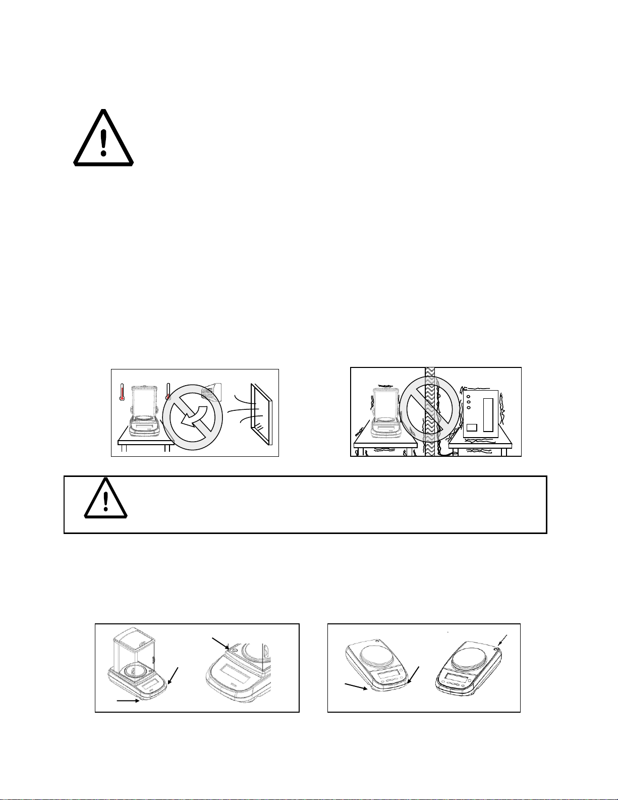
1INSTALLATION INSTRUCTIONS...............................................................................................4
2STORAGE CONDITIONS...............................................................................................................5
3WEIGH PAN ASSEMBLY...............................................................................................................6
4KEYBOARD AND DISPLAY..........................................................................................................6
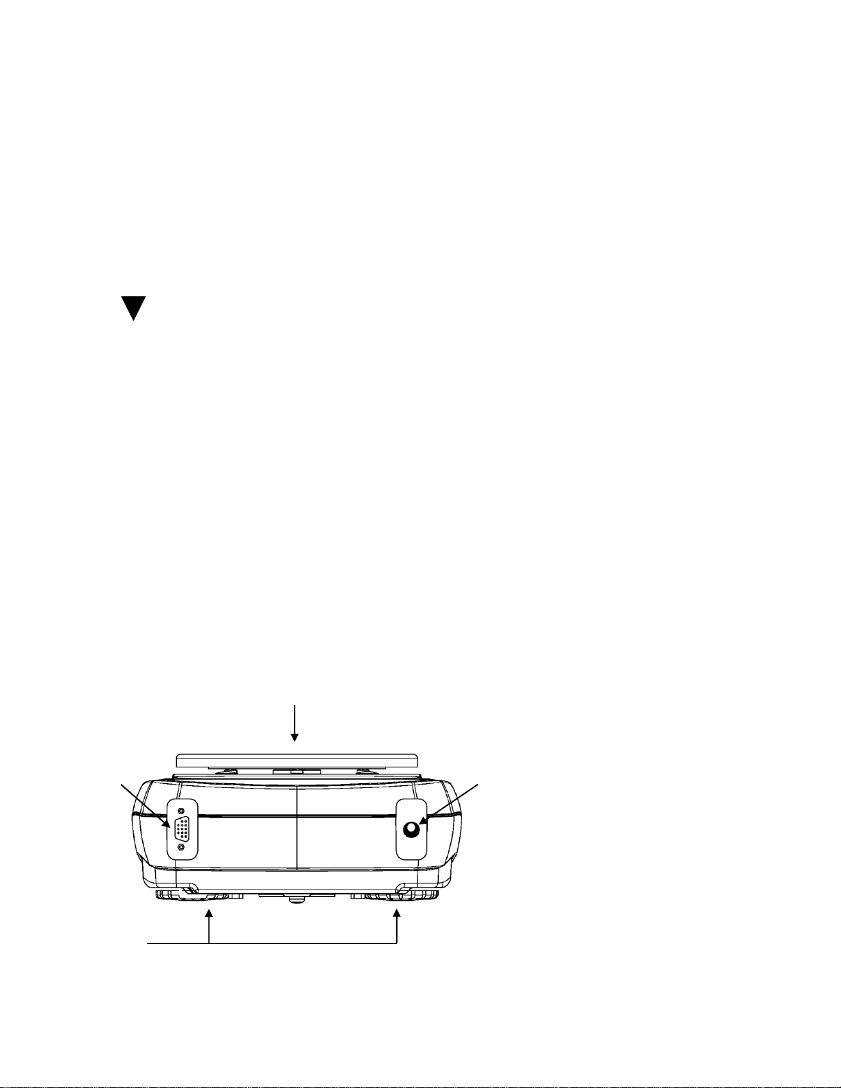
5INPUTS OUTPUTS...........................................................................................................................7
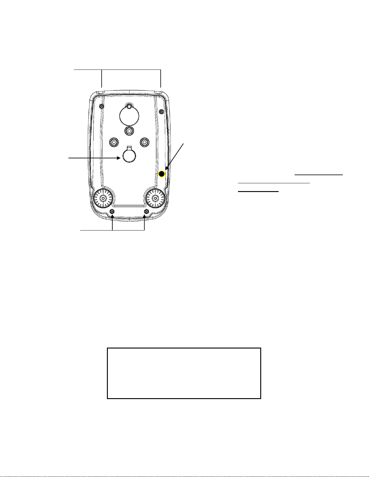
5.1 BALANCE BACK AND UNDERNEATH .............................................................................................7
6WEIGHING........................................................................................................................................8
6.1 STAND BY.....................................................................................................................................9
6.2 SIMPLE WEIGHING.........................................................................................................................9
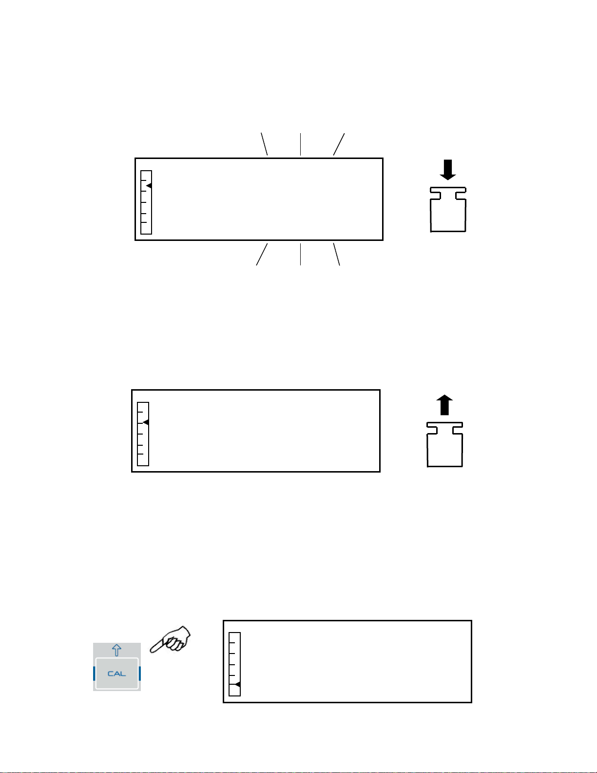
7CALIBRATION.................................................................................................................................9
7.1 BALANCES WITH EXTERNAL CALIBRATION...................................................................................9
7.1.1 External calibration.................................................................................................................9
7.2 BALANCES WITH INTERNAL CALIBRATION..................................................................................11
7.2.1 Internal calibration................................................................................................................11
7.3 VERIFICATION.............................................................................................................................12
8TARE FUNCTION..........................................................................................................................13
8.1 MANUAL TARE FUNCTION...........................................................................................................14
9BALANCE PARAMETERS SETUP MENU...............................................................................15
9.1 WEIGHT UNITS............................................................................................................................16
9.2 SERIAL OUTPUT SETUP ................................................................................................................17
9.3 TRANSMISSION SPEED SELECTION...............................................................................................18
9.4 AUTOZERO FUNCTION.................................................................................................................19
9.5 FILTER SELECTION ......................................................................................................................19
9.6 STABILITY FUNCTION..................................................................................................................20
9.7 CONTRAST ADJUSTMENT............................................................................................................21
9.8 BACKLIGHT REGULATION ...........................................................................................................22
9.9 TIMER-OFF FUNCTION .................................................................................................................23
9.10 DATE AND TIME REGULATION.....................................................................................................23
9.11 LANGUAGE SELECTION ...............................................................................................................25
9.12 CALIBRATION MODE SETTING .....................................................................................................26
9.12.1 Automatic Calibration (AUT-CAL)...................................................................................26
9.12.2 Internal calibration (I-CAL) [locked for verified balances] ............................................27
9.12.3 External calibration (E-CAL) [locked for verified balances]..........................................28
9.12.4 Technical calibration (TEC-CAL) [locked for verified balances]...................................28
9.13 CALIBRATION DATA....................................................................................................................29
10 BALANCE PROGRAMS MENU..................................................................................................30
10.1 PIECE COUNTING FUNCTION........................................................................................................30
Table of Contents:

3
10.1.1 Manual insertion of the average unit weight....................................................................32
10.1.2 Automatic updating of the average unit weight................................................................34
10.2 PROGRAM FOR THE DETERMINATION OF THE DENSITY OF A SOLID OR A LIQUID ........................34
10.2.1 Solid density determination...............................................................................................34
10.2.2 Liquid density determination.............................................................................................36
10.3 FORMULATION FUNCTION...........................................................................................................39
10.3.1 Manual formulation...........................................................................................................39
10.3.2 Formula saving..................................................................................................................40
10.3.3 Formula recall...................................................................................................................42
10.4 MAX-MIN THRESHOLDS FUNCTION. ...........................................................................................45
10.4.1 With both the limits set ......................................................................................................46
10.4.2 With only the lower limit set..............................................................................................46
10.4.3 With only the upper limit set..............................................................................................46
10.5 PERCENTAGE WEIGHING FUNCTION ............................................................................................47
10.5.1 Automatic mode with reference weight.............................................................................47
10.5.2 Mode with manual insertion of the reference weight.......................................................48
10.6 ANIMAL WEIGHING FUNCTION ....................................................................................................49
10.7 MAXIMUM LOAD FUNCTION........................................................................................................50
10.8 GLP FUNCTION (GOOD LABORATORY PRACTICES)....................................................................50
11 RS232 INTERFACE FEATURES.................................................................................................53
11.1 GENERAL FEATURES ...................................................................................................................53
11.2 MAP OF CONNECTOR...................................................................................................................53
11.3 CONNECTON OF THE BALANCE TO THE OPTIONAL ALPHANUMERIC KEYBOARD.........................53
11.4 CONNECTON OF THE BALANCE TO COMPUTER ...........................................................................53
11.4.1 Continuous Transmission mode ........................................................................................55
11.4.2 Ondemand transmission mode..........................................................................................55
11.4.3 Ondemand transmission with G.L.P. ................................................................................57
11.5 CONNECTON OF BALANCE WITH SERIAL PRINTER.......................................................................57
11.5.1 PRINT FORMATS .............................................................................................................58
11.5.2 Generic Printer or TLP 50 printer with G.L.P................................................................59
12 ERROR CODES...............................................................................................................................61
13 MAINTENANCE AND CARE.......................................................................................................62
14 BALANCE TECHNICAL SPECIFICATION........... ERROR! BOOKMARK NOT DEFINED.
15 WARRANTY.....................................................................................................................................63
16 EQUIPMENT DISPOSAL...............................................................................................................63

4
1 Installation instructions
WARNING:
Please carefully read these installation and use instructions before you begin using
your new balance. The product’s safety and accuracy cannot be guaranteed if the
instrument is used in a way that is different from that recommended in this manual.
DO NOT DISCARD THE ORIGINAL PACKAGING MATERIAL. THIS PACKAGING MUST BE
USED IF THE BALANCE NEEDS TO BE RETURNED FOR SERVICE.
▪Remove the balance and its calibration weight (if supplied) from the carton and check for any
visible damage to the instrument.
▪Do not install the balance in environments in which there are drafts, strong temperature
changes, or vibrations.
▪Do not use the balance in potentially explosive environments.
▪The humidity of the environment where the balance is used must be between 45% and
75%.
ATTENTION
For models with internal calibration: remove the protection screw in the
left lower part of the balance (see Section 5)
▪Place the weigh pan support and weigh pan on the balance (see page 6).
▪Level the balance by adjusting the front feet. The leveling bubble will indicate that the
balance is leveled properly.

5
▪Connect the power supply to the power inlet at the back of the balance (see Section 5).
▪Connect the power supply to a nearby outlet, which must be easily accessible. Press the
power button on the right side of the control panel to power on the balance.
▪Balance Warm-up:
▪It is necessary to allow the balance to equilibrate to ambient conditions before use.
Wait at least 8 hours after initially plugging in the analytical balance (0.0001g)
Then calibrate the balance as described in Section 7.
It is strongly suggested not to disconnect power cord from the balance to turn it
off. Use the ON/OFF button to put the balance into stand-by mode when not in
use.
▪Calibrate the balance every time that it is moved to another location.
▪Periodically check the balance’s calibration.
▪Do not drop objects of an excessive weight on the balance weigh pan, as doing so may
damage to the weigh cell mechanism.
▪Service should be carried out by trained personnel, and spare parts used must be original.
Contact your distributor or Accuris Instruments for service.
2 Storage conditions
▪Storage temperature +5 °C to +40°C
▪Storage humidity 45% - 75%.
▪Keep the original balance packaging in case the instrument needs to be shipped for
servicing; disconnect all cables and any accessories to prevent unnecessary damage.
▪Do not expose the balance to extreme temperatures and humidity unnecessarily, and avoid
violent shocks and vibration.

6
3 Weigh pan assembly
4 Keyboard and display
The weigh pan assembly consists of 2 pieces: the pan support
piece is first gently placed onto the weigh cell, and then the
weigh pan is placed gently onto the pan support.
Pan Support
Weigh Pan

7
* Stability indicator
O Zero indicator
%Percent weight
PC Piece counting
Data insertion mode
HUpper threshold
L Lower threshold
DS Density measurement
Ct, ozt, lb, GN, Dwt, kg, mg, g Unit of measurement
5 Inputs outputs
5.1 Balance Rear and Underneath
Figure 1
1. Weigh pan assembly
2. RS232, 9 pin connector for
PC/keyboard and printer
3. Adjustable feet
4 Power supply input
2
3
1
4

8
Figure 2
5. Balance closure screws
6. Weighing hook under the balance
Note: to access, remove the cap
7. Shipping protection screw for auto
calibration motor (only for models
with internal calibration).
ATTENTION: remove this screw
by hand as soon as the balance
is removed from its package
6 Weighing
After connecting the balance to a power outlet, a self-diagnosis of the electronic circuits is
automatically carried out, and when finished “off” is displayed to indicate standby mode:
5
6
5
7
Off

9
6.1 Stand By
From the “STAND BY” state:
▪Press the ON/OFF button to bring the balance to working condition.
▪Press the ON/OFF button again to return to the “STAND BY” state.
6.2 Simple weighing
Place the sample to be weighed on the plate and read the value of the weight on the display as
soon as the asterisk stability symbol ж appears.
7 Calibration
The Accuris Analytical Balance carries out mass measurements using gravity (g). Differences in
geographical regions and altitudes will affect the gravitational acceleration (g).
The balance must therefore be adapted to specific environmental conditions by calibrating to
obtain accurate measurements.
7.1 Balances with external calibration
7.1.1 External calibration
The calibration is carried out through the CAL button.
1. Press the CAL button with the plate unloaded; the word CAL will be displayed.
0.0000
g
01-06-10 13:15:24
-0-
Cal
01-06-10 13:15:24
-0-

10
2. When the value of the calibration weight begins to flash, load the weight indicated by the
display on the plate.
3. The display will stop flashing, indicating the value of the calibration weight with the stability
indicator on.
Once the calibration has been carried out, the calibrated weight will be displayed with the
indication of the current unit of measurement.
4. Remove the calibration weight.
The balance is ready for weighing operations.
NOTE: an error message will be displayed if there is any interference during the calibration process. To
interrupt the calibration process, press the ON/OFF button while the calibration weight indication flashes.
It is also possible to calibrate the balance with a calibration weight greater than the pre-set
calibration weight:
1. Press and hold the CAL button with the weigh pan empty until the beeping stops, and then
release the button. The word “-CAL-“is be shown on the display, followed by the word
“LOAD”, flashing.
200
g
01-06-10 13:15:24
-0-
200.0000
g
01-06-10 13:15:24
-0-
2 Sec
Cal
01-06-10 13:15:24
-0-

11
2. Load a weight that is equal to or greater than the pre-set calibration weight on the plate; the
balance will recognize a weight that is equal to or greater than the calibration weight as valid
provided that it is a whole weight with respect to the most significant figure of the calibration
weight.
E.G.: if the calibration weight is 200 g, it will be possible to calibrate the balance with values
that go from 200g, 300g, 400g up to the upper capacity limit of the balance.
The word “LOAD” on the display will stop flashing; once the calibration has been carried out,
the value of the weight used will be displayed.
3. Remove the calibration weight; the balance is ready for weighing operations.
NOTE: an error message will be displayed if there is some interference during the calibration process. To
interrupt the calibration process, press the ON/OFF button while the calibration weight indication flashes.
7.2 Balances with internal calibration
7.2.1 Internal calibration
In these models the calibration is carried out through an internal automatic system:
1. Press the CAL button with the weigh pan empty.
The display will show the message “CAL” and the balance’s calibration will be carried out
automatically.
200.0000
g
01-06-10 13:15:24
-0-
Load
01-06-10 13:15:24
-0-

12
2. At the end of the calibration, the balance will return to normal weighing conditions.
If the calibration is not completed due to vibrations or drafts, the message “CAL bUT” will be
displayed. Press the CAL button again, and if the problem persists, select external calibration
and contact the supplier.
To switch the calibration mode in these models to external calibration, see section 9.12.1
7.3 Verification
General introduction:
According to EU directive 90/384/EEC balances must be verified if they are used for legally
controlled applications:
a) For commercial transactions if the price of goods is determined by weighing.
b) For the production of medicines in pharmacies as well as for analyses in the
medical and pharmaceutical laboratory.
c) For official purposes.
d) For manufacturing final packages.
For any questions about requirements, please contact your local standards office.
Verification instructions
An EU type approval exists for balances described in their technical data as
verifiable. If a balance is used where obligation to verify exists as described above, it
must verified and re-verified in regular intervals.
Re-verification of a balance is carried out according to the respective national
regulations. The legal regulation of the country where the balance is used must be observed!
After verification the balance is sealed at the indicated positions.
0.0000
g
01-06-10 13:15:24
-0-
Cal
01-06-10 13:15:24
-0-

13
Verification of the balance is invalid without the "seal".
Balances with a verification requirement must be taken out of operation if:
•The weighing result of the balance is outside the error limit.
Therefore, in regular intervals load balance with known test weight (ca.
1/3 of the max. load) and compare with displayed value.
•The reverification deadline has been exceeded.
8 Tare function (example using a weighing container)
1. The relative weight of the weighing container will be shown on the display.
2. Press the TARE button. The word “Tare”will be displayed.
21.3140
g
01-06-10 13:15:24
Position of the seal mark for Verified balances models
Tare
01-06-10 13:15:24

14
3. Once stability has been achieved, the zero value “0.0000” will be displayed. In case stability
is not achieved due to drafts, vibrations, or other types of disturbance, the dashes will
continue to be displayed.
4. Place the objects to be weighed in the container. Read the value of the net weight on the
display.
8.1 Manual tare function
This function allows a tare value to be entered manually.
1. Press and hold the TARE button with the weigh pan empty until the beeping stops, and then
release the button.
2. “Manual tare” will be shown on the display:
3. Now insert the desired tare value using the CAL and MENU buttons to increase and
decrease the number, while pressing the TARE button to pass to the next number. During
the entering phase, holding down the TARE button allows you to delete the inserted value.
0.0000
g
01-06-10 13:15:24
-0-
231.1400
g
01-06-10 13:15:24
2 Sec
0.0000
g
01-06-10 13:15:24
-0-
Manual tare

15
Setup Menù
- Weight Units
- Serial output
- Baud rate
- Auto zero
- Filter
Setup Menù
- Weight Unit
- Serial output
- Baud rate
- Auto zero
- Filter
4. After having entered the desired value, press the PRINT button to confirm it. The value will
remain in memory until the TARE button is pressed, or the instrument is disconnected from
the power supply
9 Balance parameters setup menu
1. Press and hold the MENU button with the plate empty until the beeping stops, and then
release the button.
2. The following writing will be shown on the display:
3. Now use the CAL and MENU buttons to navigate forward or backward in the parameters
menu.
…
…
90.0000
g
01-06-10 13:15:24
-0-
Manual tare
Setup Menu
- Stability
- Contrast Adjustment
- Backlighting
- Timer off
- Date and time
Setup Menu
2 Sec

16
…
…
…
4. Position the cursor on the desired parameter and press the PRINT button to confirm the
selection.
5. Press the ON/OFF button to exit from the menu or select the return function and press the
PRINT button.
9.1 Weight Units
The weight units with which the balance will weigh can be selected.
1. Set the weight units parameter as described in chapter 10.
The currently set weight units will be shown on the display:
2. Now by pressing the MENU or CAL button it will be possible to scroll through the weight units
forward or backward.
3. Then press the PRINT button to confirm the desired weight units.
- Language
- Calibration mode
- Calibration data
Grams
Weight Units

17
**not available in verified balances
4. After having selected the desired weight unit, the screen relative to the menu of balance
parameters will be displayed again. It will now be possible to select another parameter or
return to weighing mode by pressing the ON/OFF button.
By returning to the weighing mode in the right part of the display, the symbol of the selected
weight unit will be displayed.
9.2 Serial output setup
Different data transmission devices and modes can be selected.
1. Select the serial output parameter as described in paragraph 10.
The currently set transmission mode will be shown on the display:
2. Now by pressing the MENU or CAL button it will be possible to scroll through the serial output
MENU forward or backward.
3. Then press the PRINT button to confirm the desired transmission mode.
SYMBOL
UNIT OF
MEASUREMENT
CONVERSION
FACTOR
1 g =
g
GRAMS
1.
ct
CARATS
5.
oz
OUNCES**
0.035273962
lb
POUNDS**
0.0022046226
Dwt
PENNYWEIGHTS**
0.643014931
ozt
TROY OUNCE**
0.032150747
GN
GRAINS**
15.43235835
tl1
HONG KONG
TAEL**
0.02671725
tl2
SYNGAPORE
TAEL**
0.02646063
tl3
TAIWAN TAEL**
0.02666666
mo
MOMME**
0.2667
Continuous
Serial output

18
The different transmission modes are illustrated below:
NOTE: transmission speed selection (paragraph 9.3)
4. After having selected the desired transmission mode, the screen relative to the balance
parameters menu will be displayed again. It will now be possible to select another parameter
or return to weighing mode by pressing the ON/OFF button.
9.3 Transmission speed selection
Different data transmission speeds can be selected.
1. Select the baud rate parameter as described in paragraph 10.
The currently set transmission speed will be shown on the display:
2. Select the serial data transmission speed (1200-2400-4800-9600 baud). By pressing the
MENU or CAL button you can scroll the different transmission speeds forward or backward;
then confirm the choice with the PRINT button.
3. After having selected the desired transmission speed, the screen relative to the balance
TRANSMISSION MODE
FEATURES
Continuous
Transmits the weight data in a continuous way
On demand
Transmits the weight data only when the PRINT button is pressed
Generic printer
The weight data is printed only when the Busy command is active
Tlp50 printer
The weight data is printed only if the Tlp50 model printer is
connected
Upon request - Glp
Transmits the weight data and the Glp information only when the
PRINT button is pressed
Generic printer - Glp
The weight data and the Glp information are printed only when the
Busy command is active
Tlp –Glp printer
The weight data and the Glp information are printed only if the Tlp50
model printer is connected
1200 Baud
Baud rate

19
parameter menu will be displayed again. It will now be possible to select another parameter
or return to weighing mode by pressing the ON/OFF button.
9.4 Autozero function
Autozero is a correction from a possible deviation from zero.
Different autozero levels can be selected.
1. Select the autozero parameter as described in chapter 10.
The currently set autozero parameter will be shown on the display:
2. Select the desired autozero level. By pressing the MENU or CAL button it will be possible to
scroll through the various levels forward or backward; then confirm your choice with the
PRINT button.
*locked in verified balances
3. After having selected the desired autozero, the screen relative to the balance parameters
menu will be displayed again. It will now be possible to select another parameter or return to
weighing mode by pressing the ON/OFF button.
9.5 Filter selection
The balance can be adapted to different environmental conditions thanks to the selection of three
different filters:
1. Select the filter parameter as described in paragraph 10.
AUTOZERO MENU
AUTOZERO LEVEL
Autozero off
Autozero off
Autozero 1
Light autozero
Autozero 2*
Average autozero
Autozero 3*
Heavy autozero
Autozero 3E*
Heavy full-scale autozero
Autozero 2
Auto zero

20
The currently set filter type will be shown on the display:
2. Select the desired filter level. Pressing the MENU or CAL button it will be possible to scroll
through the various levels forward or backward; then confirm your choice with the PRINT
button.
3. After having select the desired filter level, the screen relative to the balance parameters menu
will be displayed again. It will now be possible to select another parameter or return to
weighing mode by pressing the ON/OFF button.
9.6 Stability function
The stability symbol will appear on the display when the weight is stable within a defined interval.
1. Select the stability parameter as described in paragraph 10.
The currently set type of stability will be shown on the display:
FILTER MENU
FILTER LEVEL
Filter 1
Use this filter level in stable environmental conditions and for use of
the instrument in filling or dosing mode
Filter 2
Use this filter level when the environmental conditions are not stable
Filter 3
Use this filter level when the environmental conditions are
particularly unstable
Filter 2
Filter
Stability 2
Stability
This manual suits for next models
4
Table of contents
Other Accuris Scale manuals
Popular Scale manuals by other brands

Right Weigh
Right Weigh 202-DDG-01 Installation and operation manual

Westinghouse
Westinghouse WKS26 user manual

Adam Equipment
Adam Equipment LBK Series manual

STARFRIT
STARFRIT Balance Instructions for use

Soehnle Professional
Soehnle Professional 7700 operating instructions

Salter
Salter 9069 PK3R Instructions and guarantee