Accutach GM Steering Wheel Button Box User manual

GM Steering Wheel Button Box
Installation Guide
Rev. 1.0
© 2019 Accutach Co.
www.accutach.com
Thank you for purchasing the Accutach Co. General Motors Steering Wheel Button Box. It is designed to allow you
to repurpose the audio and/or cruise control buttons on your stock GM steering wheel to control other accessories.
Supported GM cars include: 1997-2001 Camaro, 1995-2002 Firebird, 2007-2013 Corvettes, 2010-2015 Camaros
and other GM cars, trucks and SUVs of those vintages. See the list of known compatible cars in the following
sections of this document. This box may be compatible with other models of GM vehicles.
WARNINGS and DISCLAIMERS:
You use this product at your own risk. Accutach Company is not responsible for personal injury or property damage
through the use of this product. While it is possible to use a switch in the steering wheel control wire to switch the
steering wheel button function from radio/cruise control to accessory control and back again, Accutach Company
strongly recommends that users permanently change the button functions from radio/cruise control to control of your
accessory. If you choose to use a switch against our recommendations be careful make sure you know how the
switch is set prior to pressing any steering wheel button. You’d hate to activate a line lock at road speeds while
trying to adjust the radio.
Do not touch the air bag wiring as you modify the radio control wiring near the steering column. Make sure you
disconnect the battery before doing any electrical work described in this installation guide and follow the air bag
safety recommendations in the GM shop manual.
We strongly recommend making wire connections with solder & shrink tubing, although properly made crimp splices
can also be reliable. We do not recommend using “Scotch Lock” style connections for our products. Do not use the
“twist & tape” method of connecting wires.
Before you begin:
You will need to identify a switched battery voltage power supply wire to splice into for power for the Corvette
Steering Wheel Button Box, and you will need a good chassis ground to ground the unit.
You will also need to locate a suitable place to install the unit inside of the vehicle’s cabin, most likely under the
dash or in the console near the shifter. It is not intended for use in the engine compartment or anywhere outside of
the cabin. If you wish to create a custom mounting bracket out of ABS plastic you can glue it to the ABS box with
standard ABS cement from a hardware store.
Page 1

Before you begin (Cont.):
You will need to read the service manual for your vehicle to learn how to safely disable the air bag system. Failure
to properly disable the air bag system could lead to injury or death if the air bag accidentally deploys while you are
installing the steering wheel button box.
You will need to locate the steering wheel power and signal wires coming down from the clockspring mechanism for
your car. Here are the wire colors for some of the more popular GM vehicles. If your car is not on this list, you will
need to contact Accutach Co..
95-02 Firebird,
97-01 Camaro
92-99 Bonneville
98-99 Riviera
Power: YEL
Signal: DK BLU
07-13 Corvette
Power: PPL/WHT
Signal: DK BLU
----------------------------------------------------------------------------------------------------------------------------------------------------------
10-15 Camaro,
11-16 Cruze,
14-16 Malibu,
11-15 Volt,
Power: YEL
Signal (Audio): LT GRN
Signal (Cruise): GRY
The Accutach Co. GM Steering Wheel Button Box has 5 modes of operation. One mode repurposes the steering
wheel buttons for Firebirds, older Camaros, Corvettes and the other vehicles above without cruise control signals.
The remaining 4 modes of operation provide 4 different ways of remapping 8 of the buttons on 2010-2015 Camaros
and the other vehicles above with cruise control signals. If your vehicle is not on the lists above, please contact
Accutach Co. to see if your GM vehicle is also supported.
You will need to plan your button mapping The GM Steering Wheel Button Box has 8 relays and 8 pairs of colored
output wires. After installation, when you press a button on the steering wheel, the relay associated with that button
will close, connecting the associated colored wire pair together.
Firebirds, older Camaros and cars with the same steering wheel switches have 8 audio pushbuttons to repurpose,
while the Corvettes have 7 audio pushbuttons. You will need to decide which buttons will control which accessories.
Accutach Co. also supplies auxiliary toggle and on/off boxes if a simple pushbutton switch action is not adequate for
you application.
2010-2015 Camaros and other cars with the same switch modules have 10 buttons and one switch. The cruise
control group consists of the switch and 3 buttons. The cruise control ON switch must be set to On for the other
cruise control buttons to work. The audio group consists of 7 buttons. The Accutach Co. Steering Wheel Button
Box only has 8 relays, so only a subset of the steering wheel functions can be mapped in any mode. Please read
the 2010-2015 Camaro operating mode pages so you can decide which button remapping mode you will want to
use for your car.
07-13 Chevy Silverado, 07-13 Chevy Avalanche,
07-14 Chevy Suburban, 07-14 Chevy Tahoe,
07-13 GMC Sierra, 07-14 GMC Yukon, 08-09 Hummer H2,
07-14 Cadillac Escalade
Power: PNK
Signal (Audio): LT GRN
Signal (Cruise): GRY
03-06 Chevy Avalanche, 03-06 Chevy Suburban, 03-06 Chevy Tahoe, 03-06
GMC Sierra, 03-06 GMC Yukon, 03-07 Hummer H2, 03-06 Cadillac Escalade
Power: DK BLU
Signal: LT GRN
03-06 Chevy Silverado
Power: LT GRN
Signal: DK BLU
04-09 Chevy Trailblazer, 05-08 Isuzu Ascender,
04-07 Buick Rainier
Power: WHT
Signal: LT GRN

Mode 0: (2010-2015 Camaro, etc.) Right handed
Mode 0 is selected by leaving the WHT/ORN & WHT/BLK wires disconnected. Put shrink tubing over the ends of
these wires to ensure they don’t accidentally short to anything.
The other vehicles with the cruise control signal have the same buttons but with different functions. The button
names are: Camaro Suburban, Silverado, Avalanche, Tahoe, Sierra, Yukon, H2, Escalade
VOL+ MUTE
VOL- VOL-
SEEK+ VOL+
SEEK- PREVIOUS
SOURCE NEXT
VOICE SOURCE
MUTE SEEK
CANCEL CANCEL
SET-SET-
RES+ RES+
ON ON
Mode 1: (2010-2015 Camaro, etc.) Most right handed mode
Mode 1 is selected by leaving the WHT/BLK wire disconnected. Put shrink tubing over the end of the WHT/BLK
wire to ensure it doesn’t accidentally short to anything. Ground the WHT/ORN wire.
Page 2
Yellow
Pair
Gray
Pair
Orange
Pair
Green
Pair
Purple
Pair
WHT/BRN
Pair
White
Pair
(ON Switch)
Brown
Pair
ON switch must be On for
the other cruise control
buttons to be enabled.
Yellow
Pair
Gray
Pair
Orange
Pair
White
Pair
Purple
Pair
WHT/BRN
Pair
Brown
Pair
Green
Pair

Page 3
Mode 2: (2010-2015 Camaro, etc.) Even handed
Mode 2 is selected by leaving the WHT/ORG wire disconnected. Put shrink tubing over the end of the WHT/ORG
wire to ensure it doesn’t accidentally short to anything. Ground the WHT/BLK wire.
Mode 3: (2010-2015 Camaro, etc.) Right handed
Mode 3 is selected by grounding the WHT/ORN & WHT/BLK wires.
Note that the 2010-2015 Camaro cruise control buttons include an ON switch. That switch is a toggle switch, but it
is not a momentary-on switch. When you press the ON switch, it stays on until you press the bottom side of the ON
switch, which turns it Off. The other cruise control buttons are enabled only when the ON switch is On. They are
disabled when it is Off. The GM Steering Wheel Button Box can detect when the ON button is on or off, so that
switch can also control an output.
Yellow
Pair
Gray
Pair
Orange
Pair
Green
Pair
Purple
Pair
WHT/BRN
Pair
White
Pair
(ON Switch)
Brown
Pair
ON switch must be On for
the other cruise control
buttons to be enabled.
Yellow
Pair
Gray
Pair
Orange
Pair
White
Pair
Purple
Pair
WHT/BRN
Pair
ON Switch
must be On
for the
CANCEL
switch to be
enabled.
Brown
Pair
Green
Pair

Page 4
Mode 4: (1995-2002 Firebird, 1997-2001 Camaro, etc.)
Mode 4 is selected by leaving the WHT/ORN & WHT/BLK wires disconnected. Put shrink tubing over the ends of
these wires to ensure they don’t accidentally short to anything. Ground the WHT/RED wire.
Mode 4: (2007-2013 Corvette)
Note that 2007-2008 Corvettes only have the 5 right hand buttons. Also note that not all 2009-2013 Corvettes have
the 2 left hand Bluetooth buttons, so Corvettes only have 5 to 7 buttons to repurpose.
The older vehicles without the cruise control signal have the same buttons but with different functions. The button
names are:
Silverado, Trailblazer,
Suburban, Avalanche,
Camaro, Tahoe, Envoy,
Firebird Corvette Sierra, Yukon Impala Century
VOL+ VOL+ VOL+ VOL+ VOL+
VOL- VOL- VOL- VOL- VOL-
PLAY NEXT SEEK+ MODE SOURCE
MUTE PREVIOUS SEEK- MUTE MUTE
SEEK+ PRESET 1-6 VOICE SEEK+ SEEK+
SEEK- VOICE PROG SEEK-SEEK-
AM/FM PHONE SOURCE+ SCAN SCAN
PRESET SOURCE- PRESET AM/FM
Yellow
Pair
Gray
Pair
Orange
Pair
Green
Pair
Purple
Pair
WHT/BRN
Pair
White
Pair
Brown
Pair
Yellow
Pair
Gray
Pair
Orange
Pair
Green
Pair
Purple
Pair
White
Pair
Brown
Pair

Locating the Radio/Cruise Control Signal Wires
The 07-13 Corvette is shown here as an example. Refer to your vehicle’s service manual if you are unsure of how
to acces the steering column wiring in your vehicle.
You will need to remove the plastic cover under the drivers side dash to gain access to the wiring in the steering
column.
The plastic cover under the driver’s side dash is held in place with two screws, four clips and two hooks. Remove
the two screws using a Torx T10 driver:
Carefully pull the plastic cover down from the bottom so that it can pivot on the hooks at the top of the panel as the
clips disengage. Here is a picture of the clips:
Clips
Page 5
Torx T10 Screw Torx T10 Screw
Clips

Here is a photo with the panel removed:
Find connector C231 behind the metal panel. Slide it left to release it in order to get access to the steering wheel
control signal wire. It should look like this:
Make sure you DO NOT expose the air bag connector instead.
Carefully get access to the Steering Wheel Control Signal and Radio Control Supply Voltage wires.
95-02 Firebird, 97-01 Camaro, 92-99 Boneville, 98-99 Buick Riviera, etc.
Power: YEL
Signal: DK BLU
05-13 Corvette
Power: PPL/WHT
Signal: DK BLU
10-15 Camaro, 11-16 Cruze, 14-16 Malibu, 11-15 Volt, etc.
Power: YEL
Signal: LT GRN (Audio)
Signal: GRY (Cruise)
Find the Dark
Blue Steering
Wheel Control
Signal wire
and the
Purple/White
Radio Control
Supply Voltage
wire in a
Corvette
Page 6
Connector
C231

Installing the GM Steering Wheel Button Box
At this point, you should have unhooked the battery and followed the service manual process for disabling the air
bag system. If you have not, do that now.
Once you have located the signal and power lines below the clocksping mechanism, cut them both. Make sure that
the power wires coming from the audio/cruise control modules are covered with shrink tubing and secured so they
can’t short to anything including the vehicle body. If a power wire is powered and the power wire shorts out, you
may destroy your audio system or your body control module.
This is a good time to test your steering wheel button circuit to make sure it is working properly prior to repurposing.
Put an ohmmeter across the Power and Signal wires going up into the clockspring mechanism. With each button
pressed one at a time, you should see resistance values on the ohmmeter that are within 5% of these resistances:
97-01 Camaro, 03-06 Silverado,
95-02 Firebird, 04-09 Trailblazer, 00-05 Impala Resistance
Corvette etc. etc.
VOL+ VOL+ VOL+ VOL+ 1270 Ohms
VOL- VOL- VOL- VOL- 1564 Ohms
NEXT PLAY SEEK+ MODE 1912 Ohms
PREVIOUS MUTE SEEK- MUTE 2387 Ohms
PRESET 1-6 SEEK+ VOICE SEEK+ 3102 Ohms
VOICE SEEK- PROG SEEK-4282 Ohms
PHONE AM/FM SOURCE+ SEEK TYPE 6652 Ohms
None PRESET SOURCE- PRESET 13612 Ohms
10-15 Camaro, 07-13 Silverado, 07-14 Suburban,
11-16 Cruze, 07-14 Tahoe, 07-13 Avalanche,
14-16 Malibu, 07-13 Sierra 07-14 Yukon,
11-15 Volt 08-09 H2, 07-14 Escalade
Audio Buttons Audio Buttons Resistance
VOL+ MUTE 1210
VOL- VOL- 1511
SEEK+ VOL+ 1923
SEEK- PREVIOUS 2410
SOURCE NEXT 3014
VOICE SOURCE 3820
MUTE SEEK 5320
Cruise Buttons Cruise Buttons Resistance
OFF OFF Open Circuit
ON ON 6805
RES+ RES+ 3795
SET-SET- 2325
CANCEL CANCEL 1500
If you don’t see resistances near these, debug the steering wheel switches and the wiring from the switches through
the clockpring mechanism to the cut wire ends before continuing with the installation.

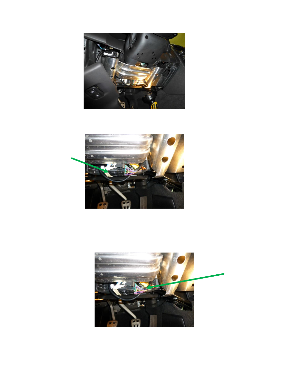
After you have validated the switches and wiring, splice the Power wire going up into the clockspring mechanism to a
wire that you run to the same ground you use for the Steering Wheel Box ground. For the vehicles without cruise
control buttons, splice the Blue wire from the Accutach Steering Wheel Button Box to the Signal wire going up into
the clockspring mechanism.
For vehicles with cruise control buttons, splice the Blue wire from the Accutach Steering Wheel Button Box to the
Audio Signal wire going up into the clockspring mechanism. Splice the WHT/RED wire from the Accutach Steering
Wheel Button Box to the Cruise Control Signal wire going up into the clockspring mechanism.
Use shrink tubing to insulate the other side of the power wire that goes to the OEM audio system. Do not leave the
OEM audio system in the circuit or the Steering Wheel Button Box will not work.
It is possible to configure the output of the Steering Wheel Button Box to simulate the steering wheel button circuit
for some of the buttons. This will allow you to repurpose some of the buttons for custom use while leaving the rest of
the buttons with the OEM function. Please contact Accutach Co. for applications assistance if you want to do that.
Accutach Co. strongly recommends that you permanently repurpose your steering wheel buttons. However, it is
possible to install a switch that will allow you to switch between “Race Mode” where the steering wheel buttons
control your racing accessories and “Street Mode” where your steering wheel buttons control the OEM functions. If
you use a switch like this, you do so at your own risk. If you press a button thinking it will control one accessory and
another is activated, there is danger of damage to your vehicle, injury or even death. For example, you would not
want to activate a transbrake at highway speeds thinking you are activating cruise control. Such an example would
have avery bad end.
If you choose to use a switch to retain the use of the radio control function of your vehicle (against our
recommendations), then we recommend that you add an extra pole to the switch to add an indicator that lights when
you are in Race Mode (Not Included).
Since the Steering Wheel Button Box requires that the common wire to the steering wheel be grounded, you must
use a “break-before-make” type of switch. This is due to the fact that you will need to change the OEM Power wire
into a ground wire and a “make-before-break” switch will cause a momentary short of power to ground. The
switches recommended in this document are break-before-make type.
You will need a 3PDT switch to switch a single group of buttons. If you want to switch both the audio and cruise
functions, you will need a 4PDT switch.
Accutach Co. recommends the following switches (Not Included):
3PDT: NKK M2032TYW01-JA, Digikey part number M2032TYW01-JA-ND
4PDT: NKK M2042TNW01-DA, Digikey part number 360-2276-ND
To repurpose one button group, wire a 3PDP switch’s common connections to a ground for the Race Mode Indicator,
the Power wire and the Signal wire going to the steering wheel. Wire one side of the 3PDT switch to the OEM
Power and Signal wires, leaving the indicator not connected. Wire the other side of the 3PDT switch so that the
Power wire going to the steering wheel gets connected to ground and the Signal wire going to the steering wheel
gets connected to the Steering Wheel Button Box input signal wire:
3PDT
12V
Race Mode
Indicator
OEM Power Wire
Power Wire to
Steering Wheel
Signal Wire to
Steering Wheel OEM Signal Wire
Steering Wheel Button Box Signal Wire

To repurpose one button group, wire a 4PDP switch’s common connections to a ground for the Race Mode Indicator,
the Power wire and the Signal wire going to the steering wheel. Wire one side of the 4PDT switch to the OEM
Power and Signal wires, leaving the indicator not connected. Wire the other side of the 4PDT switch so that the
Power wire going to the steering wheel gets connected to ground, the Audio Signal wire going to the steering wheel
gets connected to the Steering Wheel Button Box Blue input signal wire and the Cruise Control Signal wire going to
the steering wheel gets connected to the Steering Wheel Button Box WHT/RED input signal wire:
The following section describe how to connect the Accutach Co. Steering Wheel Button Box in a number of popular
GM vehicles.
4PDT
12V
Race Mode
Indicator
OEM Power Wire
Power Wire to
Steering Wheel
Audio Signal Wire
to Steering Wheel OEM Audio Signal Wire
Blue Steering Wheel Button Box Signal Wire
Cruise Signal Wire
to Steering Wheel OEM Cruise Signal Wire
WHT/RED Steering Wheel Button Box Signal Wire

07-13 Corvette (Mode 4)
Here is a schematic diagram of how to connect the Accutach GM Steering Wheel Button Box to a Corvette with a
3PDT switch (Mode 4):
GM Steering Wheel
Button Box
Audio System
DK BLU
x
Cut these wires
Switched
Battery Voltage
Input
Blue
Ground
Black
Power
Red
Output
Green
Purple
Purple
Green
Yellow
Yellow
Orange
Orange
Gray
Gray
“VOL+” Momentary
Pushbutton Switch
“PRESET 1-6” Momentary
Pushbutton Switch
“NEXT” Momentary
Pushbutton Switch
“PREVIOUS” Momentary
Pushbutton Switch
“VOL-” Momentary
Pushbutton Switch
Each Steering Wheel Button Box output is
rated to 125V and 1A. Switching of larger
signals will require an additional external
relay
Brown
Brown “PHONE” Momentary
Pushbutton Switch
White
White “VOICE” Momentary
Pushbutton Switch
PPL/WHT
x
DK BLU PPL/WHT
WHT/BRN
WHT/BRN Not used
GM Steering Wheel
Button Box
Audio System
DK
BLU Input
Blue
Ground
Black
Power
Red
Output
DK BLU
Green
Purple
Purple
Green
Yellow
Yellow
Orange
Orange
Gray
Gray
Each Steering Wheel Button Box output is
rated to 120V and 1A. Switching of larger
signals will require an additional external
relay
Brown
Brown
White
White
PPL/WHT
PPL/WHT
Switched
Battery Voltage
12V
Race Mode
Indicator
3PDT
“VOL+” Momentary
Pushbutton Switch
“PRESET 1-6” Momentary
Pushbutton Switch
“NEXT” Momentary
Pushbutton Switch
“PREVIOUS” Momentary
Pushbutton Switch
“VOL-” Momentary
Pushbutton Switch
“PHONE” Momentary
Pushbutton Switch
“VOICE” Momentary
Pushbutton Switch
Not used
WHT/BRN
WHT/BRN
Page 11
Input
WHT/RED
Input
WHT/RED

95-02 Firebird, 97-01 Camaro, 92-99 Bonneville, 98-99 Riviera (Mode 4)
Here is a schematic diagram of how to connect the Accutach GM Steering Wheel Button Box to an 95-02 Firebird,
97-01 Camaro, 92-99 Bonneville or 98-99 Riviera with a 3PDT switch (Mode 4):
Page 12
GM Steering Wheel
Button Box
Audio System
DK BLU
x
Cut these wires
Switched
Battery Voltage
Input
Blue
Ground
Black
Power
Red
Output
Green
Purple
Purple
Green
Yellow
Yellow
Orange
Orange
Gray
Gray
“VOL+” Momentary
Pushbutton Switch
“SEEK+” Momentary
Pushbutton Switch
“PLAY” Momentary
Pushbutton Switch
“MUTE” Momentary
Pushbutton Switch
“VOL-” Momentary
Pushbutton Switch
Each Steering Wheel Button Box output is
rated to 125V and 1A. Switching of larger
signals will require an additional external
relay
Brown
Brown “AM/FM” Momentary
Pushbutton Switch
White
White “SEEK-” Momentary
Pushbutton Switch
YEL
x
SK BLU YEL
WHT/BRN
WHT/BRN “PRESET” Momentary
Pushbutton Switch
GM Steering Wheel
Button Box
Audio System
DK
BLU Input
Blue
Ground
Black
Power
Red
Output
DK BLU
Green
Purple
Purple
Green
Yellow
Yellow
Orange
Orange
Gray
Gray
Each Steering Wheel Button Box output is
rated to 120V and 1A. Switching of larger
signals will require an additional external
relay
Brown
Brown
White
White
PPL/WHT
PPL/WHT
Switched
Battery Voltage
12V
Race Mode
Indicator
3PDT
“VOL+” Momentary
Pushbutton Switch
“PRESET 1-6” Momentary
Pushbutton Switch
“NEXT” Momentary
Pushbutton Switch
“PREVIOUS” Momentary
Pushbutton Switch
“VOL-” Momentary
Pushbutton Switch
“PHONE” Momentary
Pushbutton Switch
“VOICE” Momentary
Pushbutton Switch
Not used
WHT/BRN
WHT/BRN
Input
WHT/RED
Input
WHT/RED

03-06 Avalanche, 03-06 Suburban, 03-06 Tahoe, 03-06 Sierra, 03-06 Yukon,03-07 H2, 03-06 Escalade
(Mode 4)
Here is a schematic diagram of how to connect the Accutach GM Steering Wheel Button Box to an 03-06
Avalanche, 03-06 Suburban, 03-06 Tahoe, 03-06 Sierra, 03-06 Yukon,03-07 H2 or 03-06 Escalade with a 3PDT
switch (Mode 4):
Page 13
GM Steering Wheel
Button Box
Audio System
DK BLU
x
Cut these wires
Switched
Battery Voltage
Input
Blue
Ground
Black
Power
Red
Output
Green
Purple
Purple
Green
Yellow
Yellow
Orange
Orange
Gray
Gray
“VOL+” Momentary
Pushbutton Switch
“VOICE” Momentary
Pushbutton Switch
“SEEK+” Momentary
Pushbutton Switch
“SEEK-” Momentary
Pushbutton Switch
“VOL-” Momentary
Pushbutton Switch
Each Steering Wheel Button Box output is
rated to 125V and 1A. Switching of larger
signals will require an additional external
relay
Brown
Brown “SOURCE+” Momentary
Pushbutton Switch
White
White “PROG” Momentary
Pushbutton Switch
LT GRN
xDK BLULT GRN
WHT/BRN
WHT/BRN “SOURCE-” Momentary
Pushbutton Switch
GM Steering Wheel
Button Box
Audio System
LT
GRN Input
Blue
Ground
Black
Power
Red
Output
LT GRN
Green
Purple
Purple
Green
Yellow
Yellow
Orange
Orange
Gray
Gray
Each Steering Wheel Button Box output is
rated to 120V and 1A. Switching of larger
signals will require an additional external
relay
Brown
Brown
White
White
DK BLU
DK BLU
Switched
Battery Voltage
12V
Race Mode
Indicator
3PDT
WHT/BRN
WHT/BRN
“VOL+” Momentary
Pushbutton Switch
“VOICE” Momentary
Pushbutton Switch
“SEEK+” Momentary
Pushbutton Switch
“SEEK-” Momentary
Pushbutton Switch
“VOL-” Momentary
Pushbutton Switch
“SOURCE+” Momentary
Pushbutton Switch
“PROG” Momentary
Pushbutton Switch
“SOURCE-” Momentary
Pushbutton Switch
Input
WHT/RED
Input
WHT/RED

03-06 Silverado (Mode 4)
Here is a schematic diagram of how to connect the Accutach GM Steering Wheel Button Box to an 03-06 Silverado
with a 3PDT switch (Mode 4):
Page 14
GM Steering Wheel
Button Box
Audio System
DK BLU
x
Cut these wires
Switched
Battery Voltage
Input
Blue
Ground
Black
Power
Red
Output
Green
Purple
Purple
Green
Yellow
Yellow
Orange
Orange
Gray
Gray
“VOL+” Momentary
Pushbutton Switch
“VOICE” Momentary
Pushbutton Switch
“SEEK+” Momentary
Pushbutton Switch
“SEEK-” Momentary
Pushbutton Switch
“VOL-” Momentary
Pushbutton Switch
Each Steering Wheel Button Box output is
rated to 125V and 1A. Switching of larger
signals will require an additional external
relay
Brown
Brown “SOURCE+” Momentary
Pushbutton Switch
White
White “PROG” Momentary
Pushbutton Switch
LT GRN
x
DK BLU LT GRN
WHT/BRN
WHT/BRN “SOURCE-” Momentary
Pushbutton Switch
GM Steering Wheel
Button Box
Audio System
Input
Blue
Ground
Black
Power
Red
Output
LT GRN
Green
Purple
Purple
Green
Yellow
Yellow
Orange
Orange
Gray
Gray
Each Steering Wheel Button Box output is
rated to 120V and 1A. Switching of larger
signals will require an additional external
relay
Brown
Brown
White
White
DK
BLU
DK BLU
Switched
Battery Voltage
12V
Race Mode
Indicator
3PDT
WHT/BRN
WHT/BRN
“VOL+” Momentary
Pushbutton Switch
“VOICE” Momentary
Pushbutton Switch
“SEEK+” Momentary
Pushbutton Switch
“SEEK-” Momentary
Pushbutton Switch
“VOL-” Momentary
Pushbutton Switch
“SOURCE+” Momentary
Pushbutton Switch
“PROG” Momentary
Pushbutton Switch
“SOURCE-” Momentary
Pushbutton Switch
LT GRN
Input
WHT/RED
Input
WHT/RED

04-09 Trailblazer, 05-08 Ascender, 04-07 Rainier (Mode 4)
Here is a schematic diagram of how to connect the Accutach GM Steering Wheel Button Box to an 04-09
Trailblazer, 05-08 Ascender or 04-07 Rainier with a 3PDT switch (Mode 4):
Page 15
GM Steering Wheel
Button Box
Audio System
Input
Blue
Ground
Black
Power
Red
Output
LT GRN
Green
Purple
Purple
Green
Yellow
Yellow
Orange
Orange
Gray
Gray
Each Steering Wheel Button Box output is
rated to 120V and 1A. Switching of larger
signals will require an additional external
relay
Brown
Brown
White
White
WHT
WHT
Switched
Battery Voltage
12V
Race Mode
Indicator
3PDT
WHT/BRN
WHT/BRN
“VOL+” Momentary
Pushbutton Switch
“VOICE” Momentary
Pushbutton Switch
“SEEK+” Momentary
Pushbutton Switch
“SEEK-” Momentary
Pushbutton Switch
“VOL-” Momentary
Pushbutton Switch
“SOURCE+” Momentary
Pushbutton Switch
“PROG” Momentary
Pushbutton Switch
“SOURCE-” Momentary
Pushbutton Switch
LT
GRN
Input
WHT/RED
GM Steering Wheel
Button Box
Audio System
LT GRN
x
Cut these wires
Switched
Battery Voltage
Input
Blue
Ground
Black
Power
Red
Output
Green
Purple
Purple
Green
Yellow
Yellow
Orange
Orange
Gray
Gray
“VOL+” Momentary
Pushbutton Switch
“VOICE” Momentary
Pushbutton Switch
“SEEK+” Momentary
Pushbutton Switch
“SEEK-” Momentary
Pushbutton Switch
“VOL-” Momentary
Pushbutton Switch
Each Steering Wheel Button Box output is
rated to 125V and 1A. Switching of larger
signals will require an additional external
relay
Brown
Brown “SOURCE+” Momentary
Pushbutton Switch
White
White “PROG” Momentary
Pushbutton Switch
WHT
x
LT GRN WHT
WHT/BRN
WHT/BRN “SOURCE-” Momentary
Pushbutton Switch
Input
WHT/RED

10-15 Camaro, 11-16 Cruze, 14-16 Malibu, 11-15 Volt (Modes 0-3)
Here is a schematic diagram of how to connect the Accutach GM Steering Wheel Button Box to an 10-15 Camaro,
11-16 Cruze, 14-16 Malibu or 11-15 Volt with a 4PDT switch (Modes 0-3):
Page 16
GM Steering Wheel
Button Box
Audio & Cruise
Systems
Input
Blue
Ground
Black
Power
Red
Output
GRY
Green
Purple
Purple
Green
Yellow
Yellow
Orange
Orange
Gray
Gray
Each Steering Wheel Button Box output is
rated to 120V and 1A. Switching of larger
signals will require an additional external
relay
Brown
Brown
White
White
LT GRN
LT GRN
Switched
Battery Voltage
12V
Race Mode
Indicator
4PDT
WHT/BRN
WHT/BRN
GRY
Input
WHT/RED
GM Steering Wheel
Button Box
Audio & Cruise
Systems
PNK
x
Cut these wires
Switched
Battery Voltage
Input
Blue
Ground
Black
Power
Red
Output
Green
Purple
Purple
Green
Yellow
Yellow
Orange
Orange
Gray
Gray
Each Steering Wheel Button Box output is
rated to 125V and 1A. Switching of larger
signals will require an additional external
relay
Brown
Brown
White
White
LT GRN
xPNK
LT GRN
WHT/BRN
WHT/BRN
Input
WHT/RED
x
GRY GRY
PNK
PNK
Mode
0Mode
1Mode
2Mode
3
VOL+
VOL-
SRC
VOICE
MUTE
CNCL
SET-
ON
VOL+
VOL-
SEEK+
SEEK-
SRC
VOICE
MUTE
ON
Cruise
Audio
VOL+
VOL-
VOICE
MUTE
CNCL
SET-
RES+
ON
VOL+
VOL-
SEEK+
SEEK-
SRC
VOICE
MUTE
CNCL
Mode
1Mode
2Mode
3
VOL+
VOL-
SRC
VOICE
MUTE
CNCL
SET-
ON
VOL+
VOL-
SEEK+
SEEK-
SRC
VOICE
MUTE
ON
VOL+
VOL-
VOICE
MUTE
CNCL
SET-
RES+
ON
VOL+
VOL-
SEEK+
SEEK-
SRC
VOICE
MUTE
CNCL
Mode
0
The WHT/ORN and WHT/BLK
wires are grounded or left
disconnected to select Modes 0-3.
Please see pages 3-5 for mode
selection wiring.
The WHT/ORN and WHT/BLK
wires are grounded or left
disconnected to select Modes 0-3.
Please see pages 3-5 for mode
selection wiring.

07-13 Silverado, 07-14 Tahoe, 07-13 Avalanche, 07-14 Suburban, 07-13 Sierra, 07-14 Yukon, 08-09 H2, 07-14
Escalade (Modes 0-3)
Here is a schematic diagram of how to connect the Accutach GM Steering Wheel Button Box to an 07-13 Silverado,
07-14 Tahoe, 07-13 Avalanche, 07-14 Suburban, 07-13 Sierra, 07-14 Yukon, 08-09 H2 or 07-14 Escalade with a
4PDT switch (Modes 0-3):
Page 17
GM Steering Wheel
Button Box
Audio & Cruise
Systems
Input
Blue
Ground
Black
Power
Red
Output
GRY
Green
Purple
Purple
Green
Yellow
Yellow
Orange
Orange
Gray
Gray
Each Steering Wheel Button Box output is
rated to 120V and 1A. Switching of larger
signals will require an additional external
relay
Brown
Brown
White
White
LT GRN
LT GRN
Switched
Battery Voltage
12V
Race Mode
Indicator
4PDT
WHT/BRN
WHT/BRN
GRY
Input
WHT/RED
GM Steering Wheel
Button Box
Audio & Cruise
Systems
PNK
x
Cut these wires
Switched
Battery Voltage
Input
Blue
Ground
Black
Power
Red
Output
Green
Purple
Purple
Green
Yellow
Yellow
Orange
Orange
Gray
Gray
Each Steering Wheel Button Box output is
rated to 125V and 1A. Switching of larger
signals will require an additional external
relay
Brown
Brown
White
White
LT GRN
xPNK
LT GRN
WHT/BRN
WHT/BRN
Input
WHT/RED
x
GRY GRY
PNK
PNK
Mode
0Mode
1Mode
2Mode
3
SEEK
VOL-
NEXT
SRC
MUTE
CNCL
SET-
ON
MUTE
VOL-
VOL+
PREV
NEXT
VOICE
SEEK
ON
Cruise
Audio
MUTE
VOL-
SRC
SEEK
CNCL
SET-
RES+
ON
MUTE
VOL-
VOL+
PREV
NEXT
SRC
SEEK
CNCL
Mode
0Mode
1Mode
2Mode
3
SEEK
VOL-
NEXT
SRC
MUTE
CNCL
SET-
ON
MUTE
VOL-
VOL+
PREV
NEXT
VOICE
SEEK
ON
MUTE
VOL-
SRC
SEEK
CNCL
SET-
RES+
ON
MUTE
VOL-
VOL+
PREV
NEXT
SRC
SEEK
CNCL
The WHT/ORN and WHT/BLK
wires are grounded or left
disconnected to select Modes 0-3.
Please see pages 3-5 for mode
selection wiring.
The WHT/ORN and WHT/BLK
wires are grounded or left
disconnected to select Modes 0-3.
Please see pages 3-5 for mode
selection wiring.

This would be a good time to test the installation of the Steering Wheel Button Box. After having connected the
power ground and signal wires, turn the key on. With an ohmmeter across each pair of colored output wires, you
should see an open circuit with no buttons pressed. With each button pressed, you should see a short circuit across
the colored wire pair associated with that button. See the previous page for your GM vehicle to see the button to
wire color mapping.
Pressing Multiple Buttons at Once
You can push multiple buttons from the same button group at the same time, but only one of the button functions
will be activated. The button in the group with the lowest resistance of the pressed buttons is the only button that
will work. See Page 8 for the resistances associated with each button. For example, if a Corvette VOL+ and VOL-
are pressed at the same time, only the wire color associated with the VOL+ button (Yellow) will be activated.
For vehicles with both cruise and audio signals, one button from the cruise control buttons and one button from the
audio buttons can be pressed at the same time. Note that the ON switch enables or disables all of the cruise control
buttons in that mode.
Connecting to Accessories
Connect any of the colored wire pairs to whatever accessory you want controlled by the corresponding steering
wheel momentary pushbutton switch or the cruise control ON switch. Each switch output is rated to 120V and 1A.
Higher rated signals must be controlled by an external automotive relay.
The GM Steering Wheel Button Box typically draws less than 20mA quiescent and less than 140mA when one or
two buttons are pressed.
Auxiliary Switch Units
All of the GM steering wheel buttons except the cruise control On switch function as momentary-on
pushbutton switches. The cruise control On switch is a mechanical toggle switch. If you need a switch
that functions as a toggle rather than ones that are only momentarily on (or more than one in a car with
cruise control), Accutach Co. has developed two different auxiliary switch units which can be used in
conjunction with any momentary switch (ideal for use with Accutach’s Steering Wheel Button Box) to
operate devices which normally use a toggle switch (typical on/off function). These two different devices
cover just about any application. The Accutach Co. auxiliary switch units can switch circuits up to 120V,
1A. Switching higher voltage and/or current signals will require the use of an external relay. The
Accutach Co “On/Off Auxiliary Switch Unit” and the “Toggle Auxiliary Switch Unit” are described below.
On/Off Auxiliary Switch Unit
Some people will prefer to turn an accessory on with one momentary pushbutton switch and off with another
momentary pushbutton switch. The Accutach Co. On/Off Auxiliary Switch Unit provides two such circuits in one
small box. For example, the Corvette Steering Wheel Vol+ and Vol- buttons could be used to turn one accessory on
and off and the Up and Down buttons could be used to turn another accessory on and off. The Auxiliary ON/OFF
Box Install Guide will give you more information: https://img1.wsimg.com/blobby/go/1975f84f-4935-4131-8404-
5a914da1afb7/downloads/1c2pl1v81_301699.pdf.
Toggle Auxiliary Switch Unit
Some people will prefer to turn an accessory on with one momentary pushbutton switch and then off again with the
same momentary pushbutton switch. The Accutach Co. Toggle Auxiliary Switch Unit provides one such unit in a
small box. One of these boxes will be required for each pushbutton that is to be turned into a toggle switch.
For example, the Corvette steering wheel 1-6 Preset button could be used in conjunction with a Toggle Auxiliary
Switch Unit to power a brake line-lock unit during a tire-heating burnout. The driver would press the 1-6 Preset
button once to engage the line lock and once again to disengage it. The Auxiliary Toggle Box Install Guide will give
you more information: https://img1.wsimg.com/blobby/go/1975f84f-4935-4131-8404-5a914da1afb7/downloads/
1c2pkjs2u_541911.pdf
Page 5

Page 11
Troubleshooting:
With battery power (around 12V) and ground applied to the Steering Wheel Button box, and no button pressed the
voltage on the input wire(s) should be somewhere in the neighborhood of 5 volts. If they are not near 5 volts,
disconnect them from the OEM signal wire and check again. If they are not near 5 volts when disconnected, contact
Acutach Co. to return the defective unit. If they are near 5 volts when disconnected from the car, check the OEM
signal wire(s) to make sure the OEM radio/cruise units are not still connected to the circuit.
Double check your mode selection wiring to ensure you are using the correct mode for your vehicle.
To test the buttons on your steering wheel, disconnect the steering wheel signal wire(s) from the Steering Wheel
Button Box input(s). With the key off and an ohm meter across the signal wire and ground, you should see infinite
resistance with no button pressed.
When you press each button, you should see a resistance close to the resistance listed for that button on page 8.
To test your cruise button box, connect the power ground and connect the Steering Wheel Button Box input wire(s)
to the OEM Signal wire(s) as specified previously in this document. Disconnect all of the colored wire pairs. Turn
the key on. With an Ohm meter, test all of the colored wire pairs coming from the unit. With no button pressed, all
of the wire pairs should show infinite resistance. With the press of each button, the one wire pair should show a
near zero resistance. All of the other wires should show an open circuit.
Find your vehicle on pages 11-17 to find the mapping of buttons to wire colors for the tests.
If you do not get these results, make sure that the signal and power wire(s) in the steering column are cut, and the
Steering Wheel Button Box input wire(s) have good connections to the Steering Wheel Button Box wire(s) that go up
to the steering wheel, not down to the audio/cruise systems. If the signal wire(s) are not cut, the car’s systems will
load the wire so the cruise button box will not work. Also make sure the Power wire is cut and the side thatgoes up
to the steering wheel is grounded to the same ground that the Accutach Co Steering Wheel Button Box uses.
If the input wire(s) are wired correctly, make sure that the voltage on the red wire is very close to battery voltage. If
it is not very close to battery voltage, make sure the connection to power is a good connection. Also, make sure
that you have a very good ground connection.
Feel free to contact Accutach company if you have any questions or issues with the Steering Wheel Button Box
Popular Automobile Accessories manuals by other brands

MRHANDSFREE
MRHANDSFREE Blue Multi user manual

Horn Tools
Horn Tools ExRoof HBRRF1714 Mounting instructions

pro user
pro user SAFFIER IV Assembly instruction and safety regulations

TigerTough
TigerTough 72146 installation guide

Schaudt
Schaudt EBL 226 C +OVP instruction manual

Avantco
Avantco A36518 Operator's manual for Attachment