AccuTemp EDGE ALTEH-5 Operating instructions
Made in U.S.A.
INSULATED SELF-CONTAINED TILTING TABLE-TOP, ELECTRIC
OWNERS MANUAL AND INSTALLATION INSTRUCTIONS
Models: ALTEH-5 and ALTEH-10
MODEL ALTEH-10

TABLE OF CONTENTS
Uncrating and Inspecting the Equipment 1
Installation 2
Electrical Connection 2
Water Fill Connection 2
Operation 3
Kettle Venting Instructions 3
Maintenance 4
Service 4
Re-Calibrating Thermostats 5
Primary Thermostat Replacement 5
Heating Element Replacment 6
Trouble-Shooting 6
Illustrations 7
Caring for Stainless 8
Sanitizing 8
Parts List 10
Wiring Diagrams 11
11
12
208-240 Volt /3Ph Delta Models ALTEH-5 & 10 GAL.
440, 460 & 480 Volt/3Ph Delta Models ALTEH-5 & 10 GAL.
380, 415 Volt /3Ph Delta Models ALTEH-5 & 10 GAL. 13
14
Maintenance andService Log
Product Warranty 15

Uncrating & Inspecting the Equipment
INSPECTION:
This appliance was carefully inspected before shipment from the factory. The transportation company assumes
full responsibility for safe delivery to the customer until customer acceptance of the package. Careful inspection
of the packaging and the appliance should be completed before acceptance from the transportation company.
CONTACT INFORMATION:
Toll Free 800 480-0415
Oce 260469-3040
Fax 260469-3045
Web Site www.accutemp.net

INSTALLATION
Once the unit has been removed from its shipping container, it should be inspected for damage that may have
occurred while in transit. Immediately notify the carrier if any damage is found.
1. Provide minimum clearances as per table below.
2. Position kettle in its designated area.Note:When positioning kettle, do not use the plumbing connections.
Anchor the unit securely
3. NSF standards require the base on the to be sealed to the table top to prevent seepage from accumulating
under the unit. Use a good grade of silicone sealant.
Model Number
Back of Unit Clearance
Sides of Unit Clearance
TT-TT2/3J-T-E20QT &
TT-TT2/3J-T-E40QT
15.00”
11.0” (minimum)
Electrical Connection
Check the electrical requirements of your unit as listed on the nameplate to be sure that your available power supply
line is capable of powering the unit properly. A junction box is provided for connecting the power supply line to the
unit. It is advised, and most electrical codes require, that an electrical cutoff device, such as a fused disconnect
switch or equivalent, be installed in the power supply line between the main and the kettle. All electrical connections
must be in accordance with all applicable electrical codes. The electrical wiring diagram is located inside the control
housing.
Caution: Kettle must be electrically grounded for safe operation. For proper grounding procedures see local codes
or, in the absence of local codes, the National Electrical Code ANSI/NFPA 70-1993 (latest edition).
Water Fill Instructions
Refer to illustrated figure.
Warning! After start-up use pure distilled water (free of chlorides) only. Do not use tap water to refill to correct
water level.
1. Allow kettle to cool. Never attempt to add
water to a hot kettle.
2. Lift the safety valve lever to release any
residual steam contained in the steam jacket.
3. Place the thermostat in the off position.
Disconnect power at the customer supplied
electrical cut-off device.
4. Remove pipe plug and place a funnel in
the inlet elbow. (See illustration at left).
5. Pour water into funnel. Lift safety valve
lever to allow air to escape from the jacket.
Continue adding water until water in the jacket
exceeds the minimum level. DO NOT FILL BEYOND THE MAXIMUM LEVEL.
6. Remove funnel, replace pipe plug and secure tightly and restore power to the kettle.
Kettle Capacity 20qt./5 gal 40qt./10 gal.
Gallon of Pure Distilled Water Charge (Quarts)
11 15
2

Appliance failure caused by inadequate water quality is not covered under warranty.
Caution: Drain the steam jacket if the kettle is to be stored in an unheated area. Water freezing in the
steam jacket may cause damage to the unit.
OPERATION
DAILY OPERATION
Refilling the steam jacket is seldom necessary, however should the water level go below the minimum level, which
would be indicated by the amber light located on the control console being illuminated, (Refer to Water Fill
Instructions).
It is suggested that the excess air within the kettle jacket be vented after initial filling of steam jacket and start-up
each day by lifting release lever of the safety valve (Refer to Kettle Venting Instructions Section).
CAUTION:CARE SHOULD ALWAYS BE TAKEN WHEN VENTING LIVE STEAM.
To operate the kettle, set the thermostat dial to the desired cooking temperature. Allow the unit to cycle a number
of times before assuming the cooking surface has reached and stabilized at the desired temperature. This is
particularly true if the unit is cold. Keeping the cover closed during this heat-up time will speed up the process. If a
new temperature is desired during the cooking operation, turn the control thermostat to the desired setting. Again,
allow the unit to cycle a number of times to insure proper heat stabilization.
Place the thermostat in the "OFF" position when the kettle is not in use.
All self-contained kettles are designed with low water cutoff protection. This is indicated by an amber light, located
adjacent to the thermostat knob.
The unit is designed with automatic shut off when the kettle is tilted. Care should be taken when tilting unit filled
with heated product. We recommend turning off the power when pouring.
Kettle Venting Instructions
0
30 100
PSI
20 40 60
80
Hg
TEMPERATURE LESS THAN 125 F
WITH AIR IN KETTLE
When the kettle temperature is at less than 125°F and the vacuum/pressure gauge
reading is at or slightly below “0”, it means that air has entered the steam/water
jacket, resulting in little or no vacuum. Air inside the jacket will act as an insulator
therefore reducing kettle efficiency. To remedy this situation, the following venting
procedures should be followed:
3

1. With the temperature control knob set at 230°
F, heat the empty kettle until the vacuum/pressure gauge
indicates 5-10 psi.
Caution - do not exceed 5 - 10 psi. Opening the safety valve at higher pressures is a severe burn
hazard.
2. Release steam and air f
rom the steam/water jacket by lifting the lever on the safety valve to allow air to escape.
The pressure will drop to 0 psi.
3. Repeat the process several times until steam and droplets of water exit consistently from the safety valve.
0
30 100
PSI
20 40 60
80
Hg
TEMPERATURE LESS THAN 125 F
WITHOUT AIR IN KETTLE
The kettle’s steam/water jacket should now be free of air. At room temperature,
the pressure gauge should rest at approximately 25 Hg, indicating a vacuum in
the kettle’s jacket. To check the gauge for proper vacuum after venting, the
temperature can be quickly reduced by filling the kettle with cold water.
If the kettle will not hold a vacuum, have a qualified service technician test for
leaks at the safety valve, the vacuum/pressure gauge and the water fill fittings.
We suggest mixing a 50/50 solution of liquid detergent and water while heating
the kettle to at least 5 psi pressure. Then, shut off power to the kettle.
The soapy solution should be applied to the suspected area while the gauge
shows at least 5-psi pressure. Any bubbles, which appear, will indicate a leak.
MAINTENANCE
Caution:Be sure the main power supply switch is "OFF" before cleaning and/or servicing.
Caution:Use of any replacement parts other than those supplied or authorized by manufacturer voids all
warranties, and can cause bodily injury to the operator and damage to the equipment.
Service performed by other than factory authorized personnel will void all warranties.
Warning:The control box isnot waterproof. Care must be exercised to keep water and cleaning solutions out
of the box. Never hose or spray electrical controls, connections or control console.
Warning: Never allow water or food stuff to come in contact with any electrical components when cleaning
and/or cooking.
Before operating, the unit must be washed with mild detergent and rinsed thoroughly with water.
The stainless steel surface of the unit may be polished with any reputable commercial stainless steel cleaner or
polish. Do not use any abrasive materials or metal implements that might scratch the surface, because scratches
make the pan hard to clean and provide places for bacteria to grow. Do not use steel wool, which may leave
particles imbedded in the pan surface and cause eventual corrosion and pitting.
SERVICE
Caution:Be sure the main power supply switch is "OFF" before cleaning and/or servicing.
Caution:Use of any replacement parts other than those supplied or authorized by manufacturer voids all
warranties, and can cause bodily injury to the operator and damage to the equipment.
Service performed by other than factory authorized personnel will void all warranties.
4

The heater(s), contactor(s), and all controls are located under the control console located on the right-hand side of
the kettle. These components are accessible with the control console panel removed.
No special tools are required for removal or replacement of malfunctioning components.
Most electrical component failure can be easily diagnosed by following a logical process of elimination.
The thermostat, and primary coil on the transformer (380, 415,440,480v only) can be tested for continuity. An open
circuit indicates that the component has failed.
It isnecessary to disconnect the heater wires from the contactor(s) before testing the heating element(s) for
continuity.
The coils on the low water control relay, contactor(s), secondary coil of the transformer (380 & 480v only), and the
thermostat indicator light can also be tested for continuity; however, it will be necessary to disconnect these
components from the circuit before testing.
Also check the transformer (380, 415,440,480v only) for coil to coil shorting if any control circuit components have
failed. Reference appropriate schematic diagram for model to be serviced.
Heating element failure may be attributed to chattering of the contactor(s) or the low water control relay, cause by
burned or pitted points. Be sure to check for burned or pitted points in the contactor(s), if element(s) need
replacing.
Re-Calibrating Thermostats
If the thermostat is defective or not working properly, it must be replaced (without breaking theseal)
and returned to Accutemp.The warranty isvoided if the seal is broken or anattempt is made to
recalibrate the thermostat. See below forreplacement instructions of the thermostat.
Primary Thermostat Replacment
1 Disconnect power and remove service panel.
2 Disconnect and mark wire(s) connected to the normally closed position with the enclosed tag marked normally
closed.
3 Disconnect and mark wire(s) connected to the common position with the enclosed tags marked common.
4 Drain water in jacket below the thermobulb location.
5 Remove the 3/8” hex pipe plug, which holds the thermobulb in place in the weld coupling. Pull thermobulb and
capillary tube out of the kettle jacket.
6 Remove the two mounting screws on the existing thermostat from the front panel.
7 Use the existing hole locations for mounting the thermostat. The two outer holes on the new thermostat bracket
are for mounting the thermostat and the two inner holes are for mounting the bezel. With a marker, mark the
hole locations for drilling the bezel holes.
8 Drill holes through the front panel with a #32 drill bit
9 Locate the new replacement thermostat on the inside of the control box where the existing thermostat was
mounted. The thermostat should be mounted with the flat side of the dial stem facing the right side of the unit
and the common pole (“P” terminal) will be on the left side. You will use the #6-32x1/4” round head slotted
screws provided to mount the thermostat in the two outer holes.
10 After this has been completed, Secure the bezel in place with the #6 Type “F” x 5/16” pan head phillips thread
cutter screws provided in the two inner holes which should have been drilled out in step 7. Note: The triangular
indicator marking on the bezel should be in the 3 o’clock position.
11 Reconnect the wires marked normally closed to the normally closed position on the new replacement
thermostat with the piggyback push-on connector (if more than one connection is needed) or a single push-on
connector (if only one connection is needed) as provided in the installation package.
12 Carefully uncoil the capillary tube. Re-insert thermobulb and 2 inches of the capillary tube through the weld
coupling from which the old tube and bulb were removed. Caution: Do not make any threaded connections
5

before you have the capillary tube and thermobulb in its final position. Once thermobulb and capillary are
in their final position, you are ready to secure the thermobulb and capillary tube in place.
13 Coat the outer threads only of the 3/8” hex pipe plug (the large plug) with Teflon pipe sealant. Thread this hex
pipe plug into the weld coupling securely.
14 Slide the brass ferrule into the recessed center of the 3/8” hex pipe plug (brass ferrule is located on the capillary
tube in between the large and small hex pipe plugs).
15 Once the brass ferrule is in place, engage the threads of the small hex pipe plug into the internal threads of the
3/8” hex pipe plug until it stops. Caution: Do not loosen this connection after it has been tightened down,
doing so will cause kettle jacket toleak. Caution: Do not use Teflon sealant on this connection.
16 Replace access panel and secure in place.
17 Refill kettle with pure distilled water.
Heating Element Replacement
To replace a heating element, disconnect the leads of the defective element at contactor. Unscrew the defective
element from its coupling. Install new element in coupling and reconnect wires to the contactor.
Make sure all covers are replaced after allrepairs are completed.
Trouble Shooting
The TT-TT2/3J-T-E20QT and TT-TT2/3J-T-E40QT kettles are designed to operate smoothly and efficiently if
properly maintained. However, the following is a list of checks to make in the event of a problem. Wiring
diagrams are furnished in this manual. If an item on ths list is followed by an asterisk (*), the work should be done
by a qualified service or maintenance person.
Symptoms
What to check for…
Kettle will not heat, pilot light will not come on
That the power supply is on
For loose or broken wires
Thermostat functioning properly*
Contactor functioning properly*
Automatic low water relay engaged, amber light should
be on if this has happened
Kettle continues to heat after it reaches desired
temperature
Thermostat setting. Turn it down if too high
Thermostat functioning properly*
Contactor, to determine if it is de-energized*
Kettle does not reach desired temperature
Thermostat setting. Turn it up if too low.
Thermostat functioning properly*
Check for air in kettle jacket, refer to Kettle Venting
Instructions
Heating elements for ground short or open (burned out)
element.*
Thermostat functioning properly*
Contactor functioning properly*
6
Symptoms
What to check for…
Rapid clicking noise (chattering)
Voltage, to see if it is too low*
Contactor, for dirt or corrosion on the contacts*
Uneven cooking due to “cold spots”
For burned out (open) or loose heating elements.*
See Service section for test and replacement procedures.
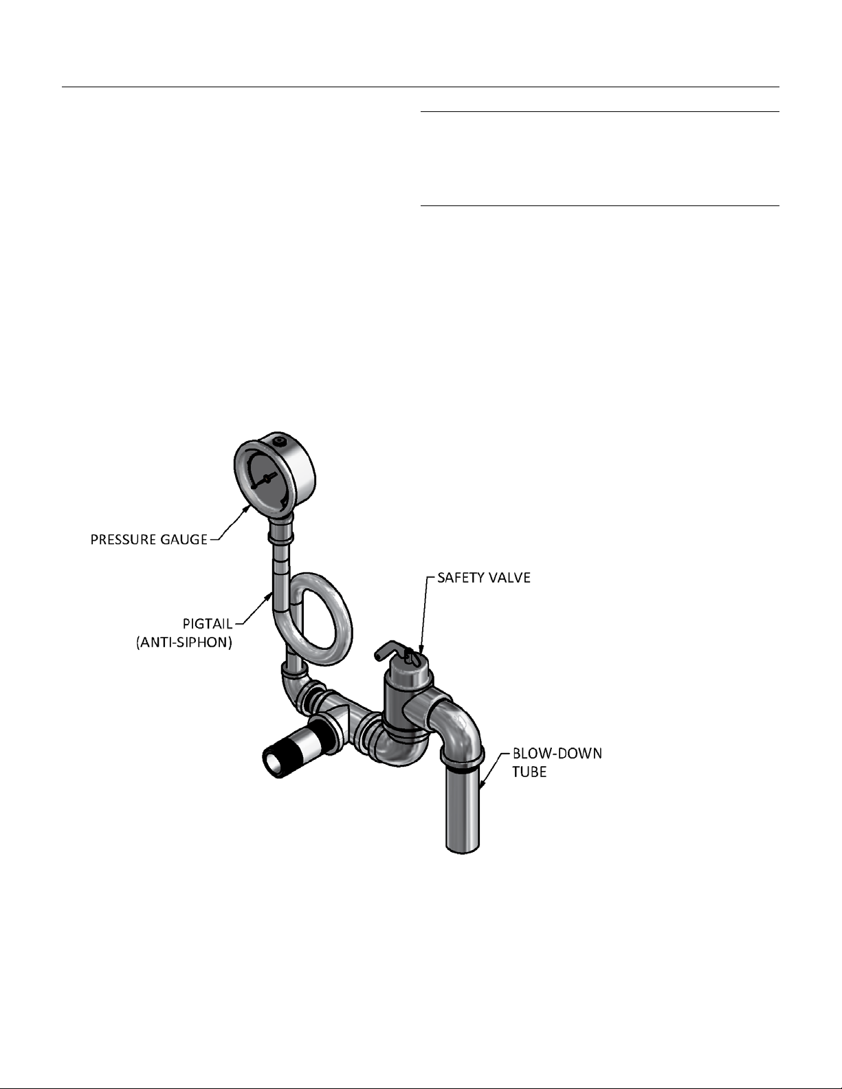
ILLUSTRATIONS
Safety Relief Valve, Pressure Gauge, Pigtail
7

Caring For Stainless Steel
This section provides specic guidelines for cleaning and protecting the stainless steel surface of your
equipment.
Important!
Always disconnect power before cleaning (or servicing) the unit. Never spray the control console, electrical
controls, gas controls, or connections with water. Clean these areas by wiping them with a clean, damp cloth.
The stainless steel can be cared for using any good commercial stainless steel cleaner or polish. Contrary to
popular belief, stainless steel remains resistant to corrosion only as long as its passive surface remains intact.
There are some basic rules to prevent the breakdown of this surface.
Only plastic scouring pads and soft cloths should be used, since they will not damage the stainless steel surface.
Never use anything that will scratch the surface such as steel pads, wire brushes, or scrapers. In the pan, scratches
make cleaning more dicult and provide places for bacteria to collect and grow. Never use steel wool since it
can leave particles embedded in the pan and can also lead to eventual corrosion and pitting. Never let deposits
from water, particularly hard water, or deposits from food sit on the surface for extended periods. Wipe up
deposits and spills promptly. After cleaning, rinse o the cleaning agents thoroughly with water, wipe dry, and
then allow the surface to air dry. Oxygen actually helps maintain stainless steel’s protective surface.
Never use cleaners containing chlorides (or quaternary salts, since they
can also contribute to pitting and rusting). Use only alkaline, alkaline-
chlorinated, or non-chloride cleaners.
Tip: If you’ve been doing a lot of continued boiling or steaming, you
may notice a build-up of lime or scale in the pan. This cleans up easily
using vinegar, a vinegar/water mixture, or any commercial de-liming / de-
scaling solution.
Sanitizing
Suggested Tools:
a. Cleaner, such as Klenzade HC-10 or HC-32 from ECOLAB, Inc.
b. Kettle brushes in good condition
c. Sanitizer such as Klenzade XY-12.
d. Film remover such as Klenzade LC-30.
Procedure:
1. Clean food contact surfaces as soon as possible after use. If the unit is in continuous use, thoroughly clean
and sanitize the interior and exterior at least once every 12 hours.
2. Scrape and ush out food residues. Be careful not to scratch the unit with metal implements.
3. Prepare a hot solution of the detergent/cleaning compound as instructed by the supplier. Clean the unit
thoroughly. A cloth moistened with cleaning solution can be used to clean controls, housings, and electrical
conduits.
4. Rinse the unit thoroughly with hot water, and then drain completely.
5. As part of the daily cleaning program, clean soiled external and internal surfaces. Remember to check the
sides of the unit and control housing.
8

Caring For Stainless Steel
6. To remove stuck materials, use a brush, sponge, cloth, plastic or rubber scraper, or plastic wool with the
cleaning solution. To reduce eort required in washing, let the detergent solution sit in the unit and soak into
the residue. Do NOT use abrasive materials or metal tools that might scratch the surface. Scratches make the
surface harder to clean and provide places for bacteria to grow.
7. The outside of the unit may be polished with a stainless steel cleaner such as“Zepper”from Zep Manufacturing
Co.
8. When equipment needs to be sanitized, use a solution equivalent to one that supplies 200 parts per million
available chlorine. Obtain advise on sanitizing agents from your supplier of sanitizing products. Following
the supplier’s instructions, apply the agent after the unit has been cleaned and drained. Rinse o the sanitizer
thoroughly.
9. It is recommended that each piece of equipment be sanitized just before use.
10. If there is diculty removing mineral deposits or a lm left behind by hard water or food residues, clean the
unit thoroughly and use a deliming agent, like Lime-Away® from Ecolab, in accordance with the manufacturer’s
directions. Rinse and drain the unit before further use.
NOTICE: NEVER LEAVE A CHLORINE SANITIZER IN CONTACT WITH STAINLESS STEEL SURFACES LONGER THAN 30
MINUTES. LONGER CONTACT CAN CAUSE STAINING AND CORROSION.
9

Parts List
Part Number Description Qty
407998 Primary thermostat 1
407998-D-1 Dial, primary thermostat 1
407793 Grommet, thermostat shaft 1
407451 Indicator light red 240v 1
407452 Indicator light amber 240v 1
430085 Tilt switch 20 amp, 240 volt 1
440280 Siphon (pigtail) ¼” npt 1
456725 Safety valve 50 psi / 625 lbs/hr 1
456727 Pressure gauge 30Hg-0-60 1
405296 Two-gang weatherproof junction box 1
405296C Cover two-gang weatherproof junction box 1
406555 Terminal block 985GP03 1
408015-15 Contactor 15 amp 600V 2
408015-25 Contactor 25 amp 600V 2
408015-40 Contactor 40 amp 600V 2
408015-60 Contactor 60 amp 600V 2
430033 Transformer all volts, 480,440,415,380 1
400749-1 Ground lug 14 to 6 2
406619 Fuse 2 amp 2
400780-2 Fuse block 2 pole 1
406578 Terminal block jumped 2
407615 Rocker switch 1
408580 Indicator light green 240V 1
455950 Heater cartridge 4kW 440 volt - SEOT2 3
455634 Heater cartridge 2kW 240 volt - SEOT2)3
455635 Heater cartridge 2kW 480 volt - SEOT2 3
455636 Heater cartridge 4kW 240 volt - SEOT2 3
455637 Heater cartridge 4kW 480 volt - SEOT2 3
455427 Low water relay 1500A 240V 1
450589 Insulating spacers As required
407415 Basket insert TEH-40/10F As required
407472 Basket insert TEH-20/5f As required
10
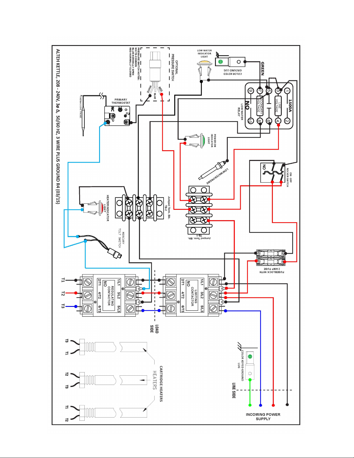
Wiring Diagrams
ALTEH 5 & 10 GAL. 208-240/3PH
11

Wiring Diagrams
ALTEH-5 & 10 GAL. 440,460 & 480/3PH
12

Wiring Diagrams
ALTEH-5 & 10 GAL. 380, 415V/3PH
13

Maintenance & Service Log
Model No.: Purchased From:
Serial No.: Date Purchased:
Purchase Order No.: Location Installed:
Date Installed:
Date Maintenance Performed: Performed By:
14

31
LIMITED WARRANTY
One Year Parts and LaborOne Year Parts and Labor
AccuTemp Products, Inc. ( AccuTemp ) warrants that your AccuTemp equipment will be free of defects in
material and workmanship under normal use for a period of twelve (12) months from installation or fifteen
(15) months from date of shipment from AccuTemp, whichever date first occurs (the Warranty Period ).
Registration of AccuTemp equipment is required at time of installation.
Damage to AccuTemp equipment that occurs during shipment must be reported to the carrier, and is not
covered under this warranty. The reporting of any damage during shipment is the sole responsibility of the
commercial purchaser/user of such AccuTemp equipment.
AccuTemp provides an active service department, which should be contacted and advised of service issues
regardless of warranty period.
During the warranty period, AccuTemp agrees to repair or replace, at its option, F.O.B. factory, any part
which proves to be defective due to defects in material or workmanship, provided the equipment has not
been altered in any way and has been properly installed, maintained, and operated in accordance with the
instructions in the AccuTemp Owners Manual.
During the warranty period, AccuTemp also agrees to pay for any factory authorized equipment service
agency (within the continental United States and Canada) for reasonable labor required to repair or
replace, at our option, F.O.B. factory, any part which proves to be defective due to defects in materials
or workmanship, provided the service agency has received advance approval from AccuTemp factory
service to perform the repair or replacement. This warranty includes travel time not to exceed two hours
and mileage not to exceed 50 miles (100 miles round trip), but does not include post start-up assistance
or training, tightening of loose fittings or external electrical connections, minor adjustments, gaskets,
maintenance, or cleaning. AccuTemp will not reimburse the expense of labor required to replace parts after
the expiration of the warranty period.
Proper installation is the responsibility of the dealer, owner-user, or installing contractor and is not covered
by this warranty. While AccuTemp products are built to comply with applicable standards for manufacturers,
including Underwriters Laboratories (UL) and National Sanitation Foundation (NSF), it is the responsibility of
the owner and the installer to comply with any applicable local codes that may exist.
AccuTemp makes no other warranties or guarantees, whether expressed or implied, including any
warranties of performance, merchantability, or fitness for any particular purpose. AccuTemp s liability on any
claim of any kind, including negligence, with respect to the goods and services covered hereunder, shall
in no case exceed the price of the goods and services, or parts thereof, which gives rise to the claim. In no
event shall AccuTemp be liable for special, incidental, or consequential damages, or damages in the nature
of penalties.
This constitutes the entire warranty, which supersedes and excludes all other warranties, whether written,
oral, or implied.
Product Warranty
IMPORTANT
Improper installation can aect your warranty. Installation is the responsibility of the Dealer,
Owner/User or the Installation Contractor. See: Section One, Installation of the Owner s Manual.
U.S. & Canada Sales Only

IMPORTANT SERVICE INFORMATION
AccuTemp Product, Inc. Technical & Customer Support Technician is
available Monday thru Sunday, 7:00am to 7:00pm EST.
This manual suits for next models
1
Table of contents
Other AccuTemp Commercial Food Equipment manuals


Popular Commercial Food Equipment manuals by other brands

Mobile Sink Company
Mobile Sink Company Odyssey Troubleshooting and caring

Chocolate World
Chocolate World M1291 Use and maintenance manual

ARTEZEN
ARTEZEN CALYBRA HD L manual

TURBRO
TURBRO Fireside RB01 user manual

Equipex
Equipex SODIR RBE-8 Operation manual

KitchenAid
KitchenAid KUBL214KSB Use and care guide


