Comtrol Rocket Port C52 User manual

1
User Manual
Rocket Port Converter C52/C53
2000137 Rev B

Overview 2
Overview
The Comtrol Rocket Port Converters are smart RS-232 to RS-422/485 bi-directional converters. They allow you to convert one RS-232
port to and from either RS-422 or RS-485 ports. You use the converter to control devices with a longer than normal distance between the
host and the device, and to communicate with several devices. Operations like point-to-point and multi-drop are available to meet your
needs.
Rocket Port Converter C53
Features:
•Both the C52 and C53 are RS-232 to RS-422/RS-485 bidirectional converters. The C53 includes isolation protection against high
voltage up to 2000V.
•Comtrol locates the switch settings inside the converter. This protects the system from unintentional changes that would introduce
communication errors without any warning. To make any changes to the operation mode, simply remove the two screws to open the
cover.
•You can power the C52/C53 either from a DC +9V to +30V, 150A power adapter, or the pin 6 and pin 7 on the terminal block.
•LED indicators show the status of transmitting and receiving data, RTS signal, and power.
•Comtrol has added a protect resistor inside the unit to avoid over-current from the remote ground to the converter’s ground.
•Mounting Kit lets you mount the C52/C53 on a wall or any surface.

Specifications 3
Specifications
C52/C53 Specification
Current consumption: C52 - DC +9V to +30V, 150mA max.
C53 - DC +9V to +30V, 270mA max.
Baud rate: Up to 921.6K bps under 500 feet
(0.15Km)
Distance Up to 4000 feet (1.2 Km) under
115200 bps
Note: Baud rate is dependent upon hardware and operating system
configuration.
Optical isolation
C52
C53
No
2000V DC for all signals
Surge protection 25KV ESD for all signals
Dimension 90mm x 60mm x 21mm
Environmental Condition Value
Operating Temperature 0 to 55oC
Electromagnetic Compliance Status
Emissions:
RFI Emissions: Class A
EN 55022
FCC Part 15: Class A Yes
Immunity:
EN 50082-1 Yes

Installation 4
Package Check List
C52 (C53) RS-232 to RS-422/RS-485 bidirectional converter
Power adapter
Cable
Mounting kit
User manual
Installation
1. The RS-232 and RS-422-485 ports are labeled clearly on the surface of the C52 and C53 converters. Prepare the RS-232 cable and
decide the operation mode as well as the 2/4-wire cable in advance. See the RS-232 Cable Wiring and Operations sections.
If you need to change the operation mode, remove the two screws on top of the converter and open the cover. Change the switches to
reflect your desired mode.
The DIP switches set the operation mode (RS-422 or RS-485) and the control mode (by RTS or ADDC) for RS-485 mode.
Switch settings tables of Switch 1 and Switch 2 are as follows:
2. When you are using the RS-485 in a multi-drop mode, Comtrol includes one jumper per unit to enable the termination resistor. You
only enable the jumper (JP1) at the extreme ends of the chain.
In the RS-422 mode, the RxD always enables a 120 Ohm terminating resistor.
LED Indicators
There are LED indicators for TxD, RxD, RTS, and PWR on top of the unit. The indicators are not on when the unit is not connected with
a signal or power.
•The TxD indicator stands for transmitted data from RS-232 to RS-422 or RS-485. It illuminates when connected and data is
transmitting.
•The RxD indicator stands for received data from RS-422 or RS-485 to RS-232. It illuminates when connected and receiving data.
•The RTS indicator is for the RS-232 RTS signal (Request To Send). It illuminates when it is connected and the RTS signal is on.
•The PWR indicator illuminates when the power is on and not lit when the power is off or not connected.
Switch 1
RS-422 mode Off
RS-485 mode On
Switch 2
By RTS Off
Auto Data Direction Control (ADDC) On
AUTO
485
RTS
422
JP1

RS-422/RS-485 Pinouts 5
RS-422/RS-485 Pinouts
The RS-422/RS485 interface with the RJ45 Jack connector or Terminal Block Connector is shown as follows:
Note: Pin 6 and Pin 7 of the Terminal Block are for Power GND and Power Input, which is an alternate option for the power adapter. Be
careful that you DO NOT confuse the RS-422/RS-485 (Signal) GND with the power GND.
C52/C53 RS-422
RJ45 Jack Terminal Block
Connector
Pinouts Signals Connector
Pinouts Signals
1TxD-(A) 1TxD+(B)
2RTS-(A) 2TxD-(A)
3RTS+(A) 3RxD+(B)
4Signal GND 4RxD-(A)
5TxD+(B) 5Signal GND
6RxD+(B) 6Power GND
7Signal GND 7VCCA(9v)
8CTS+(B)
9CTS-(A)
10 RxD-(A)
C52/C53 RS-485
RJ45 Jack Terminal Block
1Data-(A) 1Data+(B)
2nc 2Data-(A)
3nc 3nc
4Signal GND 4nc
5Data+(B) 5Signal GND
6nc 6Power GND
7Signal GND 7VCCA(9V)
1 2 3 4 5 6 7
RJ-45 Connector Terminal Block Connector
1 2 3 4 5 6 7 8 9 10

Operation 6
Operation
The C52/C53 supports four kinds of operations. They are:
•Point-to-point, 4-wire full duplex
•Point-to-point, 2-wire half duplex
•Multidrop, 4-wire full duplex
•Multidrop, 2-wire half duplex
Note: If possible, connect the GND of both sides together to gain better signals. For example, you may need one more GND connection in
addition to the 4-wire or 2-wire connections.
Note: For C53, connect the GND at the terminal block to the earth ground to provide a ground path to prevent electric shock caused by
lightning, no matter whether you use the RJ45 or terminal block RS-422/RS-485.
Basic Communication Wiring
Before placing a converter in an existing network, you should configure it. The following diagrams show a typical layout for both
converters.
Power
Power GND
RS-422/485
RS-422/485RS-232
PC
Power
TxD(2)
RxD(3)
RTS(4)
CTS(5)
DSR(6)
GND(7)
DCD(8)
DTR(20)
RxD(2) TxD+(B))
TxD(3) TxD-(A)
CTS(4) RxD+(B)
RTS(5) RxD-(A)
DTR(6) GND
GND(7)
DCD(8)
DSR(20)
RxD+(B)
TxD+(B)
TxD-(A)
GND
RxD-(A)
RS-232
HostD25 Female
Connector
BA52/53 Converter
RS-422 Devices
TxD(2)
RxD(3)
RTS(4)
CTS(5)
DSR(6)
GND(7)
DCD(8)
DTR(20)
RxD(2) Data+(B))
TxD(3) Data-(A)
CTS(4) GND
RTS(5)
DTR(6)
GND(7)
DCD(8)
DSR(20)
Data+(B)
Data
GND-(A)
RS-232 RS-485
HostD25 Female
Connector
B
A52/53 Converter
RS-485 Devices

Reference Section 7
Reference Section
RS-232 Pinouts
The following depicts the RS-232 interface with the RJ45 connector.
Note: The DTR and DSR pins have been shorted. This releases the users from
the hardware flow control wiring problems. Therefore, only two types of
RS-232 cable wiring examples are listed in the following.
C52/C53 RJ45
Connector Pinouts RS-232 Signals
1DCD Always On
2DTR
3CTS
4GND
5RxD
6TxD
7GND
8RTS
9DSR
10 ------

RS-232 Cable Wiring 8
RS-232 Cable Wiring
Type 1: To connect the RS-232 side of a C52 or C53 to a DTE (Data Terminal Equipment or “your PC”) or DCE (Data Communications
Equipment or “remote device”). Check the precise DTE/DCE pinouts. For an example, see the following DTE/DCE pinout
examples.
C52/C53 to DTE Cable
Signal Pin Pin Signal
DCD 1 8 DCD
DTR 2 20 DSR
CTS 3 5 RTS
RxD 5 3 TxD
TxD 6 2 RxD
GND 7 7 GND
RTS 8 4 CTS
DSR 9 6 DTR
RJ45 DB-25
Male
C52/C53 to DTE Cable
Signal Pin Pin Signal
DCD 1 1 DCD
DTR 2 4 DSR
CTS 3 8 RTS
RxD 5 2 TxD
TxD 6 3 RxD
GND 7 5 GND
RTS 8 7 CTS
DSR 9 6 DTR
DB-9
Male
RJ45
C52/C53 to DCE Cable
Signal Pin Pin Signal
DCD 1 8 DCD
DTR 2 6 DSR
CTS 3 4 RTS
RxD 5 2 TxD
TxD 6 3 FxD
GND 7 7 GND
RTS 8 5 CTS
DSR 9 20 DTR
RJ45 DB-25
Female

RS-232 Cable Wiring 9
Type 2: To connect the RS-232 side of a C52 or C53 to a DTE (Data Terminal Equipment or “your PC”) with a 3-pin wiring if you don’t
require hardware flow control.
C52/C53 to DTE Cable
Signal Pin Pin Signal
TxD 5 3 RxD
RxD 6 2 TxD
GND 7 7 GND
RTS 8 5 CTS
CTS 3 4 RTS
DSR 9 20 DTR
DTR 2 6 DSR
DCD 1 8 DCD
RJ45 DB-25
Male
C52/C53 to DTE Cable
Signal Pin Pin Signal
TxD 6 2 RxD
RxD 5 3 TxD
GND 7 5 GND
RTS 8 8 CTS
CTS 3 7 RTS
DSR 9 4 DTR
DTR 2 6 DSR
DCD 1 1 DCD
DB-9
Male
RJ45
C52/C53 to DCE Cable
Signal Pin Pin Signal
TxD 6 2 RxD
RxD 5 3 TxD
GND 7 7 GND
RTS 8 4 CTS
CTS 3 5 RTS
DSR 9 6 DTR
DTR 2 20 DSR
DCD 1 8 DCD
RJ45 DB-25
Female

Impedance Matching and Termination Resistors 10
Impedance Matching and Termination Resistors
When an electrical signal travels through two different resistance junctions in a transmission line, the mismatch will sometimes cause
signal reflection. Signal reflection causes signal distortion, which in turn will contribute to communication errors. The solution to this
problem is to establish the same impedance at the RS-485 line ends as in the line itself by terminating them with resistors.
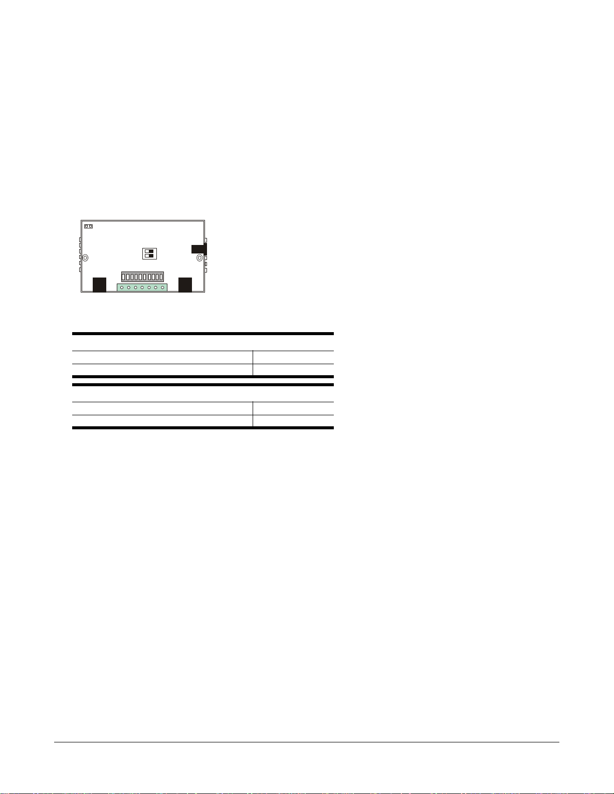
Comtrol manufactures the converter with jumpers to enable and disable termination resistors. To set the jumper, remove the two screws
in the cover and set the jumper to cover both pins.
Troubleshooting
If installation fails or you are trying to resolve a problem, you should try the following before calling the Comtrol technical support line:
For data transmission failure:
•Check that you are using the correct power adapter.
•Check that switches 1 and 2 are properly set.
For data loss or error:
Check that the data rate and data format are the same for both devices
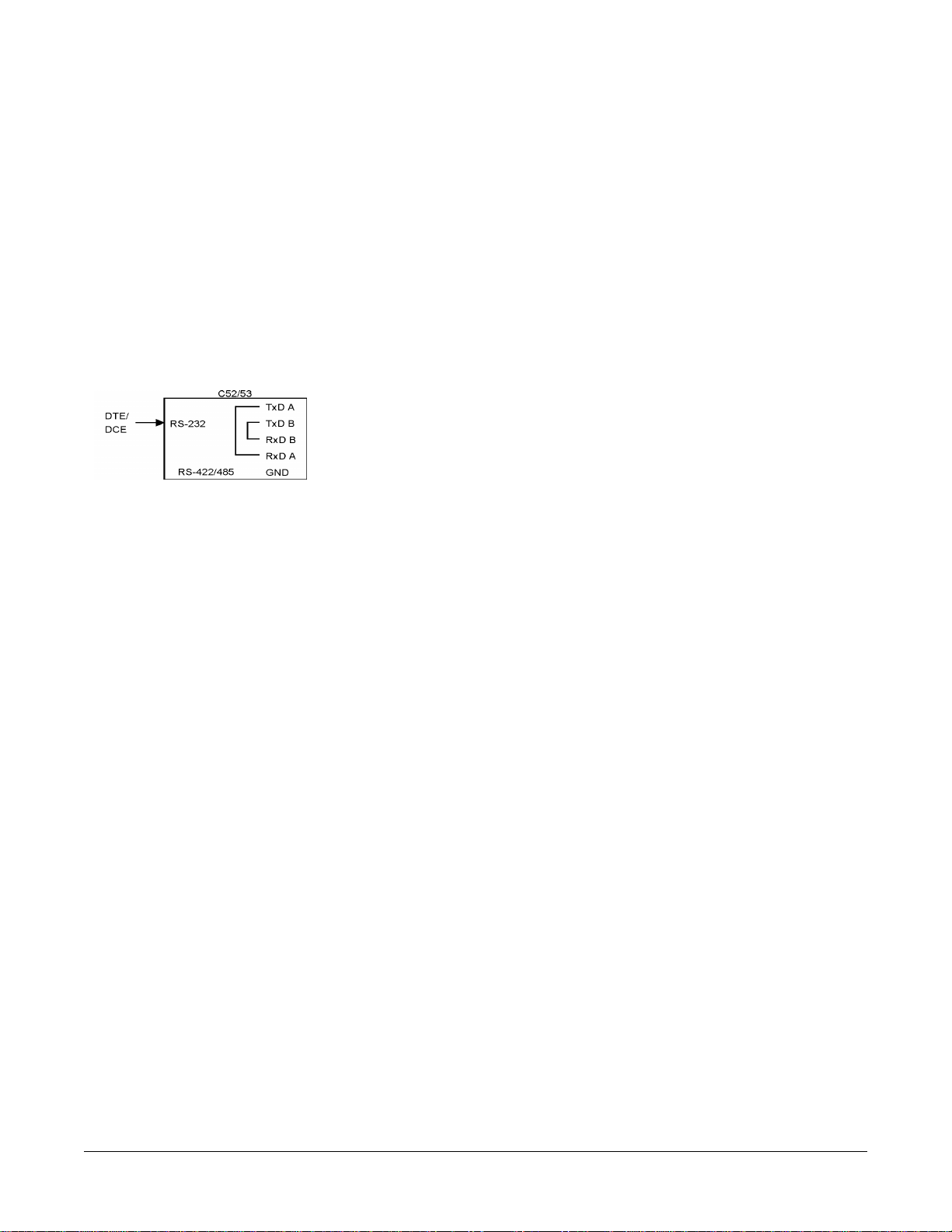
Self Test
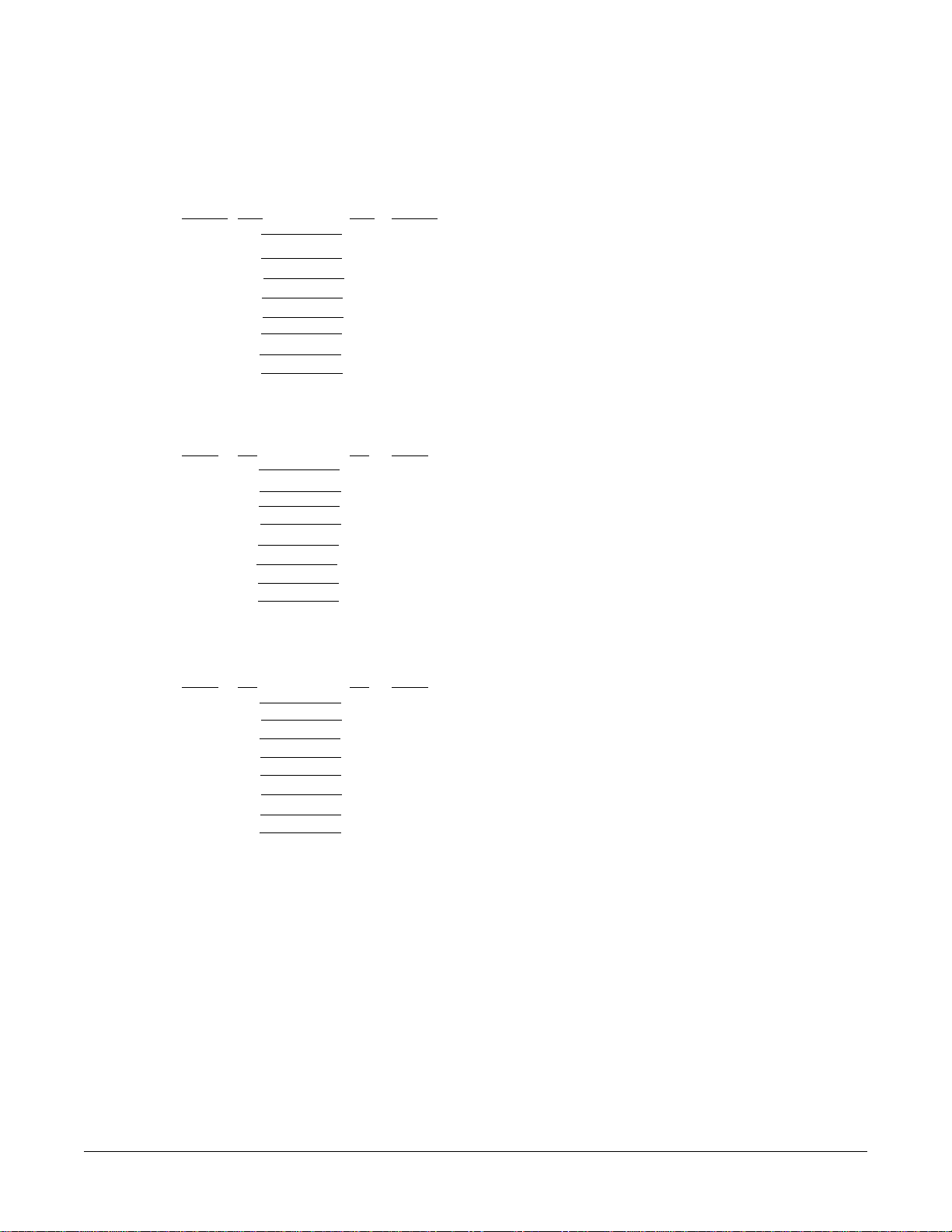
This configuration is for C52/C53 self test. Run the terminal emulation program to see if what you received is what you typed.
In the graph, TxD A, TxD B, RxD A, and RxD B could be either from RJ45 or the terminal block.
FCC Notices
Radio Frequency Interference (RFI) (FCC 15.105)
This equipment has been tested and found to comply with the limits for Class A digital devices pursuant to Part 15 of the FCC Rules.
This equipment generates, uses, and can radiate radio frequency energy, and if not installed and used in accordance with the instruction
manual, may cause harmful interference to radio communications. However, there is no guarantee that interference will not occur in a
particular installation. If this equipment does cause harmful interference to radio or television reception, which can be determined by
turning the equipment off and on, the user is encouraged to try and correct the interference by one or more of the following measures:
•Reorient or relocate the receiving antenna.
•Increase the separation between the equipment and the receiver.
•Connect the equipment to an outlet on a circuit different from that to which the receiver is connected.
•Consult the dealer or an experienced radio/TV technician for help.
Labeling Requirements (FCC 15.19)
This equipment complies with Part 15 of FCC Rules. Operation is subject to the following two conditions:
•This device may not cause harmful interference, and
•This device must accept any interference received, including interference that may cause undesired operation.
Modifications (FCC 15.21)
Changes or modifications to this equipment not expressly approved by Comtrol Corporation may void the user’s authority to operate this
equipment.
Serial Cables (FCC 15.27)
This equipment is certified for Class A operation when used with shielded cables.

Contacting Technical Support 11
Contacting Technical Support
Comtrol has a staff of support technicians available to help you. Before you call, please have the following information available:
Comtrol product model number: _______________________
Serial number: _______________________________________
Operating system type and release: _____________________
Computer make: _____________________________________
Computer model: _____________________________________
Processor speed: ______________________________________
Comtrol Corporate Headquarters:
•Web site: http://www.comtrol.com
•E-mail: [email protected]
•FAX: (763) 494-4199
•Tel: (763) 494-4100
•FTP site: ftp://ftp.comtrol.com
Comtrol UK Technical Support
•Web site: http://www.comtrol.co.uk
•E-mail: [email protected]
•FAX: +44 (0) 1 869-323-211
•Tel: +44 (0) 1 869-323-220
Copyrights and Trademarks
Copyright (c)2000 Comtrol Corporation. All Rights Reserved.
Comtrol Corporation makes no representations or warranties with regard to the contents of this document or to the suitability of the
Comtrol products for any particular purpose. Specifications subject to change without notice. Some features may not be available at the
time of publication. Contact your reseller for current product information.
RocketPort is a registered trademark of Comtrol Corporation.
Other product and company names mentioned herein may be the trademarks and/or registered trademarks of their respective owners.

Copyrights and Trademarks 12
Notes:
This manual suits for next models
1
Table of contents
Popular Media Converter manuals by other brands

AVT
AVT MAGIC AE4 quick guide

Ambery
Ambery 4-Way Operation manual

Viessmann
Viessmann 5280 Operation manual

Datalogic
Datalogic Profibus AMT58 13x12 PB Series instruction manual

DEVA Broadcast
DEVA Broadcast DB9000-TX Maintenance and operation instruction manual

Vertiv
Vertiv NetSure IPE Series Installation and user manual