EDT VisionLink F Series User manual

User’s Guide
VisionLink F-Series
Camera Link Frame Grabbers
for PCI Express
Date: 2019 April 29
Rev.: 0012

EDT, Inc.
2
EDT | Engineering Design Team, Inc.
3423 NE John Olsen Ave
Hillsboro, OR 97124 U.S.A.
Tel: +1-503-690-1234 | Toll free (in U.S.A.): 800-435-4320
Fax: +1-503-690-1243
www.edt.com
EDTTMand Engineering Design TeamTMare trademarks ofEngineering Design Team, Inc.All other trademarks, service marks,
and copyrights are the property of their respective owners†.
© 1997-2019 Engineering Design Team, Inc. All rights reserved.
FCC Compliance: EDT devices described herein are in compliance with part 15 of the FCC Rules. Operation is subject to two
conditions: (1) The device may not cause harmful interference, and (2) the device must accept any interference received,
including interference that may cause undesired operation.
Thisequipmenthasbeentestedandfoundtocomplywith thelimitsforaClassA digitaldevice,pursuant topart 15 ofFCC Rules.
These limits are designed to provide reasonable protection against harmful interference in a commercial environment. This
equipment generates, uses, and can radiate radio frequency energy and, if not installed and used as described in the user’s
guide, may cause harmful interference to radio communications. Operating this equipment in a residential area is likely to cause
harmful interference, in which case the user will be required to correct the interference at his or her own expense.
Caution: Changes or modifications not expressly approved by Engineering Design Team, Inc. could void your warranty to
operate this equipment.

EDT, Inc.
3
Terms of Use Agreement
Definitions. This agreement, between Engineering Design Team, Inc. (“Seller”) and the user or distributor (“Buyer”), covers the
use and distribution of the following items provided by Seller: a) the binary and all provided source code for any and all device
drivers,softwarelibraries,utilities, andexampleapplications(collectively, “Software”); b)thebinary andallprovidedsource code
foranyandallconfigurableorprogrammabledevices(collectively,“Firmware”); andc)thecomputerboardsandallotherphysical
components (collectively, “Hardware”). Software, Firmware, and Hardware are collectively referred to as “Products.” This
agreementalsocoversSeller’s publishedLimitedWarranty(“Warranty”) andallotherpublishedmanualsandproductinformation
in physical, electronic, or any other form (“Documentation”).
License. Seller grants Buyer the right to use or distribute Seller’s Software and Firmware Products solely to enable Seller’s
HardwareProducts.Seller’s SoftwareandFirmwaremustbeused onthesamecomputerasSeller’s Hardware.Seller’s Products
and Documentation are furnished under, and may be used only in accordance with, the terms of this agreement. By using or
distributing Seller’s Products and Documentation, Buyer agrees to the terms of this agreement, as well as any additional
agreements (such as a nondisclosure agreement) between Buyer and Seller.
Export Restrictions. Buyer will not permit Seller’s Software, Firmware, or Hardware to be sent to, or used in, any other country
except in compliance with applicable U.S. laws and regulations.
For clarification on such laws and regulations, see the website for...
•
U.S. Department of Commerce, Bureau of Industry and Security
https://www.commerce.gov/bureau-industry-and-security
...or, if ITAR status is indicated in the product’s documentation (on the title page or near the beginning), see the website for...
•
U.S. Department of State, Bureau of Political-Military (PM) Affairs, Directorate of Defense Trade Controls (DDTC)
https://www.pmddtc.state.gov/regulations_laws/itar.html
Limitation of Rights. Seller grants Buyer a royalty-free right to modify, reproduce, and distribute executable files using the
Seller’s Software and Firmware, provided that: a) the source code and executable files will be used only with Seller’s Hardware;
b)
Buyeragreestoindemnify,holdharmless,anddefendSellerfromandagainstanyclaimsorlawsuits,includingattorneys’ fees,
that arise or result from the use or distribution of Buyer’s products containing Seller’s Products. Seller’s Hardware may not be
copied or recreated in any form or by any means without Seller’s express written consent.
No Liability for Consequential Damages. In no event will Seller, its directors, officers, employees, oragents be liable to Buyer
for any consequential, incidental, or indirect damages (including damages for business interruptions, loss of business profits or
information, and the like) arising out of the use or inability to use the Products, even if Seller has been advised of the possibility
of such damages. Because some jurisdictions do not allow the exclusion or limitation of liability for consequential or incidental
damages, the above limitations may not apply to Buyer. Seller’s liability to Buyer for actual damages for any cause whatsoever,
and regardless of the form of the action (whether in contract, product liability, tort including negligence, or otherwise) will be
limited to fifty U.S. dollars($50.00).
Limited Hardware Warranty. Seller warrants that the Hardware it manufactures and sells shall be free of defects in materials
and workmanship for a period of 12 months from date of shipment to initial Buyer. This warranty does not apply to any product
that is misused, abused, repaired, or otherwise modified by Buyer or others. Seller’s sole obligation for breach of this warranty
shall be to repair or replace (F.O.B. Seller’s plant, Beaverton, Oregon, USA) any goods that are found to be non-conforming or
defective as specified by Buyer within 30 days of discovery of any defect. Buyer shall bear all installation and transportation
expenses, and all other incidental expenses and damages.
Limitation of Liability. In no event shall Seller be liable for any type of special consequential, incidental, or penal damages,
whether such damages arise from, or are a result of, breach of contract, warranty, tort (including negligence), strict liability, or
otherwise. All references to damages herein shall include, but notbe limited to: loss of profit or revenue; loss of use ofthe goods
or associated equipment; costs of substitute goods, equipment, or facilities; downtime costs; or claims for damages. Seller shall
not be liable for any loss, claim, expense, or damage caused by, contributed to, or arising out of the acts or omissions of Buyer,
whether negligent orotherwise.
No Other Warranties. Seller makes no other warranties, express or implied, including without limitation the implied warranties
of merchantability and fitness for a particular purpose, regarding Seller’s Products or Documentation. Seller does not warrant,
guarantee, or make any representations regarding the use or the results of the use of the Products or Documentation or their
correctness, accuracy, reliability, currentness, or otherwise. All risk related to the results and performance of the Products and
Documentation is assumed by Buyer. The exclusion of implied warranties is not permitted by some jurisdictions. The above
exclusion may not apply to Buyer.
Disclaimer.Seller’s ProductsandDocumentation,includingthisdocument,aresubjecttochangewithoutnotice.Documentation
does not represent a commitment fromSeller.

EDT, Inc.
4
Contents
Overview.....................................................................................................................................................................6
Included Files.......................................................................................................................................................6
Power Over Camera Link (PoCL) ........................................................................................................................7
Related Resources...............................................................................................................................................7
Requirements .............................................................................................................................................................8
Installation...................................................................................................................................................................8
Setting the Camera Model..........................................................................................................................................9
Image Capture and Display GUI.................................................................................................................................9
Units, Connectors, and Channels.............................................................................................................................11
LEDs.........................................................................................................................................................................12
Serial Communication...............................................................................................................................................12
At Initialization....................................................................................................................................................12
From Command Line .........................................................................................................................................12
From EDT GUI ...................................................................................................................................................12
From Your Application........................................................................................................................................13
From Camera Manufacturer’s Application .........................................................................................................13
Example and Utility Applications ..............................................................................................................................13
Triggering..................................................................................................................................................................16
No Triggering –Freerun (Continuous)...............................................................................................................16
Triggered by EDT Board (On-Demand).............................................................................................................17
Triggered by EDT Board (Fixed Period).............................................................................................................17
Pulse-Width Triggered (Controlled or Level)......................................................................................................18
External Trigger Direct to Camera .....................................................................................................................18
External Trigger Passthrough ............................................................................................................................18
External Triggering Pins.....................................................................................................................................19
Simulation and Testing.............................................................................................................................................20
Programming............................................................................................................................................................21
Building or Rebuilding an Application ................................................................................................................21
Compiling vlviewer .............................................................................................................................................22
Firmware: FPGA Configuration (.bit) Files................................................................................................................22
Checking and Loading the Firmware .................................................................................................................23
Corrupted Firmware...........................................................................................................................................24
Troubleshooting........................................................................................................................................................24
Board Not Seen..................................................................................................................................................25
Problems With Software Installation ..................................................................................................................25
Corrupted Images, Slow Acquisition, Timeouts, Data Loss...............................................................................26
Problems With Bandwidth..................................................................................................................................27
Problems Acquiring Images With EDT Applications..........................................................................................27
Problems With Your Applications.......................................................................................................................28
Problems With Threads......................................................................................................................................28
Problems With Firmware....................................................................................................................................28
Appendix A: Pin Assignments...................................................................................................................................29
Appendix B: Diagrams –Boards and Cabling ..........................................................................................................30
VisionLink F-Series Frame Grabbers.................................................................................................................30
F1 and F4.....................................................................................................................................................................30
Additional External Inputs ..................................................................................................................................31
Via Berg or Optional Lemo Connector.........................................................................................................................31
Via Optional Cable Assembly.......................................................................................................................................31
Via Ribbon Cabling and D9 Connectors.......................................................................................................................32
Appendix C: Timestamping.......................................................................................................................................33
Camera Configuration File Directives ................................................................................................................33

EDT, Inc.
5
Footer Format ....................................................................................................................................................33
IRIG API.............................................................................................................................................................35
Revision Log.............................................................................................................................................................37

VisionLink F-series
Overview
EDT, Inc.
2019 April 29
6
VisionLink F-series
Overview
This guidecovers EDTVisionLink F-series frame grabbers, which providefast, high-resolutionimage capture andDMA
between an external Camera Link camera and a host computer.
These frame grabbers are designed for PCIe Gen2 but can work with other PCIe generations; however, performance
is limited by the generation of the board or slot, whichever is lower.
Companion products include remotecamera extenders (RCX) overfiber; for details,see RelatedResources onpage 7.
Available configurations for the F-series are shown in Table 1.
Table 1. VisionLink F-series frame grabbers for Camera Link
Product
Bus spec
Camera Link
Part
Product
name
x lanes
modes
number
description
VisionLink F1
PCIe x1
Base
019-14853
Half-height backpanel, 1 SDR
019-14854
Half-height backpanel, 2 SDRs, 128 MB DDR3, IRIG-B
019-14836
Full-height backpanel, 1 SDR
019-14852
Full-height backpanel, 2 SDRs, 128 MB DDR3, IRIG-B, Lemo
VisionLink F4
PCIe x4
Base–
TBD
Half-height backpanel
full
019-14856
Full-height backpanel
019-14857
Full-height backpanel, Lemo
Included Files
For the above products, your EDT installation package includes README files for quick start information and special
cases (README.*), as well as device drivers for supported operating systems and source code and binaries for...
•
GUI capture and display applications (vlviewer, pdvshow)
•
Standalone initialization applications (initcam, camconfig)
•
Command-line capture and display applications (take, simple_take, simplest_take, simple_*)
•
Command-line serial communication tool(serial_cmd)
•
Diagnostic tools (pciload, pciediag, dvinfo, pdb)
•
API libraries (libpdv, libedt, and associated source files)
•
Makefiles for Windows and Linux(makefile)
•
Visual Studio project and solution files (*/*.vcproj, */*.sln)
•
Camera configuration files(camera_config/*.cfg)
•
Board firmware files (flash/* directories)
•
Windows silent install / uninstall example batch files (wdf/install/*.bat)

VisionLink F-series
Overview
EDT, Inc.
2019 April 29
7
For detailed descriptions of selected programs, see Example and Utility Applications on page 13. For a more complete
list of files and quick-start information, consult README.pdv in your EDT installation package (see Installation on
page 8). For programming information, consult the EDT API (see Related Resources on page 7).
Power Over Camera Link (PoCL)
VisionLinkframegrabberssupportPoweroverCameraLink(PoCL)viatheMSP430usingsafepower.PoCLisenabled
via software (implementation TBD). For PoCL pin assignments, see Appendix A: Pin Assignments on page 29.
Related Resources
To find product-specific information that is related to a particular EDT product, go to .edt.com and open the relevant
product page. There you’ll see links to that product’s datasheet (specifications), user’s guide, and other resources.
In addition, the resources below may be helpful or necessary for your applications.
EDT Resources
•
Application programming interface (API) edt.com/dv_api
•
Installation packages (Windows, Linux) edt.com/download-hub
•
VisionLink F1 datasheet / specifications edt.com/product/visionlink-f1
•
VisionLink F4 datasheet / specifications edt.com/product/visionlink-f4
•
Companion products edt.com/vision
•
Camera configuration guide edt.com/downloads/DeviceConfig.pdf
•
Firmware reference edt.com/downloads/dv-c-link-firmware-reference.pdf
•
Cabling options edt.com/clink-cables
•
Tutorial video(s) edt.com/vision
Third-Party Resources
•
PCI Express (PCIe) specifications www.pcisig.com
•
Camera Link specifications www.visiononline.org
•
IRIG-B specifications irigb.com

EDT, Inc.
2019 April 29
8
VisionLink F-series
Requirements
Requirements
EDT boards are high-speed DMA devices that require adequate bandwidth for reliable operation. The requirements will
vary by camera (since different cameras run at different speeds), so you should select and configure your camera and
system with the proper requirements in mind, as shown in Table 2.
Table 2. Requirements for I/O, bus type, throughput, cabling
Bus type*
Throughput (observed)
Cabling
OS
VisionLink F1
x1 PCIe, Gen2
400MB/s
Standard Camera Link SDR
NOTE: Cabling can be from EDT or a third party.
For more documentation on cabling / pins, see
Related Resources on page 7 and Appendix A:
Pin Assignments on page 29.
Windows,
Linux
x1 PCIe, Gen1
175MB/s
VisionLink F4
x4 PCIe, Gen2
1000MB/s
x4 PCIe, Gen1
700MB/s, preliminary
*
For bus type, observe these considerations to optimize performance...
–
Typically, these products will not work in a bus slot dedicated to graphics (display)cards.
–
Typically, these products will work in a bus slot with more, but not one with fewer, lanes than the number given here.
–
Typically, although these products will work in a bus slot newer than PCIe Gen2 (such asGen3), performance still will not exceed
Gen2 specifications.
For details on requirements and bandwidth issues, see Problems With Bandwidth on page 27.
Installation
“Installation directory” in this guide refers to the directory in which your EDT installation package was saved.
Unless you opted to save it elsewhere, the package is saved in the default installation directory specified below.
•
The Windows default installation directory is: C:\EDT\pdv
•
The Linux default installation directory is: /opt/EDTpdv
To install your frame grabber software, follow the steps below.
1.
Uninstall any previously installed EDT installation packages.
2.
To use the latest possible package without creating version incompatibility issues, do one of the following...
—
For a new application, download the latest package from the EDT installation disk (included with the product),
or from www.edt.com (see Related Resources on page 7).
—
For an application running third-party software, use the EDT installation package version with which the soft-
warewasbuilt,orrecompile /relinktheapplication withthelatestpackage(seeRelatedResources onpage 7).
—
For a new board used in applications developed for earlier boards (e.g., EDT DV/a series), recompile / relink
the application with libraries / header files from an EDT device driver / SDK, version 5.4.5.8 or later.
3.
Follow the installation instructions from your camera manufacturer and your host computer manufacturer.
4.
Connect the frame grabber, using the cabling specified in Requirements on page 8.
5.
To verify that the driver is installed and the board is recognized, run pciload from the command line (for details,
see Example and Utility Applications on page13).
NOTE If you need to provide an EDT silent Windows software installation as part of your own installation process, see
the EDTWindowsbatch (.bat) files inthe wdf\install subfolderofthe EDT installation folder. Thecomments
in the files explain how they can beused.

EDT, Inc.
2019 April 29
9
VisionLink F-series
Setting the Camera Model
Setting the Camera Model
After installing the board and its driver, configure it for the camera you will use.
Your EDT installation package provides example configuration files for various camera models; if no file is provided for
your camera, or if you wish to modify the directives of an existing configuration file, consult the EDT Camera
Configuration Guide (see Related Resources on page7).
Next, initialize (configure) the driver for your camera model, using one of the methods in Table 3.
Table 3. Configuring the driver for your camera
OS
Configuration via GUI
Configuration via command line
Windows
Click the desktop icon for vlviewer.
When the camera selection dialog box appears, select
your camera. After initial setup, access this dialog box
any time via the Camera>Setup menu.
From the pdv utilities command shell, invoke the
initcam utility...
initcam -f camera_config\filename.cfg
...where filename is the camera configuration file
that matches your camera model and operating mode.
Forspecifyinga non-defaultunitandchanneland other
options, see initcam (Example and Utility
Applications on page 13) and the Camera
Configuration Guide (Related Resources on page 7).
Linux
First, build vlviewer (see Compiling vlviewer on
page 22). Then, in the installation directory (see
Installation on page 8), enter...
vlviewer
When the camera selection dialog box appears, select
your camera. After initial setup, access this dialog box
any time via the Camera>Setup menu.
From a terminal window, navigate to the installation
directory and follow the procedure for Windows,
replacing “\” with “/”.
If you do not have “.” in your path, add “./” before
each command –for example...
./initcam -f camera_config/file.cfg
Image Capture and Display GUI
Your EDT software contains the GUI application vlviewer, a GUI application which allows you to:
•
Configure the frame grabber for a specificcamera.
•
Capture, display and save (.bmp, .tif, .jpg or .raw) images from cameras connected to the frame grabber.
•
Perform image processing and analysis on captured image data.
•
Communicate with the camera viaserial.
•
Display information about the frame grabber hardware and device driver.
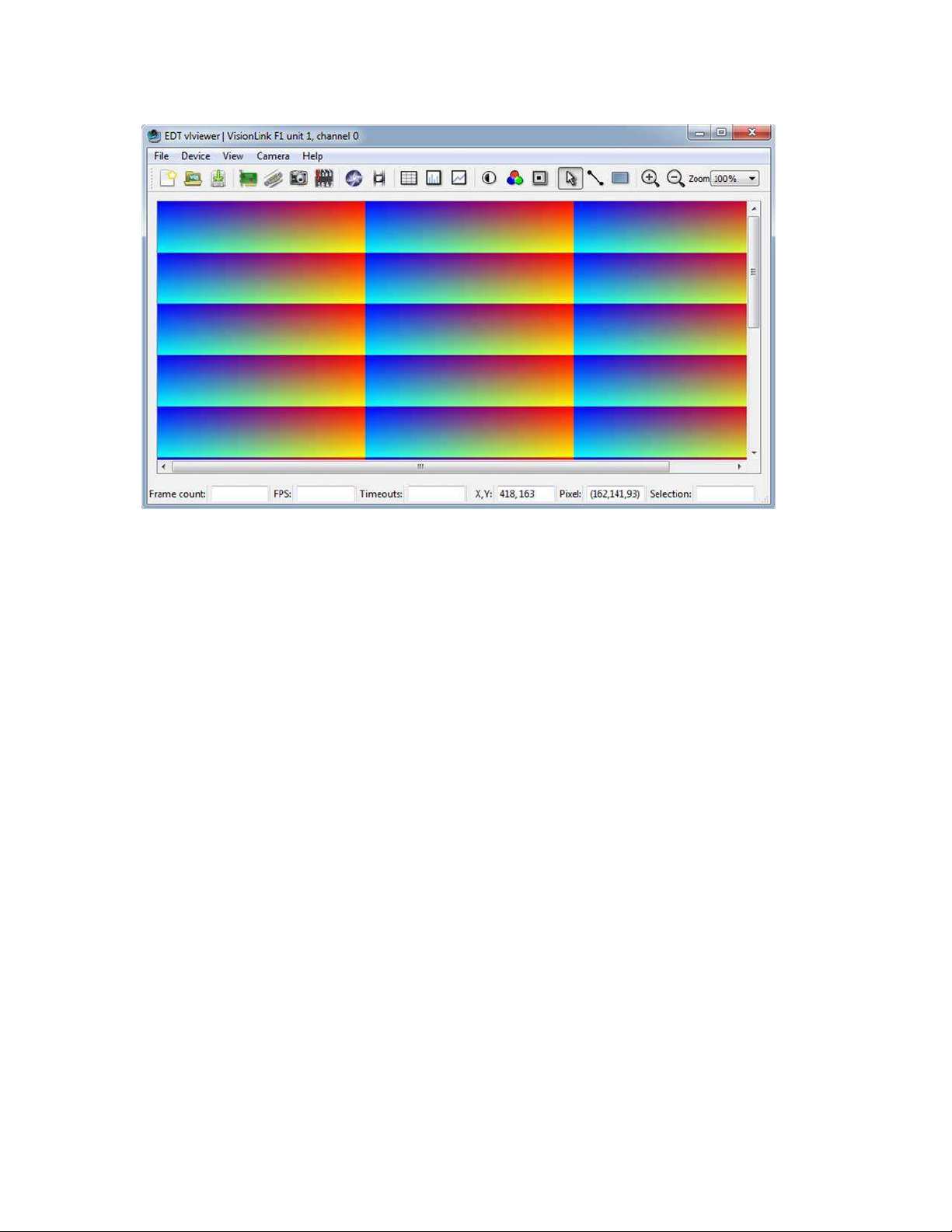
The Windows version of vlviewer is shown in Figure 1.
EDT, Inc.
2019 April 29
10
VisionLink F-series
Image Capture and Display GUI
Figure 1. Windows version –vlviewer
To run the GUI...
•
For Windows: Click the vlviewer desktop icon, or enter vlviewer at a command prompt.
•
For Linux: Compile vlviewer (see Compiling vlviewer on page 22); then, in the installation directory (see Instal-
lation on page 8),enter...
vlviewer
To invoke with other than the default (0,0) unit and channel, run...
vlviewer -pdvU_C
...replacing U with the unit number (useful if you have more than one VisionLink device) and C with the channel
number for multichannel devices (see Units, Connectors, and Channels on page 11).
For example, to run the GUI using board 0, channel 1, run...
vlviewer -pdv0_1
This example is useful if, for instance, you are using one board with two base-mode cameras and you want the GUI to
access the camera on channel 1.
NOTE InWindows, the command line is a property of the icon.To use an icon to access a unit orchannel other than 0 (the
default): copy and rename the vlviewer icon; then change its shortcut properties to use the command line with the
option -pdvU_C where U is the unit and C is the channel.
If you have not yet configured the device for your camera, select your camera or simulator from the list and click OK.
If the image window shows incorrect data (usually because the camera model has been changed since the last
configuration), select Camera > Setup and choose the correct camera model.
To access camera controls, use the GUI toolbar and menus. For details on available options, run...
vlviewer --help
...or bring up vlviewer and select the Help menu.
EDT, Inc.
2019 April 29
11
VisionLink F-series
Units, Connectors, and Channels
Units, Connectors, and Channels
This section covers how to work with multiple units, connectors, and channels, defined and used as shown in Table 4.
Table 4. Definition, usage, and enumeration
Definition
Usage and Enumeration
unit
physical board
If you install one board in your host system, the system will assign the default unit number (0) to
that board. If you install multiple boards, the system will assign a unique unit number to each
board, starting with 0 (the sequence is system-dependent). Typically, the unit number is an
argument when invoking an application (such as take or vlviewer) or a parameter passed
into one of the EDT subroutines.
connector
physical Camera
Link connector
Each VisionLink board has one or two SDR connectors and one simulation channel.
•
In base mode, each camera requires one SDR connector on the EDT board, and each con-
nector provides one channel. Therefore, in base mode, an EDT frame grabber with two con-
nectors has two channels.
•
In medium or full mode, each camera requires two SDR connectors on the EDT board. In this
case, the two connectors work together to support onechannel.
The software enumerates each SDR connector starting from the PCIe bus. So the first (primary)
connector is “0” and the next (secondary) connector is “1.” The simulator channel is “2.”
See Simulation and Testing on page 20.
channel
channel or,
sometimes,
simulation channel
Figure 2illustratesenumeration.Units(boards),connectors,andchannelsarealwaysenumeratedfrom0. Figure 2 also
shows the status indicator LEDs (see LEDs on page 12), which are enumerated in the same way.
Figure 2. Illustration of enumeration
If you are using multiple EDT boards (units), or multiple connectors on a single EDT board, the software assigns a
unique handle to represent each unit and connector. Unless you specify a different unit number, connector number, or
both, all EDT example and utility applications will default to unit 0, connector 0.
The way that you address the appropriate unit and channel will depend on what you are doing.
•
In the EDT GUI (vlviewer or pdvshow), use -pdvU_C (see Image Capture and Display GUI on page9.
•
In the EDT example and utility applications, use -u unit and -c channel (see Example and Utility Applica-
tions on page 13).
•
IntheEDT API, use pdv_open_channel(..., unit, channel).Foreach device, theopenroutinewillreturn
a pointer to the structure that represents the opened device (unit and channel); this pointer appears in EDT exam-
plesand documentation as pdv_p.Each unit / channelcombinationcanbe opened andmanipulated independent-
ly by passing the appropriate pointer to the library subroutines. For details, consult the EDT API (see Related
Resources on page 7).
LEDs
LED enumeration is 0, 1, 2, 3 (left to right
inthe board’s typicalverticalorientation).
0 1 2 3
Units & Connectors
Unit enumeration is system-dependent,
starting with unit 0.
Unit 0,
Connector 1
(secondary
connector)
Unit 1,
Connector 1
(secondary
connector)
Connector enumeration starts at 0 with
the connector nearest the PCIe bus. Unit 0, Unit 1,
Connector 0 Connector 0
(primary (primary
connector) connector)

EDT, Inc.
2019 April 29
12
VisionLink F-series
LEDs
LEDs
As shown in Figure 2, each frame grabber’s backpanel has four LEDs (0, 1, 2, 3, left to right) to show status, as below.
Table 5. LED behavior and significance
LED #
Connector #
Status
0
0
Pixel clock: on = present; off = absent
1
0
PoCL output:: on = 12V; off = GND; fast blink = error; slow blink = floating / open / sensing
2
1
Pixel clock: on = present; off = absent
3
1
PoCL output:: on = 12V; off = GND; fast blink = error; slow blink = floating / open / sensing
Serial Communication
Most cameras have a manufacturer-defined serial command set for camera control and status. To utilize this capability,
EDT boards implement serial transmit and receive using standard serial lines as defined by the Camera Link standard.
You can use serial communication in a number of ways, as discussed below.
At Initialization
As mentioned in Installation on page 8, the initialization process uses directives in a configuration file to set the board
registers and the driver variables to match your camera model and your operating mode. Additional directives
(especially serial_baud, serial_init, serial_binit, and other serial_* directives) can be used to
sendserialcommandswhenthesystemisinitialized.ThesearedescribedintheEDTCameraConfigurationGuide(see
Related Resources on page 7).
EDT provides several example configuration files that contain the serial commands needed to put a camera into the
desired mode. You can edit these commands or copy them to a new configuration file.
For suggestions, see comments in the example configuration files camera_config/genericXcl.cfg (where X is
replaced by a specific bits-per-pixel value –for example, generic8cl.cfg) in the EDT installation package.
From Command Line
The command-line utility serial_cmd, described in serial_cmd on page 15, allows you to send serial commands to
a camera and receive its response, in either ASCII or hexadecimal format. Command-line help also can be accessed
by entering serial_cmd --help.
If you wish to incorporate this functionality in your own application, see the source code provided in serial_cmd.c
in the EDT installation package.
From EDT GUI
In vlviewer, from the Camera menu, select Programming. The resulting dialog allows you to send and receive serial
commands from the camera. For details, see Image Capture and Display GUI on page 9.

EDT, Inc.
2019 April 29
13
VisionLink F-series
Example and Utility Applications
From Your Application
To see all of the routines needed for user applications to send and receive serial commands: In the EDT API (see
Related Resources on page 7), follow the link to the EDT digital imaging library, and then —under Modules at the
bottom of the page —to Communications /Control.
From Camera Manufacturer’s Application
MostCameraLinkcameramakerssupplyaWindows-basedgraphicalcameracontrolapplicationthatletsyousendand
receive serial commands using a board-specific serial dynamic link library (DLL). Your EDT installation package
provides a DLL named clseredt.dll which, per the Camera Link 2.0 specification, is installed at...
•
%PROGRAMFILES%\Cameralink\Serial (64-bit version);or
•
%PROGRAMFILES(X86)%\CameraLink\Serial (32-bitversion)
Camera GUIs typically provide some method for specifying the DLL pathname; for details, see your camera
documentation.
If it becomes necessary to rename the file or copy it to a different location, be sure to recopy any newer versions of the
file to the appropriate location when you reinstall the EDT installation package.
NOTE Some camera manufacturers' control applications do not use this DLL method but instead depend on COM port
emulation for serial communication. In such cases, use the provided COM port emulation method; for details, see
README.pdvcom in your installationdirectory.
Example and Utility Applications
EDTprovidesavarietyofexample,utility,anddiagnosticapplications.Allcanberunfromthecommand line,using Unix-
style options andarguments.
To help those developing applications, EDT provides C source code for all of the examples. The source code file is the
name of the application with a .c extension (e.g., “take.c”). Starting with the source for simple_take or
simplest_take isrecommended.
The most commonly useful options for these programs are described below. Placeholders shown in italics should be
replaced with your own values. For a complete list of usage options, at the command line, enter the application name
with the --help option to display the help message.
pciload
Used to query the boards or, optionally, to update and verify the board’s flash PROM. After installation, you may want
to run pciload with no arguments and review the output to help verify that the board and driver did install correctly.
To use pciload to update and verify the flash PROM, see Firmware: FPGA Configuration (.bit) Files on page 22.
setdebug
A debug and diagnostic utility. The options shown here may be useful to you. Options not shown here, as a rule, are
specific to driver internals and are useful (and safe) only with guidance from EDT engineers.
-u unit The unit number, if multiple boards are installed; default is 0 (first board).
-c channel The channel, on multichannel boards; default is 0 (first channel).
-d 0 Unique to setdebug. Displays current board registervalues.
-v Unique to setdebug. Displays version information for library and driver.
-h Displays full list ofoptions.

EDT, Inc.
2019 April 29
14
VisionLink F-series
Example and Utility Applications
initcam
Command-line utility that initializes the board and device driver for aspecific camera. It initializes board registers; sets
various parameters (width, height, depth, etc.) to specific values; and optionally sends serial initialization commands to
the camera from the referenced configuration file. Configuration files are in your EDT installation package under
camera_config. The EDT camera selector GUI applications (vlviewer, pdvshow) are simply wrappers to provide a
way to select the correct file, then shell out to call initcam. To initialize from your own application code, you can use
initcam.c as example code.
For a detailed description of configuration files and directives, consult the Camera Configuration Guide (see Related
Resources on page 7).
Several of the most useful options are...
-u unit The unit number, if multiple boards are installed; default is 0 (first board).
-c channel The channel, on multichannel boards; default is 0 (first channel).
-f pathname The (required) name of the configuration file to use for initialization.
For example...
initcam -f camera_config/generic8cl.cfg
take
Used toacquire images and (optionally) savethem tofiles.Though itdoes notdisplaytheimages,itdoesprovidemany
other options, making it a useful diagnostic tool. The source also shows how to change camera settings such as
integration time; tune image acquisition in certain ways; and detect errors.
Several of the most useful options are...
-u unit The unit number, if multiple boards are installed; default is 0 (first board).
-c channel The channel, on multichannel boards; default is 0 (first channel).
-b file The base name of the file in which to save the image, in Windows bitmap format
for all systems (note –in EDT software packages later than 5.3.3.3, this option
always will create files in Windows bitmap format, regardless of which operating
system you are using). If only one image is taken, this is the filename; otherwise a
two-digit number is appended to each file, starting with 00. The appropriate suffix
is automaticallyadded.
-f file The name of the file in which to save the image, in raw format. The file includes
onlyraw image data, with no formatting information.
-l loopcount The number of consecutive pictures you wish to take. The default is one.
-N numbufs The number of ring buffers (default is 1). A ring buffer is a portion of host memory
preallocated for DMA and used in round-robin fashion. A setting of four optimizes
pipelining —one ring buffer currently acquiring data, one ready for data, one
getting ready, and onebackup.
-v Turns on verbose mode. The default isoff.
As an example, to acquire 100 images as quickly as possible using four ring buffers, without saving to files, enter...
take -N 4 -l 100
As another example, if you have one VisionLink board connected to two base-mode cameras and you wish take to
use the camera on channel 1, enter...
take -u 0 -c 1 -N 4 -l 100

EDT, Inc.
2019 April 29
15
VisionLink F-series
Example and Utility Applications
simple_take
Showshowtouse the APItoacquireimages from acamera linked to theboardand(optionally)savetheimagesto files.
To add image acquisition to an application, EDT recommends starting with this example, which shows how to use the
ring buffer routines to improve performance by pipelining image acquisition and processing.
Several of the most useful options are...
-u unit The unit number, if multiple boards are installed; default is 0 (first board).
-c channel The channel, on multichannel boards; default is 0 (first channel).
-b file The base name of the file in which to save the image. If only one image is taken,
this is the filename; otherwise a two-digit number is appended to each file, starting
with 00. The appropriate suffix is automatically added.
-l loopcount The number of consecutive pictures you wish to take. The default is one.
-N numbufs The number of ring buffers —by default, one. (A ring buffer is a portion of host
memory preallocated for DMA and used in round-robin fashion.) A setting of four
optimizes pipelining —onering buffercurrently acquiring data, oneready for data,
one getting ready, and onebackup.
For example, to acquire four images as fast as possible using four ring buffers, saving each to files named
picture00.bmp through picture03.bmp, enter...
simple_take -N 4 -l 4 -b picture
simplest_take
The simplest example application, showing only how to open the device, acquire an image, check for timeouts, and
close the device. For simplicity, there is no optimization for pipelining, no processing or extended error checking.
simplest_take reports a successful image acquisition, or any errors that occurred —useful for testing.
simple_sequence
Like simple_take but, instead ofcapturing and saving one file at a time, itcapturesafinitenumber ofimages(limited
to available memory) into memory and then writes them all out at once.
serial_cmd
Sends serial commands to a camera through the board, using calls to routines in the API. By default, the application
starts in command mode: the final argument to serial_cmd is the command to send to the camera. Delimit this
command with either single or double quotation marks, but be consistent. For example...
serial_cmd "MDE?"
If you omit the command argument, the application enters interactive mode, in which you can type one command per
line. To quit the application, enter Control-C.
Several of the most useful options are...
-u unit The unit number, if multiple boards are installed; default is 0 (first board).
-c channel The channel, on multichannel boards; default is 0 (first channel).
-x Treats the command argument as a hexadecimal number, which is sent to the
camera without terminating nulls or carriage returns. The default is ASCII with a
terminating carriage returnadded.
For example (command mode usage)...
% serial_cmd "MDE?" (Redlake "Query Mode"command)

EDT, Inc.
2019 April 29
16
VisionLink F-series
Triggering
MDE TR (camera response)
%
For example (interactive mode usage)...
% serial_cmd
>MDE? (Redlake "Query Mode"command)
MDE TR (camera response)
>
% serial_cmd -x (for hexadecimalarguments)
> 03 06 02 (camera-dependentcommand)
> Control-C (end the program)
To access a camera on channel 1,enter...
% serial_cmd -u 0 -c 1 "MDE?"
(Redlake "Query Mode" command)
MDE TR (camera response)
%
dvinfo
Gathers board-specific and system-specific technical data, runs various diagnostics, and writes the results to
dvinfo.out in the current directory. Use the resulting ASCII text file to diagnose problems yourself, or send the file
to EDT for technical support.
To run dvinfo...
1.
Connect and power on thecamera.
2.
If possible, initialize the board with initcam orvlviewer.
3.
Close all VisionLink applications (including initcam, vlviewer, pdvshow,etc.).
4.
Run dvinfo. If multiple boards are installed, you may find it helpful to add the optional flag...
-u unit
...replacing unit with the unit number. The default is 0 for the first board (for details, see Units, Connectors, and
Channels on page 11).
Triggering
EDT provides configuration files for most cameras running in freerun mode (i.e., no triggering), and also some files for
cameras running in triggered or pulse-width modes. This section describes common triggering modes supported by
EDT, with abbreviated information on configuration file directives and subroutines. For more complete information,
consult the EDT Camera Configuration Guide and API (see Related Resources on page 7) and your camera manual.
NOTE If you have issues, consult Troubleshooting on page24.
No Triggering –Freerun (Continuous)
In this mode, the camera acquires images continuously without initiating or passing through any trigger or expose
signals. Exposure time is controlled by the camera and typically is set via a camera-specific serial command.

EDT, Inc.
2019 April 29
17
VisionLink F-series
Triggering
For area or line scan cameras, use the following information...
Configuration file directives MODE_CNTL_NORM: 00 (default)
serial_init: Camera-specific serial command(s) to initialize for freerun. Use as
needed (usually not needed because most cameras power on in freerun by default).
serial_exposure: Camera-specific serial command to set the exposure time; for
example, use "set" for the Dalsa 1M60.
API subroutine pdv_set_exposure(), Camera-specific range and units.
Triggered by EDT Board (On-Demand)
In this mode, the camera sends a 1-millisecond trigger pulse over a camera control line, typically CC1, each time a
request for acquisition is made –such as when pdv_start_images() is called. Exposure time is controlled by the
camera, and typically is set via a camera-specific serial command.
For area or line scan cameras, use the following information...
Configuration file directives MODE_CNTL_NORM: 10
method_camera_shutter_timing: AIA_SER (default)
serial_init: Camera-specific serial argument to enable triggering via CC1.
serial_exposure: Camera-specific serial command to set the exposure time; for
example, use "set" for the Dalsa 1M60.
API subroutine pdv_set_exposure(), Camera-specific range and units.
Triggered by EDT Board (Fixed Period)
In this mode, the board sends a fixed periodic trigger signal over a camera control line, typically CC1, for each frame or
line of image data.
For area scan cameras, use the following information...
Configuration file directives MODE_CNTL_NORM: 10
CL_CFG2_NORM: The default is 00, which selects current channels counter; use 80 to
select other channels counter (i.e., if synchronized trigger output is desired).
method_frame_timing: FMRATE_ENABLE
frame_period: Microsecond units (range 0–16777215).
photo_trig: 1
serial_init: Camera-specific serial command to enable triggering via CC1.
API subroutine pdv_set_frame_period(), Microsecond units (range0–16777215).
For line scan cameras, use the following information...
Configuration file directives MODE_CNTL_NORM: 10
CL_CFG_NORM: 14
CL_CFG2_NORM: The default is 00, which selects current channels counter; use 80 to
select other channels counter (i.e., if synchronized trigger output is desired).
xregwrite_16: 40
method_frame_timing: FMRATE_ENABLE
frame_period: Microsecond units (range 0–16777215).
serial_init: Camera-specific serial command to enable triggering via CC1.
API subroutine pdv_set_frame_period(), Microsecond units (range0–16777215).

EDT, Inc.
2019 April 29
18
VisionLink F-series
Triggering
Pulse-Width Triggered (Controlled or Level)
In this mode, exposure duration is determined by how long the camera control line, typically CC1, is held TRUE (high).
For area scan or line scan cameras, use the following information...
Configuration file directives MODE_CNTL_NORM: 10
method_camera_shutter_timing: AIA_MCL
default_shutter_speed: Millisecond units (range 0–25500).
serial_init: Camera-specific serial command to enable pulse-width exposure control
via CC1.
API subroutine pdv_set_exposure(), Millisecond units (range 0–25500).
For line scan cameras with very fast shutters accepting exposure times in microseconds, use the argument 100US for
method_camera_shutter_timing in order to set pdv_set_exposure() for microseconds, not milliseconds...
Configuration file directives MODE_CNTL_NORM: 10
method_camera_shutter_timing: AIA_MCL_100US (to change to
miicroseconds)
default_shutter_speed: Microsecond units (range 0–25500).
serial_init: Camera-specific serial command to enable pulse-width exposure control
via CC1.
API subroutine pdv_set_exposure(), Microsecond units (range 0–25500).
External Trigger Direct to Camera
In this mode, a trigger is sent from an external source directly to the camera, bypassing the board. The board can be
configured as in freerun mode; however, be aware of the Note on Software Timeouts below.
For area scan or line scan cameras, use the following information...
Configuration file directives MODE_CNTL_NORM: 00
user_timeout: See Note on Software Timeouts below.
API subroutine pdv_set_timeout(), Millisecond units (range 0–65535).
Note on Software Timeouts
If your application experiences timeouts it is safe to ignore them, but if you do, you won’t know if they were caused by
a problem or by the gap length between triggers. To avoid timeouts due to gap length, do one of the following...
•
If the maximum gap length between triggers is known: Enter a user_timeout value which exceeds that value.
•
If application blocking is acceptable: Enter a user_timeout value of zero (user_timeout: 0)to tell the ap-
plication never to time out but instead to keep waiting for the next trigger.
External Trigger Passthrough
In this mode, a trigger is sent from an external source directly to the board, which passes it to the camera on a camera
control line, typicallyCC1.

EDT, Inc.
2019 April 29
19
VisionLink F-series
Triggering
For area scan cameras, use the following information...
Configuration file directives MODE_CNTL_NORM: A0
xregwrite_16: Use optionally to select trigger input. The default is trigger input 0 but if
trigger input 1 is desired, use 80. For details, consult the Firmware Addendum, register 0x10
(see Related Resources on page 7).
user_timeout: See Note on Software Timeouts in External Trigger Direct to Camera.
serial_init: Camera-specific serial command to enable triggering via CC1.
API subroutine pdv_set_timeout(), millisecond units (range 0–65535)
For line scan cameras using normal external trigger passthrough, use the following information...
Configuration file directives MODE_CNTL_NORM: A0
CL_CFG_NORM: 04
continuous: 1
xregwrite_16: Use optionally to select trigger input. The default is trigger input 0 but if
trigger input 1 is desired, use 80. For details, consult the Firmware Addendum, register 0x10
(see Related Resources on page 7).
photo_trig: 1
user_timeout: See Note on Software Timeouts in External Trigger Direct to Camera.
serial_init: Camera-specific serial command; enables triggering via CC1.
API subroutine pdv_set_timeout(), millisecond units (range 0–65535)
For line scan cameras using external trigger passthrough with acquisition arming (not supported for area scan), the
information is similar to the above. A TTL signal is sent from an external source to the board via trigger 0 and then is
passed from the board to the camera via a camera control line (typically CC1) to trigger line output. Additionally, a
secondary TTL signal is sent from an external device to the board via trigger 1, which arms the board for acquisition.
For example, the “A” pulse from an encoderis input on trigger 0 and passed throughto the camera via acamera control
line (typically CC1), thus triggering a line to be output from the camera. Additionally, the index pulse from the encoder
is input on trigger 1 to arm or rearm the board for acquisition, ensuring that acquired images are synchronized to the
encoder’s rotational position. The acquired image always starts at the encoder index. Use the following information...
Configuration file directives MODE_CNTL_NORM: A0
CL_CFG_NORM: 04
CL_CFG2_NORM: 04
continuous: 1
photo_trig: 1
user_timeout: See Note on Software Timeouts in External Trigger Direct to Camera.
serial_init: Camera-specific serial command to enable triggering via CC1.
API subroutine pdv_set_timeout(), Millisecond units ((range 0–65535)
External Triggering Pins
The pins to which you connect the trigger source are shown in Appendix B: Diagrams –Boards and Cabling.
With two cameras, trigger 0 can trigger both cameras, or triggers 0 and 1 can trigger cameras 0 and 1 independently;
for details on setting the bits, refer to the directive xregwrite_16 or consult the Firmware Addendum (see Related
Resources on page 7), register 0x10, bit 7.
Fire the trigger byapplying a TTL signal lasting at least 200 nanoseconds to these pins, which in turn will output a signal
of the appropriate level to a camera control line, typically CC1.
EDT, Inc.
2019 April 29
20
VisionLink F-series
Simulation and Testing
The two pins of each trigger drive a Fairchild HCPL062N optocoupler through a 130-ohm series resistor. This
optocoupler is provided to allow coupling to electromechanical systems in which major ground spikes can occur when
electrical devices such as motors, for example, turn on or off.
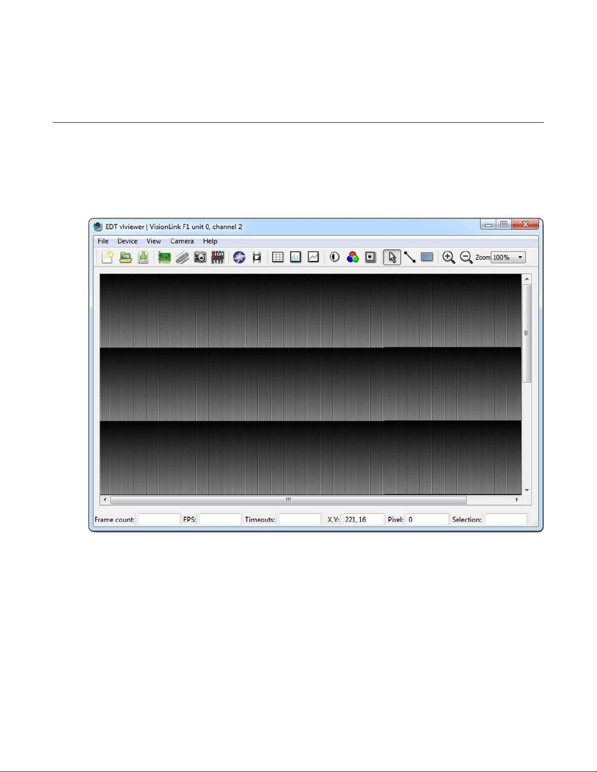
Simulation and Testing
In addition to the physical channels 0 and 1, each VisionLink frame grabber has a "phantom" channel 2 that reads self-
generated sample data, useful for testing the board hardware and software with no camera attached. This channel uses
a simple counter to generate 16-bit pixel data; the pixels start as black and fade to white, as shown in Figure 3.
Figure 3. Simulated channel 2 test image in vlviewer
To use the channel 2 simulator with vlviewer...
1.
Start the application with, forexample...
vlviewer -pdv0_2
2.
Select the Camera > Setup menuitem.
3.
Select the desiredconfiguration.
This manual suits for next models
1
Table of contents
Popular Media Converter manuals by other brands


TV One
TV One C3-540 CORIOmaster user guide

Technica Engineering
Technica Engineering 1000Base-T1 SPY mini user manual

Tripp Lite
Tripp Lite N785-INT-SC-SM owner's manual

AVPro Edge
AVPro Edge AC-SC2-AUHD-GEN2 user manual

3One data
3One data 1100 user manual

Planet
Planet IGT-900 Series Quick installation guide