ACEK9 HA-2520 User manual

Model HA-2520
Patent # 7,081,811
K9 Heat Alarm® Pro
With Protective Relay Module
Installation Manual
Refer to the vehicle specific instructions sheet during install.
Life Safety Equipment
It is vital that all Safety Features are installed, tested and working properly.
Special Attention needs to be made to Power and Safety Warnings.
This Life Safety Equipment must be installed to Emergency Vehicle Up-
fitting Standards!
Radiotronics Inc.
1315 SW Commerce Way
Stuart Fl 34997
Phone: (772) 600-7574
Fax (772) 600-7012
www.AceK9.Com

Contents
Warnings and Safety information
Introduction Page 1
Safety Information Page 2
Installation Page 3
Step 1 Planning Page 3
Step 2 Control Head installation Page 3
Step 3 Intelabox installation Page 3
Step 4 Protective Relay Module Connections Page 4
Battery power
Ground
PRM to IntelaBox
Installing Heat Alarm Alert Features Page 5
Step 5 Horn Alert Feature Page 6
Step 6 Lightbar / Strobe Alert Page 7
Step 7 Siren Alert Feature Page 7
Step 8 Window Drop Feature Page 8
Step 9 Temperature Sensors Page 8
Step 11 Heat Alarm ignition power Page 9
Step 12 Stall Sensor option Page 9
Step 13 Optional add on modules Page 9
Step 14 Finish Install and Test System Page 9
Introduction
K9 Heat Alarm® Pro includes our vehicle monitoring system and Alert Options:
S.O.S. Sound Horn Activation, Dual Window Drop, Emergency Light Activation, and
Siren Activation.
HP-2520 Standard Parts
1 - IntelaBox
1 - Control Head
1 - Control Head Cable
1 - Manuals (Owners, Install and Vehicle Specific)
1 - Installation Hardware Kit
2 - Temperature Sensor
1 - Protective Relay Module
1 - Window Drop Module
Standard Outputs
1 - Horn Activation (choice of + or -)
1 - Siren Activation (choice of + or -)
1 - Light Activation (choice of + or -)
1 - Window Drop Activation (+)
Optional Accessories (Purchased separately)
AceWatchDog (Cellular Phone App) Pager System
Stall Sensor Fan Kits
Carbon Monoxide Detector. Smoke Detector.
Auto Starter Software (includes stall sensor and output activation).

2
This manual is used in conjunction with the vehicle specific
instructions sheet.
If the make, model and year do not match the vehicle instructions or the equipment
is being reinstalled in new vehicle Contact AceK9.Com Service Department.
When contacting AceK9 service, have your SERIAL NUMBER available.
________________________________________________________________________________________
Safety Warnings and Installation Information
Life Safety Equipment
It is vital that all Safety Features are installed, tested and working properly at the
time of installation.
While installing, special attention needs to be made to power and safety warnings.
This Life Safety Equipment must be installed to Emergency Vehicle Up-fitting
Standards! Refer to the vehicles service manual and modifiers guides during installation.
The window drop module is designed for vehicles with a rear seat K9 Transporter
and window guards, to contain the K9 and prevent unauthorized access to the vehicle. If
dropping un-guarded windows anti-theft system, equipment vault, and K9 transporter are
recommended.
________________________________________________________________________________________
Warning: Install Electronics modules in dry locations
(Except Weather resistant, Sealed Window Relay Modules designed for in door installation)
NEVER install in the following locations, which are frequently subject to wet conditions'
On the floor boards.
Under the floor mats.
Under K9 transporter.
In engine compartment.
Against the air conditioner
housing/vents.
Under seats.
Under equipment consoles cup holders.
Connections exposed to moisture should be protected.
________________________________________________________________________________________
Safety Warnings
Do not install equipment in areas that interfere with vehicles safety systems (airbags, seat
belts). Use caution when drilling or installing screws, avoid wiring, fuel lines, or other
equipment that might be behind the surface.
Never run wires through a drilled hole without a grommet, wires chaffing against metal will
overtime cause malfunctions or vehicle fire. When using a grommet seal to prevent water
entry into vehicle. (use a sealant appropriately related for the location)

3
Installation
This manual is written to provide the information necessary for safe and reliable operation of
this Life Safety Equipment. Read the Vehicle Specific Instructions to guide you
thru the install.
T
T
Th
h
hi
i
is
s
s
p
p
pr
r
ro
o
od
d
du
u
uc
c
ct
t
t
i
i
is
s
s
s
s
so
o
ol
l
ld
d
d
f
f
fo
o
or
r
r
a
a
a
s
s
sp
p
pe
e
ec
c
ci
i
if
f
fi
i
ic
c
c
v
v
ve
e
eh
h
hi
i
ic
c
cl
l
le
e
e,
,
,
i
i
in
n
ns
s
st
t
tr
r
ru
u
uc
c
ct
t
ti
i
io
o
on
n
ns
s
s
a
a
ar
r
re
e
e
i
i
in
n
nc
c
cl
l
lu
u
ud
d
de
e
ed
d
d.
.
.
S
S
Sp
p
pe
e
ec
c
ci
i
ia
a
al
l
l
p
p
pa
a
ar
r
rt
t
ts
s
s
m
m
ma
a
ay
y
y
a
a
al
l
ls
s
so
o
o
b
b
be
e
e
i
i
in
n
nc
c
cl
l
lu
u
ud
d
de
e
ed
d
d.
.
.
STEP 1 Planning Consult with the end user
Determine a suitable mounting location for the Control Head. The Head should be easily
visible to the K9 Handler.
If a fan kit was purchased determine the preferred location, usually in a rear door
window, blowing air across the K9.
Have end user review Menu settings and customize them to their requirements.
The install will vary greatly depending on the customer preferences, vehicle, and equipment.
Review these instructions and the vehicle specific install supplement to get an overview
of the equipment placement, wiring and connections. Also review the Installation
Information for each of the Heat Alarm Alert Options that you are installing. Make
connections following the order outlined below. Consider where connections are made, run
wires in groups. Planning will speed installation. Parts and setup will vary by vehicle. see
Vehicle Specific Information
STEP 2 Control Head installation
Mount securely in a location that is dry and visible to the K9 handler. Plug the control head
cable into the head.
STEP 3 Intelabox installation
Mount the IntelaBox in a location that allows easy access
Find a DRY location where it is easily serviceable for upgrades and programming.
Route the Control Head Cable to the Intelabox. Attach the cable, be sure that the cables
(RJ45) connectors go in straight and the cable is not kinked. Do not run control head cable
parallel to transmitting antenna cables.

4
STEP 4 Protective Relay Module (PRM) Connections
The Protective Relay Module is the output controller for heat alarm options and accessories.
Locate the Protective relay module near the Intelabox.
Connect the IntelaBox Heat Alarm Option Cable (Gray Cable with black connector)
to Protective Relay Module (PRM).
Connect the IntelaBox 18 Gauge Red Male Wire W/3A fuse to the Red Female wire off the
PRM.
Attach the PRM Black Ground (PIN 12) wire to a chassis ground.
Attach PRM's Red Battery wire to uninterrupted Battery Power. This connection point
must be rated to supplying 40A of power. Attach 40A Fuse at connection point.
Battery connection must be direct. Do not use a device that automatically
removes power to vehicle and connected system that notify the K9 handler when
the system activates.
This system has features designed to operate with the IGNITION OFF.
When power is connected, the head will power up briefly and turn itself off. Continue with
install.
Installing K9 Heat Alarm® Pro alert features

5
Connecting outputs from the Protective Relay Module
The Protective Relay Module Provides output wires to activate standard horn,
lights, and siren activation, and the window drop feature. To accommodate a
variety of setups a choice of low current ground triggers or positive activation
are provided.
DO NOT REPLACE FUSES WITH A FUSE OF HIGHER VALUE
A three pin Auxiliary Options Connector is also provided for add on options. Smoke and
Carbon Monoxide Detectors utilize this connector. These options connect in line (Daisy Chain)

6
STEP 5 Horn Alert Feature
A Choice of Positive or Negative Outputs are provided
Consult your Vehicle Specific Information for horn polarity , wire color, and
connection location
When other equipment is attached to the horn wire, always place the K9
connection closest to the horn.
5A For Horn Ring Connection. (-)
AceK9 Wire Color: Orange
Wire Connects to the vehicles horn ring wire.
Polarity: The Orange Wire provides a negative low current signal used to activate the
factory horn relay. This signal provides a ground trigger duplicating the traditional horn ring
switch in the horn pad.
Location: In vehicles with grounding horn switches the wire runs down the steering column
to the horn relay or a Control module.
Test: The vehicles horn wire will show ground when the horn pad is pressed (0 volts) and
power when not active (12+ volts).
Connection: Splices into vehicles horn ring wire.
5B For Connection at Horn (+)
AceK9 Wire Color: Orange/Yellow and Orange/Red Wires
Common on Chrysler, Dodge, and Jeep Vehicles. (See Vehicle Specific Information)
Polarity: Orange/Red wire provides positive power to activate the vehicles horn, The
Orange/Yellow wire Isolates the power to prevent damaging back feed to the vehicles
computer and allows normal activation of the of horn.
Location: Under Hood at the horn wiring.
Test: The vehicle horn wire will show Power when the horn pad is pressed (12 volts)
Connection: Solder and Heat Shrink Connections.
1 Cut the Vehicles horn wire.
2 Connect the K9 Orange/Red to the Horn side.
3 Connect the K9 Orange/Yellow to the fuse block side.

7
STEP 6 Light Bar/Strobe Alert Feature
“TIP” Some Light/Siren Controllers allow for programming of both light and siren activation off one input.
A Choice of positive or negative output is provided.
AceK9 Wire Color: Green (-)
Green/Red (+)
Green (-) wire provides a negative output (Low Current Ground Trigger 0.75A)
Green/Red (+) wire provides a positive output (12V+ when triggered Fused at 15A Max)
Light Controler Input Method.
Connection: Consult the instructions provided by the controller manufacturer for polarity
and programing.
Lights Using Standard 12V light methods (+)
Lights activated by a switch or light controller's isolated Positive outputs.
Connection: Connect the Green/Red wire to the light side of the switch or controller.
(12V+ when triggered Fused at 15A Max)
STEP 7 Siren Alert Feature
AceK9 Wire Color: (Violet - or Violet/Red +)
A Choice of Positive and Negative Outputs are provided.
Violet wire provides a negative output (Ground Trigger 3A Max)
Violet/Red wire provides a positive output (B+ when triggered Fused at 15A Max)
Never connect to wire of emergency vehicles high power siren speaker.
Siren using programmable input.
Violet (-) or Violet/Red (+)
Connection: Most siren controllers provide a remote input to activate a siren tone.
Consult the instructions provided by the controller manufacturer for polarity and programing.
Siren using a 12V car alarm speaker. (+)
Connection: Violet/Red wire to positive side of 12V siren speaker. Attach the speaker’s
ground wire to a good ground.

8
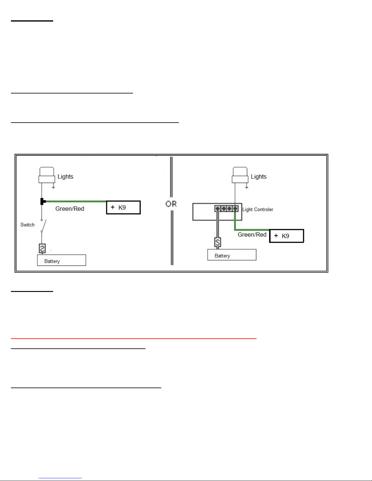
STEP 8 Window Drop Feature
Refer to Vehicle Specific Instructions for window down wire colors and locations.
Using the vehicle specific information as a guide, follow the instructions packed with your
window drop module.
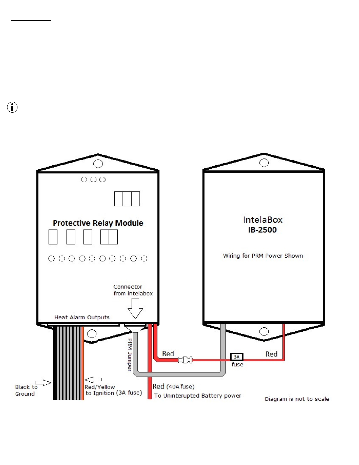
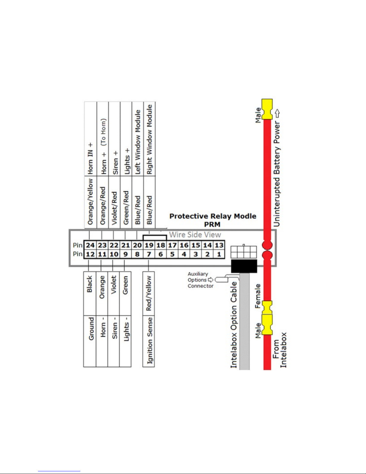
The Protective Relay Module’s Blue/Red wires supply power to the Window Drop
Modules. The Window drop modules are weather resistant Sealed Relay Modules “SRM”
designed to allow placement inside of doors.
The window drop module is designed for vehicles with a rear seat K9 Transporter and
window guards, to contain the K9 and prevent unauthorized access to the vehicle. If dropping un-
guarded windows anti-theft system, equipment vault, and K9 transporter are recommended.
Weather Sensitive Window Switches. When installing K9 Transporters' that replace factory
door panels, the switch should remain outside of the door skin, between vapor barrier and kennels
door panel. Cover switches with a plastic bag, opening pointing down, tied to allow condensation to
exit the bag.
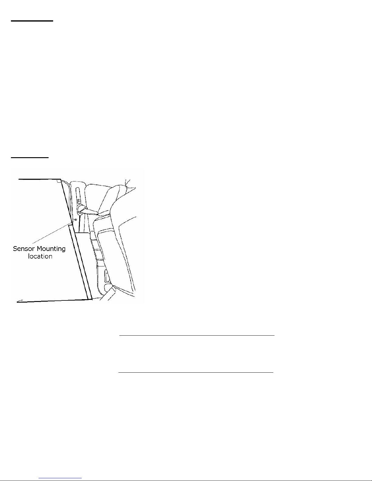
STEP 9 Temperature Sensors Mounting
Never where the K9 can damage the Sensors.
Never within 12 inches of floor or headliner.
Never in direct sunlight.
Never directly in front of air vent.
Never near equipment that radiates heat.
Never behind trim.
Place sensors in good air flow entering the
kennel
DO NOT HEAT TEMPERTURE SENSORS WITH HEAT GUN
OR FLAME
!
The sensors should be set up to monitor the area
where the K9 is housed. Sensor location may vary with
vehicle setup and operation.
The Temperature Sensor cables are over 15 feet long so they can be adjusted to the most
effective locations.
Sedans or Pick Up Trucks. with K9 transporter behind the front seats.
Mount one temperature in the airflow entering the transporter at front of the K9 transporter
on each side. A popular setup is attaching the sensors to each pillar trim (one on each side)
as long as there is good airflow into the Transporter.
Sport Utility and Wagons. with K9 transporter behind the front seats.
Mount one Temperature sensor outside of the Transporter, approximately midway up in good
airflow, in front of the K9 Transporter and the other in opposite corner, in back of the K9
Transporter, in good air flow. If area behind transporter is isolated from airflow the Sedan
method may be more appropriate.
Portable Kennels. When using a portable kennel mount the sensors cattycorner to get the
best average Temperature.
Note: Averaging must be turned off if motioning multiple canines in separated
locations.

9
STEP 10 Heat Alarm Ignition Power
Red/Yellow (pin 7)
From the Protective Relay Module connect the Red/Yellow Ignition wire to the police package
ignition point, or switched Ignition Power point on the Vehicle’s fuse panel. Ignition must
be connected for proper operation of K9 Heat Alarm®
Ignition and Power Warnings
Do not use devices that remove power to vehicle systems, alert features of this
product or emergency warning systems that it activates.
Alarms, Auto Starters, Antitheft Devices or any systems that shut off ignition
power, The K9 Heat Alarm power MUST be set up as to requite manual shut down
by the person responsible for the K9. Use settings
“On/Off Manually”
“Car On Manually off”
“No K9 Left Behind” [if purchased and installed]
STEP 11 Stall Sensor Option Sold Separately, required for auto start add on.
The stall sensor makes it easy to detect an engine stall. The sensor detects the energy
emanating from the alternator to determine that the engine is running. Mount the stall
sensor against the metal alternator housing, over visible coils. Use heat rated cable ties or
hardware. Route the stall sensor wire through the firewall to the IntelaBox. If you have to
drill a hole, use the supplied grommet, seal with silicone (not supplied). Cover the stall
sensor cable with heat rated wire loom, avoid contact with moving parts and hot exhaust
parts. (the stall sensor needs to be enabled in the Menu)
VERIFY that the stall sensor functions well after the vehicles battery is fully charged and
under minimal load. Run vehicle. The LED on the Sensor is lighted red when the vehicle is
stalled or not running.
“Tip” Idle the vehicle till battery is fully charged, If the light turns red when the vehicle is
running it may need to be repositioned. Flipping the sensor on its side may improve function.
Step 12 Optional add on modules
Connect any add on accessories purchased with system. See instructions included with
accessory. Do not attempt to connect items not approved for use with this system. See the
Installation Manual(s) for details. Use only accessories designed for Acek9.com products.
Heat Alarm test on next page

10
Step 13 Test Heat Alarm portion of the System
Check your settings, the Default Hot Temperature setting is 90 Degrees Fahrenheit.
(32◦c), The Stall monitor should be enabled only if a stall sensor has installed.
To review or change these settings enter Menu mode See the User Guide.
Test Procedure for K9 Heat Alarm Pro HA-2520
1) Power. The Default Power Settings is Heat Alarm ON with Ignition. When Ignition is
turned ON, the Heat Alarm will power up.
2) System Status. Observe the Temperatures and Vehicle’s Battery Voltage. The Hot Status
light will be illuminated when the Displayed Temperatures are below the Heat Alarm Hot Set
Point and the System in not in Snooze Mode.
3) System Output Test. Press the MENU key (for a second) to review or change the
Feature Settings or Power Settings. Use the arrow keys to scroll through the Menu. The last
Menu choice is "System Test", Press OK to start test of all the installed Heat Alarm Alert
options. Verify that ALL the installed Heat Alarm Alert Options worked. Follow remaining
prompts to check control head function.
*New AceWatchDog systems need configuration by the end user. See AceWatchDog
instructions to verify that it’s connected to the network.
4) Test Temperature Sensors. With the Hot Status light illuminated, Turn the Vehicle’s
Climate Control to the Heat Position to manually raise the Temperature inside the vehicle.
Monitor the Temperatures displayed on the heat alarm and confirm that the alarm activates
when the Hot Set Point is reached (Center Temperature is the average of left and right
sensors when the Average Temperature exceeds the hot or cold set points the alarm will
Sound after the Pre Alert.) Return the Vehicles Climate Control to the appropriate position.
DO NOT HEAT TEMPERTURE SENSORS WITH HEAT GUN OR FLAME TO TEST!
If any of these tests fail please check the installation.
Contact AceK9.Com Support with the Serial Number, Call 772-600-7574
Be sure K9 handler receives a copy of the User Manual.
Acek9.com Two (2) Year Limited Warranty
For details visit http://www.acek9.com

11
Trouble Shooting
Communications Error, no power to head, Display flickers and beeps continuously.
Check Control head cable for damage
Check that connectors are fully inserted
Check that cable is not running parallel to transmitting antennas
On units that have been in service, check for corrosion or foreign material.
Check power and ground to the PRM and that the IntelaBox is plugged in to the PRM.
Replace Control head cable, the cable is straight thru cat 5 style cable.
Alarm Displays Snooze Mode
Alarm is in snooze mode. Start up snooze mode allows the K9 Handler time to start the
vehicle, allow the Temperature in the vehicle to reach a safe level, and resolve any alarm
conditions. When the vehicle is running and the Temperature is at a safe level the status light
will turn on indicating monitoring of Temperature. (see owners manual)
Stall Sensor Alarm while driving or idling.
Stall sensors adjustment is needed, check location of sensor it needs to be located over coils
in the alternator (see install manual) Note: if a sensor was not purchased, stall monitor
needs to be Disabled in Menu.
Temperature Sensors Show Different Readings
Display Shows Temperatures as Left, Average (in center),and Right
Sensors reading will vary with location and conditions. If it is necessary to prove the
accuracy of the sensors by place both sensors together in the same location, they will be
within less than one degree of another. (allow the sensors some time to adjust).
Sensor reading differences are caused by the following. (See install manual for placement)
Sun heating the car body.
Air conditioning flow.
Open windows or air leaks.
Sensors not in good airflow.
(772) 600-7574
E-Mail Service@AceK9.com
Hours of operation Monday thru Friday
8:00am to 4:30pm EST
All rights reserved.AceK9.Com

12
Blank Page
K9 Heat Alarm Pro With Protective Relay
Module
INSTALL MANUAL

13
This manual suits for next models
1
Table of contents