Acer IDUR User manual

IDUN Housing
1
1 Introduction
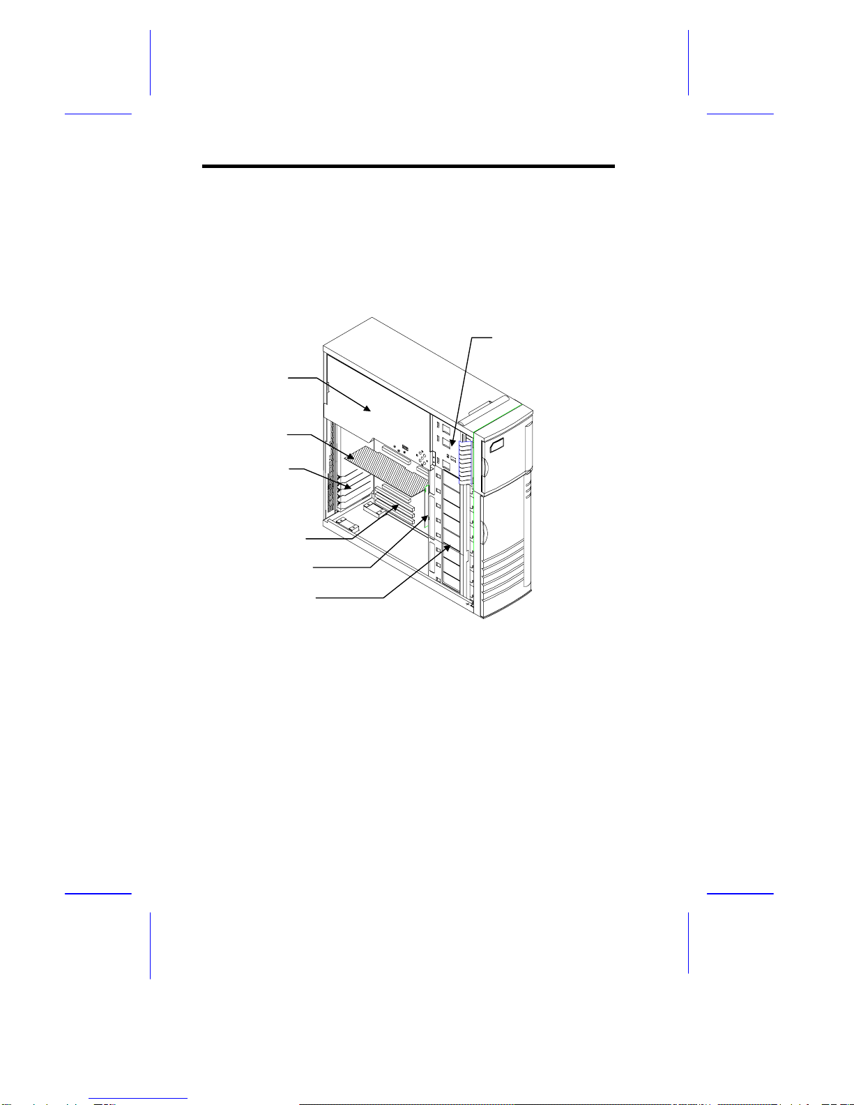
This installation guide describes the features of the IDUR housing and tells
you how to install the basic system components such as disk drives, system
board, or expansion boards. Descriptive illustrations accompany the
installation procedures.
If you receive a complete system, the basic
components are already installed.
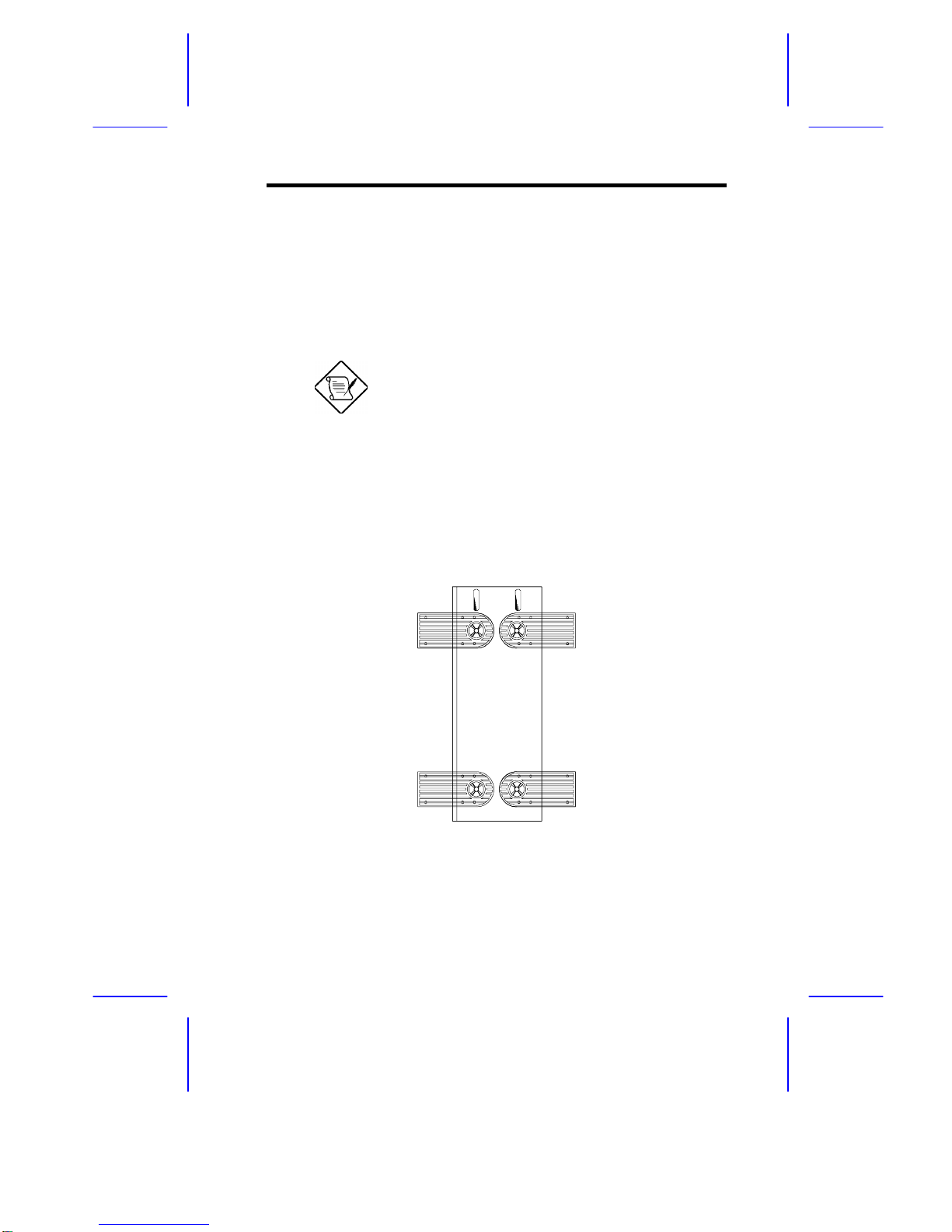
2 Positioning the System Housing
2.1 Standalone System
For a standalone system, rotate the legs outward to stabilize the housing.

2
Installation Guide
2.2 Against a Wall
Fans Facing a Wall
When standing the housing with the fans facing a wall, leave a space of
5~10 cm from the wall to allow air circulation, then position the legs as in
Figure A.
Fans Facing Out
When standing the housing with the fans facing out, you can put the system
close to the wall and position the legs as in Figure B.
Fans Fans
5~10 cm
Figure A Figure B

IDUN Housing
3
3 Transporting the System
The housing has a handle on top and two wheels behind the feet to facilitate
moving to short distances.
Rotate the feet inward before moving the housing.
When transporting the housing, pull out the handle, at the same time lifting
the unit front a few inches from the floor. Slide the housing forward with the
wheels supporting the rear.

4
Installation Guide
4 Features
4.1 Front Panel
Keyloc
k
Hard Disk Drive LE
D
Power LE
D
5.25-inch Drive Ba
y
3.5-inch Driv
e
Power Switch
SCSI Hard Disk Drive Tray
s

IDUN Housing
5
4.2 Rear Panel
Power Supply Bay
s
Power Socket 1
Keyboard Por
t
Mouse Port
Video Por
t
Parallel Port
RJ-45 Connecto
r
Expansion Slots
SCSI Expansion Slo
t
USB Connecto
r
Power Socket
2

6
Installation Guide
4.3 Internal Structure
The following figure shows the housing internal structure and some of the
basic system components.
Power Supply
Metal Plate
(covering two
redundant
power supply
modules)
Expansion Slot
Brackets
System Boar
d
Backplane Boar
d
SCSI Drive Trays
3.5-inch and 5.25-inch
Drive Bays
CPU Boar
d

IDUN Housing
7
5 Opening the Housing Panels
5.1 Upper Front Panel
Hold the left edge of the upper front panel to open it and gain access to the
diskette drive bays.
The housing keys are inside the front panel.

8
Installation Guide
5.2 Lower Front Panel
Unlock the housing with the key. Pull the lower panel to access the drive
trays.
You cannot remove the key after you have
unlocked the housing. You can remove it only
when you lock the housing again.

IDUN Housing
9
5.3 Left Panel
Pull on the key to swing the left panel open. If necessary, you may use a
screwdriver to pry open the panel.

10
Installation Guide
6 Installing Disk Drives
Turn off the power switch and unplug the power
cord before installing or removing diskette drives.
6.1 3.5-inch Drive
1. Open the lower front panel.
2. Remove the upper panel including its frame by pressing the latch
underside and pulling the panel out.

IDUN Housing
11
3. Remove the screw attaching the 3.5-inch drive frame to the housing.
4. Secure a 3.5-inch drive on the frame with four screws.
5. Insert the drive into the drive bay and secure it with a screw.
6. Connect the diskette drive cables.

12
Installation Guide
6.2 5.25-inch Drive
You may install a CD-ROM, digital audio tape (DAT), hard disk, diskette
drive or any other 5.25-inch device into the drive bay.
1. Open the lower front panel.
2. Remove the upper panel including its frame by pressing the latch
underside and pulling the panel out.
3. Secure the drive guides on the sides of a 5.25-inch drive.
4. Insert the drive into the drive bay.
5. Connect the signal and power cables to the drive.

IDUN Housing
13
6.3 Hard Disk
1. Pull out a drive tray.
2. Place a hard disk on the tray and secure it with four screws.

14
Installation Guide
3. Insert the tray back into the housing. Make sure to push back the drive
tray handle in place before pushing the tray in completely. The tray
does not fit in if the handle is not in place.
4. Connect the hard disk cables.
If you installed a SCSI backplane board into the
housing, see the backplane board manual for
hard disk installation instructions.

IDUN Housing
15
7 Upgrading to Two Redundant
Power Supply Modules
Follow the instructions in this section when you want to upgrade to two
420W redundant power supply modules.
To reduce the risk of electric shock, make sure to
disconnect all power supply cables from the wall
socket before opening the system housing.
7.1 Removing the Existing Power Supply
1. Unplug the AC power cable from the wall socket, then remove the
plastic fan cover on the rear panel.
2. Open and remove the lower front and left doors. See section 5.
3. Remove the three screws that secure the right door.
DO NOT open the RIGHT door at this moment!
Doing so will damage the power sharing board
and cables attached to its inner side.
4. Unplug the connectors
- from the power supply to the power sharing board
- from the power sharing board to the system board
- from the power sharing board to the disk drives
- from the fans to the system board
Remember where you unplugged each connector. You will have to
reconnect them later.

16
Installation Guide
5. When finished disconnecting all the cables attached to the inner side of
the right door, open and remove the right door.
Be careful when opening and removing the right
door to avoid damaging the power sharing board
attached to its inner side.
6. Remove the screws that secure the power supply holding plate.

IDUN Housing
17
7. Slide the holding plate to the right for about an inch.
8. Pull out the lower part of the holding plate and unhook the upper part
from the housing roof.
You may need to pull the plate downward to
remove it easier.

18
Installation Guide
9. Remove the screws that secure the metal cover of the upper power
supply bay to the rear panel.
10. Remove the screws that secure the power supply module. In the
process, make sure to support the module with your hand.

IDUN Housing
19
7.2 Installing the Power Supply Modules
1. After you have removed all the screws that secure the existing power
supply module to the lower bay, carefully move the module to the upper
power supply bay.
2. When in place, secure the first power supply with screws.
3. Get the second redundant power supply ready.
4. Firmly hold the power supply and align it to the lower bay.
5. When in place, secure the second power supply with screws.
6. Reinstall the right door but do not close it completely.

20
Installation Guide
7. Connect all the power supply cables to the connectors on the power
sharing board. Make sure to connect the connectors of power supply 1
to the three upper connectors on the power sharing board. Connect the
connectors of power supply 2 to the three lower connectors on the
power sharing board.
The power connectors are foolproof and connect
only in one direction. If a connector does not fit in
completely, reverse its orientation then try to
reconnect.
8. Arrange all the cables from the power sharing board and fans to
facilitate connection to the system board and disk drives. Do not let
power cables block the housing exhaust and fans.
9. Close the right door completely and secure it with the screws that you
removed earlier.
10. Reconnect the fan connectors.
11. Reconnect the system board power connectors.
Cable connections for
power supply 2
Cable connections fo
r
power supply 1
Power sharing boar
d
Table of contents
Other Acer Computer Accessories manuals