Acer IDT User manual
IDT Housing
1
1 Features
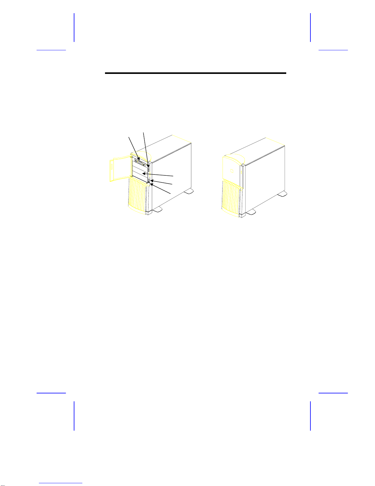
1.1 Front Panel
1 3.5-inch diskette drive
2 Power/Hard disk/RDM LEDs
3 5.25-inch drive bays
4 Power button
5 Reset button
12
3
5
4

2
Installation Guide
1.2 Rear Panel
1 Monitor power socket 7 Video port
2 Voltage selector 8 RJ-45 connector
3 Power socket 9 Universal serial bus (USB)
4 Mouse port connector
5 Keyboard port 10 Expansion board slots
6 Parallel port
1
2
10
9
8
7
6
5
4
3
IDT Housing
3
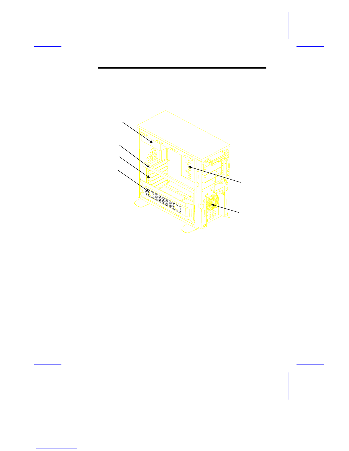
1.3 Internal Components
1 Power supply
2 CPU board support bar
3 Expansion board brackets
4 Metal frame for additional hard disks
5 5.25-inch drive bays (for hard disks or CD-ROM)
6 Speaker/Fan
1
3
4
5
6
2

4
Installation Guide
2 Positioning the Housing
2.1 As a Standalone System
When standing the housing as a standalone, pull out all the four legs
outward to stabilize the housing.
IDT Housing
5
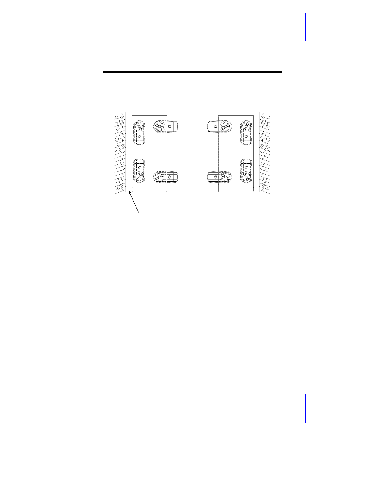
2.2 Against a Wall
The housing has vents on both sides, with the left vent being the more
important of the two. When standing the system with the vents facing a wall,
leave a 5-cm space from the wall to allow air circulation. See Figure A.
To stand the housing with the vents facing out, place the system close to the
wall and position the legs as in Figure B.
AB
5 cm

6
Installation Guide
3 Disassembly
If you have previously applied power to the system,
make sure to turn off the power and unplug the
power cord before opening the housing and installing
or removing any system component.
3.1 Removing the Front Panel
The system housing has a security lock on the front panel. Use the system
key to unlock the housing before proceeding with the disassembly.
1. Hold the right end of the front panel underside support and swing it to
the left.
2. Insert your hand in the opening under the front panel. Reach for the
panel handle and press it to release the cover from the housing frame.
3. Pull the cover to detach it completely from the housing frame.
IDT Housing
7
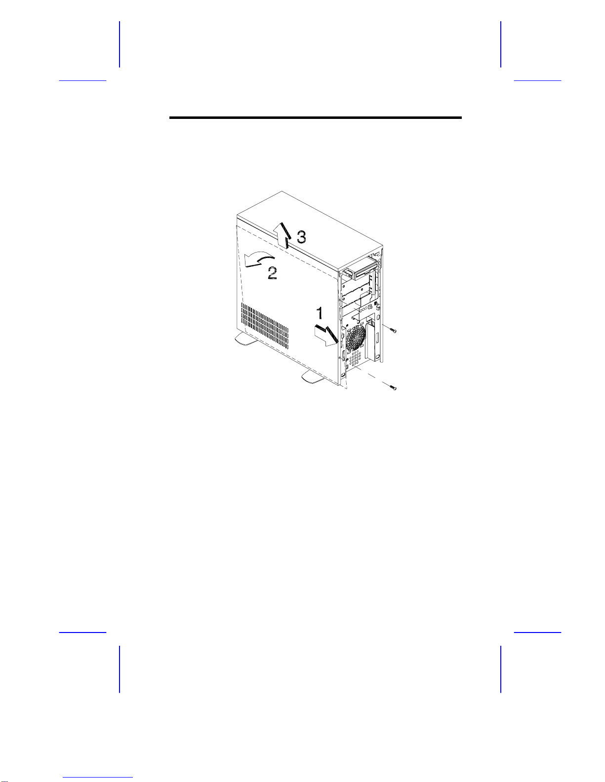
3.2 Removing the Left Cover
1. Remove the screws that secure the left cover, then slide the cover
toward the front for about an inch.
2. Pull the upper part of the cover outward.
3. Lift the cover out.

8
Installation Guide
3.3 Removing the Right Cover
1. Remove the screws that secure the right cover, then slide the cover
toward the front for about an inch.
2. Pull the upper part of the cover outward.
3. Lift the cover out.
IDT Housing
9
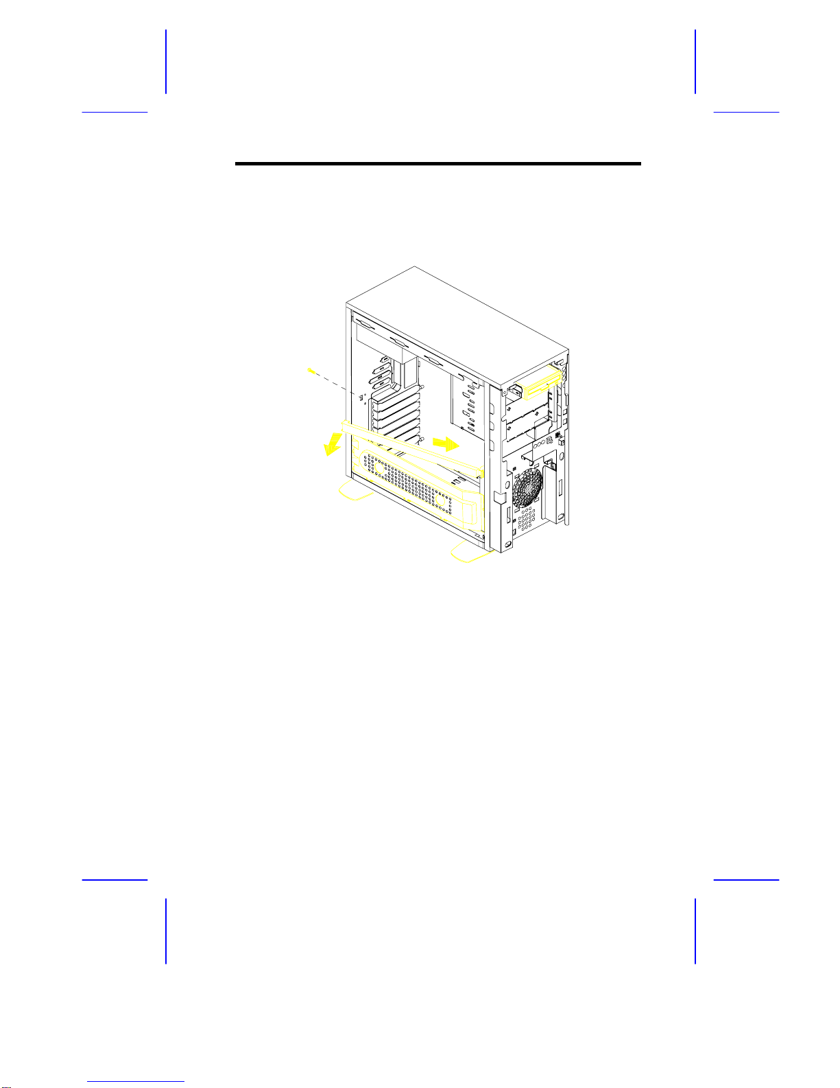
3.4 Removing the CPU Board Support Bar
1. Remove the screw that secures the CPU board support bar.
2. Firmly hold the support bar and push it toward the front for about an
inch. This releases the rear end of the support bar.
3. After releasing the rear end of the bar, carefully detach the front end
from the hook that secures it to the housing frame.
10
Installation Guide
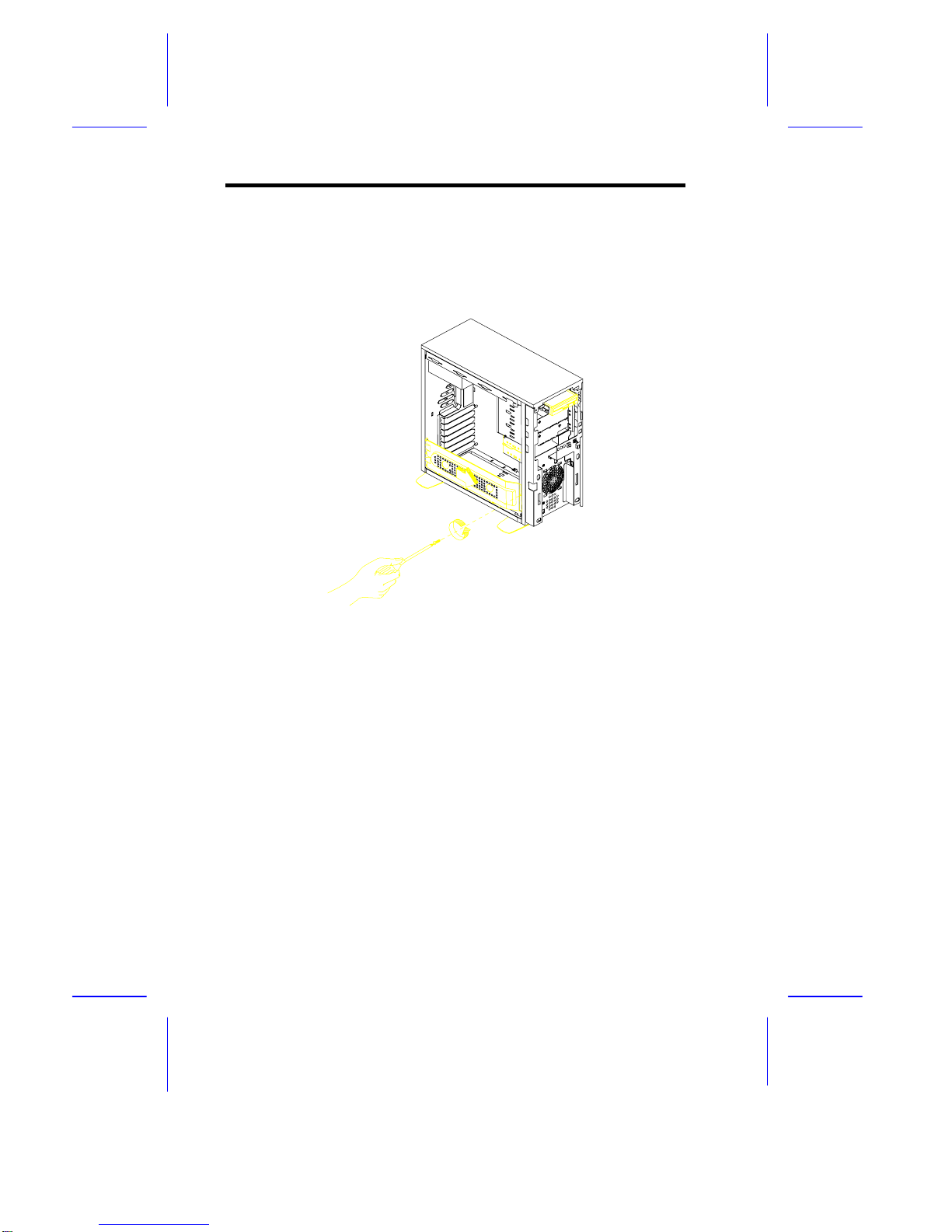
3.5 Removing the Metal Frame for Additional
Hard Disks
1. Remove the screw that secures the metal frame for additional hard
disk.
2. Slide the frame towards the direction of the arrow shown in the figure to
release the frame tabs from the slots on the floor of the housing.
Other manuals for IDT
1
Table of contents
Other Acer Computer Accessories manuals


