Acer AT2703 User manual

AT2703
Service Guide
PRINTED IN TAIWAN
Service guide files and updates are available
on the AIPG/CSD web; for more information,
please refer to http://csd.acer.com.tw

II
Revision History
Please refer to the table below for the updates made on AT2703 service guide.
Date Chapter Updates

III
Copyright
Copyright © 2006 by Acer Incorporated. All rights reserved. No part of this publication may be reproduced,
transmitted, transcribed, stored in a retrieval system, or translated into any language or computer language, in
any form or by any means, electronic, mechanical, magnetic, optical, chemical, manual or otherwise, without
the prior written permission of Acer Incorporated.
Disclaimer
The information in this guide is subject to change without notice.
Acer Incorporated makes no representations or warranties, either expressed or implied, with respect to the
contents hereof and specifically disclaims any warranties of merchantability or fitness for any particular
purpose. Any Acer Incorporated software described in this manual is sold or licensed "as is". Should the
programs prove defective following their purchase, the buyer (and not Acer Incorporated, its distributor, or its
dealer) assumes the entire cost of all necessary servicing, repair, and any incidental or consequential
damages resulting from any defect in the software.
Acer is a registered trademark of Acer Corporation.
Intel is a registered trademark of Intel Corporation.
Other brand and product names are trademarks and/or registered trademarks of their respective holders.

IV
Conventions
The following conventions are used in this manual:
Screen messages Denotes actual messages that appear
on screen.
NOTE Gives bits and pieces of additional
information related to the current
topic.
WARNING Alerts you to any damage that might
result from doing or not doing specific
actions.
CAUTION Gives precautionary measures to
avoid possible hardware or software
problems.
IMPORTANT Reminds you to do specific actions
relevant to the accomplishment of
procedures.

V
Preface
Before using this information and the product it supports, please read the following general information.
1. This Service Guide provides you with all technical information relating to the BASIC CONFIGURATION
decided for Acer's "global" product offering. To better fit local market requirements and enhance product
competitiveness, your regional office MAY have decided to extend the functionality of a machine (e.g.
add-on card, modem, or extra memory capability). These LOCALIZED FEATURES will NOT be covered
in this generic service guide. In such cases, please contact your regional offices or the responsible
personnel/channel to provide you with further technical details.
2. Please note WHEN ORDERING FRU PARTS, that you should check the most up-to-date information
available on your regional web or channel. If, for whatever reason, a part number change is made, it will
not be noted in the printed Service Guide. For ACER-AUTHORIZED SERVICE PROVIDERS, your Acer
office may have a DIFFERENT part number code to those given in the FRU list of this printed Service
Guide. You MUST use the list provided by your regional Acer office to order FRU parts for repair and
service of customer machines.

Chapter 1 1
Chapter1 System Specifications ...............................................1
Features . . . . . . . . . . . . . . . . . . . . . . . . . . . . . . . . . . . . . . . . . 1
Product Specification . . . . . . . . . . . . . . . . . . . . . . . . . . . . . . . 3
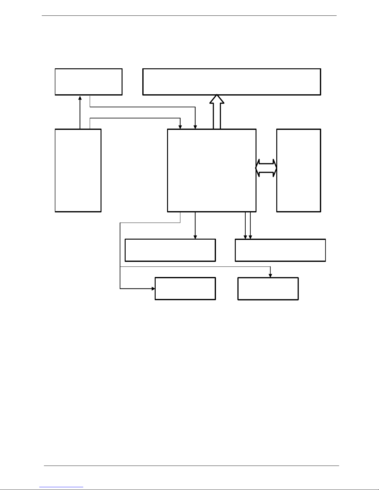
Block Diagram . . . . . . . . . . . . . . . . . . . . . . . . . . . . . . . . . . . . 4
LCD TV Overview . . . . . . . . . . . . . . . . . . . . . . . . . . . . . . . . . . 6
Bottom Panel View (for EMEA) . . . . . . . . . . . . . . . . . . . . . . . . 7
Bottom Panel View (for non EMEA). . . . . . . . . . . . . . . . . . . . . 8
Remote Control (for EMEA) . . . . . . . . . . . . . . . . . . . . . . . . . . 9
Remote Control (for non EMEA) . . . . . . . . . . . . . . . . . . . . . . 11
Basic Connection . . . . . . . . . . . . . . . . . . . . . . . . . . . . . . . . . 12
OSD Navigation . . . . . . . . . . . . . . . . . . . . . . . . . . . . . . . . . . 16
Empowering Technology . . . . . . . . . . . . . . . . . . . . . . . . . . . 19
Advanced Features . . . . . . . . . . . . . . . . . . . . . . . . . . . . . . . . 22
Dimensions . . . . . . . . . . . . . . . . . . . . . . . . . . . . . . . . . . . . . . 29
Source Options . . . . . . . . . . . . . . . . . . . . . . . . . . . . . . . . . . . 30
Chapter3 Machine Disassemblyand Replacement .............31
General Information . . . . . . . . . . . . . . . . . . . . . . . . . . . . . . . 32
Disassembly Procedure . . . . . . . . . . . . . . . . . . . . . . . . . . . . 33
Chapter4 Troubleshooting .....................................................41
Chapter6 FRU (Field Replaceable Unit) List .........................51
Exploded Diagram . . . . . . . . . . . . . . . . . . . . . . . . . . . . . . . . 52
Parts . . . . . . . . . . . . . . . . . . . . . . . . . . . . . . . . . . . . . . . . . . . 54

Chapter 1 1
Features
LCD Panel
• Max. resolution: 1366 x 768
• 16 CCFTs backlight system
• Display area: 27 inches diagonal
• Display color: 16.7 M colors
• Input signal: 1-ch LVDS
• Contrast ratio: 1000:1 (typical)
• Brightness: 500 Cd/m2(typical)
• Respond time: 8 ms (gray to gray)
• Viewing angle: 85o(L) / 85o(R), 85o(U) / 85o(D)
I/O functions
• RCA jack (YUV and CVBS) for YPbPr, YCbCr, video and audio
• 15-pin D-Sub for VGA
• DIN45325 (IEC169-2) terminal for TV / CATV input
• 3.5 mm earphone jack for audio line input
Video functions
• Support PAL / NTSC / SECAM video format
• Support 480i/576i, 480p/576p, 1080i and 720p format
• Built-in teletext functions
• Built-in dynamic adaptive smoothing filter
• Built-in dynamic temporal frame-filtering noise reduction
• Built-in dynamic motion and edge adaptive de-interlacing
• Film mode 3:2 & 2:2 pull down
• Screen display model 16:9 / 4:3 / panorama / zoom / PIP / POP
Mechanical
• VESA mounting holes
Multi-Sound System
• NICAM
• FM Stereo (A2)
Power Source
• Input voltage: 90 ~ 264V, 47 ~ 63Hz
• Input current: 1.8A
• Power consumption: 180W
• Stand-by: 5W max.
System Specifications
Chapter 1

2Chapter 1
Remote Controller
• Multi-function remote controller
Speaker
• Internal speaker: 10W x 2 stereo, adjustable volume
Environmental Requirement
• Operating temperature: 0 oC to 35 oC
• Operating humidity: 10% to 90% (non-condensing)
• Storage temperature: -20 oC to 60 oC
• Shipping temperature: -20 oC to 60 oC
• Storage humidity: 10% to 90% (non-condensing)
• Shipping humidity: 10% to 90% (non-condensing)
Others
• On screen display adjustment function
• ISP (In System Programming) function available for revising driver easily

Chapter 1 3
Product Specification
Model AT2703
Panel spec.
Resolution (pixels) 1366 x 768
Brightness (tpe.) 500 nits
Contrast Ratio (tpe.) 1000:1
Display color 16.7M
Viewing angle (tpe.) H: 176o; V: 176o
Response (tpe.) 8ms (gray to gray)
Power supply
Input 90V ~ 264V AC (47 ~ 63Hz)
Max. power consumption 150W
Power saving 5W
Mechanical
Dimensions (W x H x D mm) 854 x 527 x 207
Weight (Kg/lbs) 15.5/34.2
Gross Weight (Kg/lbs) 16.5/36.4
Wall Mounting (mm) 200 x 100
Analog TV system
TV color system PAL, SECAM
Sound system B/G/D/K/I/L (multi-European)
Stereo system NICAM/A2
TV Tuner system PLL, 45.25MHz ~ 862.25MHz
Subtitles Teletext 1.5
Analog TV-tuner quantity One
Terminal
Analog Tuner In Yes
SCART1 CVBS (In/Out), RGB (In), AudioR/L
SCART2 CVBS (In/Out), RGB (In), AudioR/L
AV3 in YPbPr, YCbCr, CVBS, AudioR/L
DVI in Yes(for AT2703/AT2704)
HDMI in Yes(for ATxx04)
PC D-sub in Yes
PC audio-in Yes
Audio system
Speaker 5W + 5W

4Chapter 1
Block Diagram
System Block & Wiring Diagram
I/O Board
Scart RGB
Scart RGB
Tuner
SPEAKER-L
IR & power button B
d
Key & Earphone Boar
d
SPEAKER-R
INVERTER
PANEL
Board
POWER
M
AIN Boar
d

Chapter 1 5
Block Diagram
PW328
DDR
DDR
FLASH
PW2300B
EEPROM
LCD
D-Sub
SDRAM
IN1
IN0
AUDIO Processor
MSP3415
Speaker
Amp.
TPA3100
R/L
Headphone
Amp.
TPA6110
Audio SW
744052
TA1218
AV Switch
AV1
AV2
S1
S2
R/G/B/H/V
TUNER
AV
S-Video
Video
Switch
743257
YPbPr1
SCART1
YPbPr2
SCART2
SCART RGB
AV2/S2
R/L
AV1/S1
R/L
TUNER
SIF
AV3/YPbPr
R/L
SIF
MB R/L
AUDIO Signal
PC IN
R/L
YPbPr3
YPbPr
AV3
AV3
IO R/L
IO R/L
Button & IR
LVDS
Audio
Switch
YPbPr2
R/L
YPbPr1
R/L
HDMI
SiI9011
HDMI R/L
I2S D/A
Audio
HDMI
IN0 to PW328
option

6Chapter 1
LCD TV Overview
Front Panel View
No. Description
1 Volume up/down
2 Input key
3 Menu key
4 Channel up/down
5 Headphone jack
1 Volume up When the OSD is on, functions the same as the Right arrow.
Volume down When the OSD is on, functions the same as the Left arrow.
2 Input key When the OSD is on, press this button to confirm selection.
3 Menu key Turns the OSD menu On and Off
4 Channel up When the OSD is on, functions the same as the Up arrow.
Channel down When the OSD is on, functions the same as the down arrow.
386+ 32:(5

Chapter 1 7
Bottom Panel View
(for EMEA)
No. Description Note
1 Power switch For AV3, Composite and component inputs share the same audio port.
* HDMI only for AT2604/AT2704/AT3204/AT3704
** DVI only for AT2604/AT2703/AT2704/AT3204/AT3704
2 AC-in
3 *HDMI-in
4VGA-in
5 **DVI-in
6 Audio-in
7AV-in
8 SCART x 2
9 Analog antenna-in
$7$7$7$7
$7
$7$7

8Chapter 1
Bottom Panel View
(for non EMEA)
No. Description Note
1 Power switch For AV3, Composite and component inputs share the same audio port.
* HDMI only for AT2604/AT2704/AT3204/AT3704
** DVI only for AT2604/AT2703/AT2704/AT3204/AT3704
2 AC-in
3 *HDMI-in
4VGA-in
5 **DVI-in
6 Audio-in
7 Component 1,2-in
8 AV 1,2-in
9 Analog antenna-in
$9
$9
69,'(2
&20321(17
&20321(17
$9
$9
69,'(2
&20321(17
&20321(17
$9
$9
69,'(2
&20321(17
&20321(17
$7$7$7$7
$7
$7$7

Chapter 1 9
Remote Control
(for EMEA)
1. Power: Press to turn on/off your TV.
2. Mute: Press to toggle audio on and off
3. VOL (up/down): Press this button to
increase or decrease the volume.
4. CH (up/down): Press this button to
sequentially select the TV channel.
5. Number keys
6. RECALL: Press to return to previous
channel.
7. ENTER: Press to confirm channel number
selection.
8. Input buttons (TV/AV/SCART/PC): Press
to select correct input mode.
9. SLEEP: Press to set a time period after
which the TV will switch itself to stand-by
(15, 30, 45, 60, 90)
10.FREEZE: Press to freeze the displayed
picture.
11.DISPLAY: Press to display input/channel
information (dependent on input/source
type).
12.WIDE: Press to toggle scaling mode
between 4:3, 16:9, Panorama and
Letterbox 1, 2, 3.
13.MENU: Press to open or close the Menu.
14.e (Empowering technology): Activate Acer
Empowering Technology.
15.Directional keys/OK
16.MPX: Press to select the sound input,
displayed in the top right-hand corner
(mono, stereo, bilingual).
17.PIP/PBP/POP: Switch between PIP/PBP/
POP mode.
18.SWAP: For PIP/PBP/POP mode, toggle
between the primary and subscreens.
19.ACTIVE: Toggle between primary and
subscreens.
20.SIZE/MODE: You can change subscreen
size in PIP mode. In POP mode, you can
switch POP mode from 1+5 to 1+12.
21.POSITION: In PIP mode, you can change
subscreen position.

10 Chapter 1
1. INDEX: Press to go to the index page.
2. SUBSTITLE: Press to view subtitles on
the screen.
3. REVEAL: Press to reveal hidden teletext
information.
4. TELETEXT: Press to switch from TV/AV to
Teletext mode.
5. SIZE: Press once to zoom teletext page to
2X. Press again to resume.
6. MIX: Press to overlay teletext page on the
TV image.
7. HOLD: Press to pause the current teletext
page in multi-page viewing mode.
8. SUBPAGE: Press to access the teletext’s
subpages directly.
9. Colour buttons (R/G/Y/B): Operates
corresponding button on the teletext page.

Chapter 1 11
Remote Control
(for non EMEA)
1. Power: Press to turn on/off your TV.
2. Mute: Press to toggle audio on and off
3. VOL (up/down): Press this button to
increase or decrease the volume.
4. CH (up/down): Press this button to
sequentially select the TV channel.
5. Number keys
6. RECALL: Press to return to previous
channel
7. ENTER: Press to confirm channel number
selection.
8. Input buttons (TV/AV/COMPONENT/PC):
Press to select correct input mode.
9. SLEEP: Press to set a time period after
which the TV will switch itself to stand-by
(15, 30, 45, 60, 90 or 120 mins)
10.FREEZE: Press to freeze the displayed
picture.
11.WIDE: Press to toggle scaling mode
between 4:3, 16:9, Panorama and
Letterbox 1, 2, 3
12.MENU: Press to open or close the Menu.
13.e (Empowering technology): Activate Acer
Empowering Technology.
14.Directional keys/OK
15.MTS: Press to select the sound input,
information is displayed in the top right-
hand corner (main, stereo, SAP).
16.PIP/PBP/POP: Switch between PIP/PBP/
POP modes.
17.SWAP: For PIP/PBP mode, toggle
between the primary and subscreens.
18.ACTIVE: Toggle between primary and
subscreens.
19.SIZE/MODE: You can change subscreen
size in PIP mode. In POP mode, you can
switch POP mode from 1+5 to 1+12.
20.POSITION: In PIP mode, you can change
subscreen position.
21.DISPLAY: Press to display input/channel
information(dependent on input/source type)
22.CC: Press to select close caption and text
service between CC1, CC2, CC3, CC4,
Text1, Te x t 2 , Te x t 3 , Text4.

12 Chapter 1
Basic Connection
Connecting the Power Cord
1. Connect the AC cord into the AC input on the back of the set.
2. Connect the plug to the wall outlet as shown.
(The power cord supplied varies according to your region)
Connecting an Antenna Cable
Connect the antenna cable to the appropriate antenna terminal on the back of the TV set as shown
below.
For EMEA:
For non EMEA:
$QDORJ
$9
$9
69,'(2
&20321(17
&20321(17
$QDORJ

Chapter 1 13
Connecting a DVD / VCR / STB / Audio / Video Equipment
Connect the DVD player, VCR or audio / video equipment using the SCART port located at the rear
of the LCD TV as shown.
For EMEA:
NOTE: Acer recommends the priority for connection: 1. HDMI 2. DVI 3. Component 2. SCART 3. Composite
**HDMI only for AT2604/AT2704/AT3204/AT3704
*** DVI only for AT2604/AT2703/AT2704/AT3204/AT3704
For non EMEA:
5
5
:
5
:
%*
5%*
<
<
$8',2
&20326,7(
&20321(17
6&$57
$9
$9
RU
'9' 9&5
67%
RU
+'0,
'6XE '9,
'6XE
'9,
'9,
<
<HOORZ
5HG
:KLWH
%OXH
*UHHQ
5
:
%
*
$9
$9
&20321(17
&20321(17
69,'(2
55
:
%*
&20321(17
55
:
%*
&20321(17LQ
$8',2
5
:
5
:
$8',2
6
69,'(2
6
<
<
$9LQ
&20326,7(
RU
'9' 9&5 67%
RU
+'0,
'6XE '9,
'6XE '9,
'9,
<
<HOORZ
5HG
:KLWH
%OXH
*UHHQ
6YLGHR
5
:
%
*
6

14 Chapter 1
Connecting a Camera / Camcorder / Video / Headphones
Connect the camera or camcorder to the video / audio ports on the bottom of the TV set as shown
below.
Connecting a Desktop / Notebook Computer
To display PC output on the LCD TV, connect the desktop or notebook computer to the TV as
shown below.
NOTE: For VGA and DVI input, Acer recommends setting your PC’s external monitor resolution to 1360 x 768
pixels @ 60Hz refresh rate.
DVI only for AT2604/AT2703/AT2704/AT3204/AT3704
Selecting the Input Source
Once you have connected your antenna or external equipment to the TV, you need to select the
correct input source. Press the corresponding button on the remote control to select the correct
input source.
'9, '6XE
'6XE
'9,
RU RU
Table of contents
Other Acer LCD TV manuals