1.3.4.2 Factory Assigned Display Modes
There are 17 factory pre-set frequency video
modes. These modes have a factory pre-set for all
characteristics affecting front-of-screen
performance. When the system is powered-
on,previously stored screen parameters for a pre-
defined mode will be recalled if the operating
mode is one of those stored in memory. If the
operating mode is not one of those stored in
memory, the monitor CPU will select the PRESET
timing for a mode that is the next lowest in
horizontal scanning frequency to the mode being
currently used. The screen parameters may be
adjusted by the use of the front bezel controls and
then may be saved as a user defined mode. The
monitor shall include all the preset video timings
shown in the following page.(Please see Note.(3) )
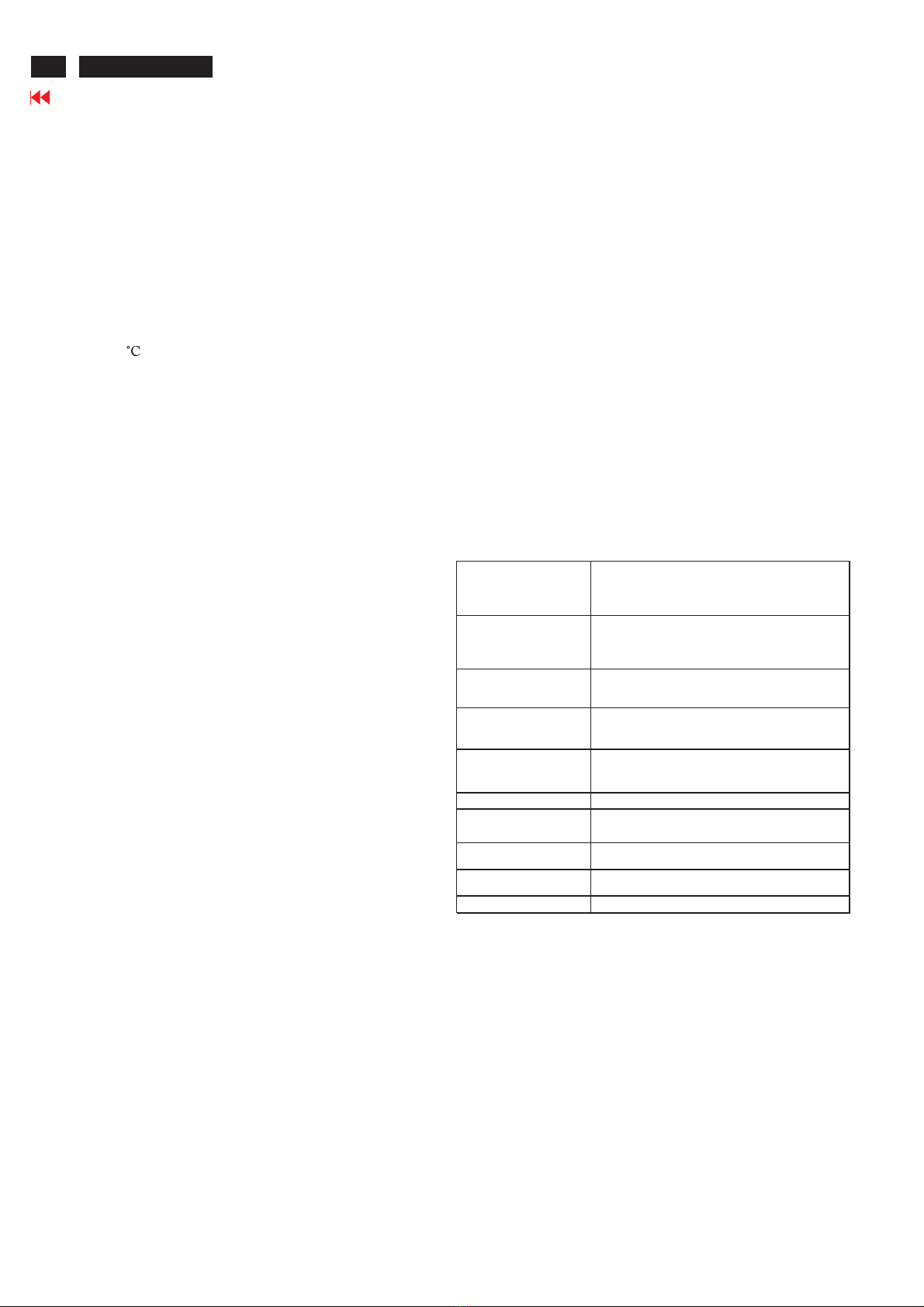
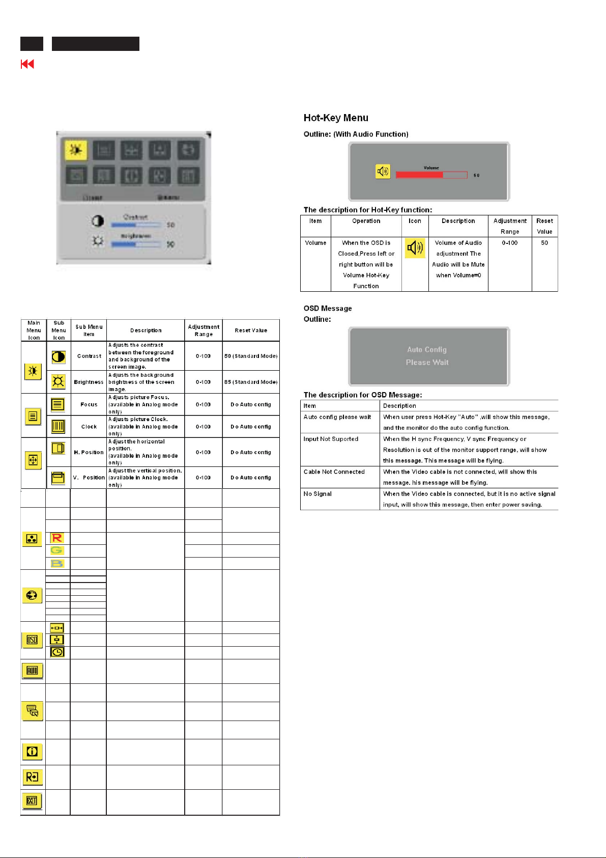
1.3.3.4 OSD adjustment
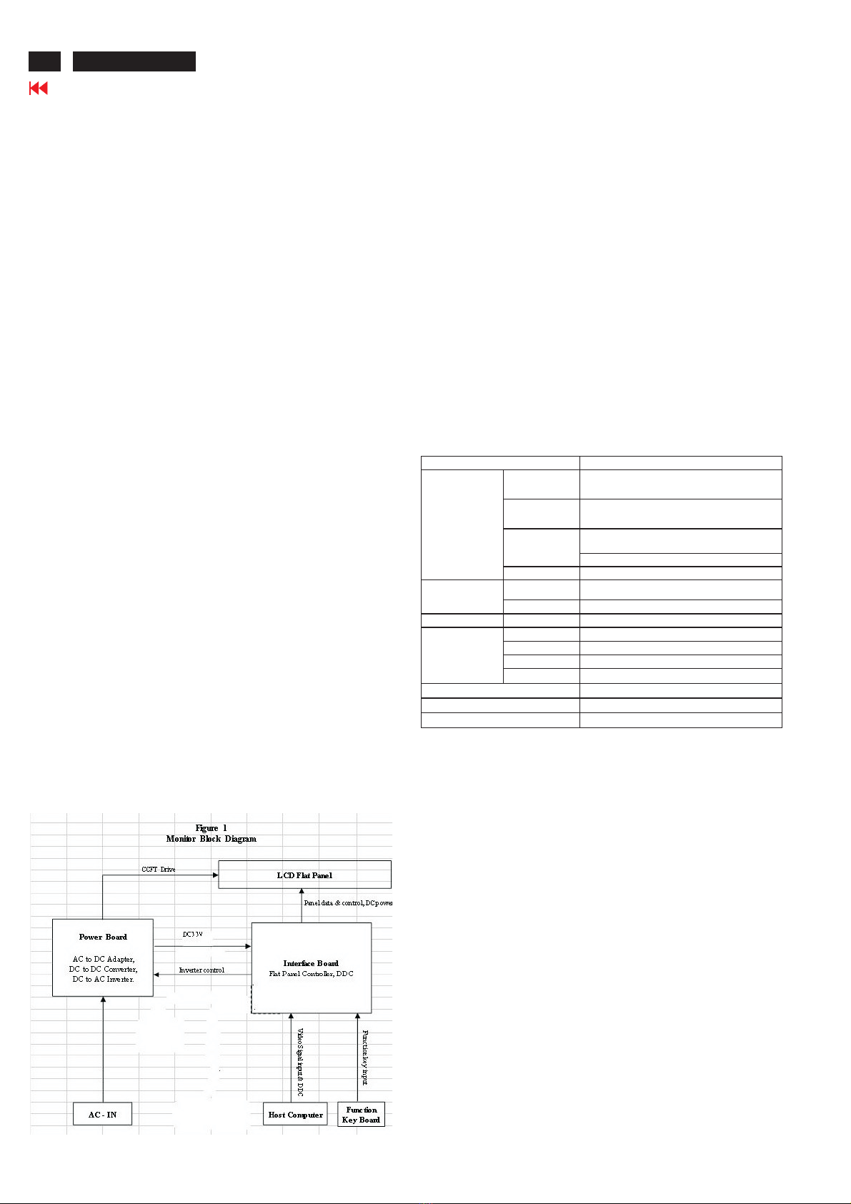
1. Product Specification (continued)
1.3.3.3 On-Screen Display
The Lite-ON On Screen Display system shall be
used , controlled by a Menu button. If the buttons
remain untouched for OSD turn off time while
displaying a menu , the firmware shall save the
current adjustments and exit. Also, if the video
controller changes video mode while the OSD is
active, the current settings shall be saved
immediately, the OSD turn off, and new video
mode is displayed.
ITEM CONTENT
AUDIO VOLUME To increase or decrease the sound level
BRIGHTNESS Back light Luminance of the LCD panel is adjusted.
CONTRAST A gain of R , G and B signal is adjusted.
AUTO CONTRAST A gain of R , G and B signal auto adjust.
CLOCK The ratio of dividing frequency of the dot clock is adjusted.
PHASE The phase of the dot clock is adjusted.
H-POSITION The indication screen is horizontally moved right and left (1 Pixels pitch).
V-POSITION The indication screen is vertically moved up and down (1 Pixels pitch).
AUTO ADJUST Clock system auto adjustment, about under 8 sec.
COLOR BALANCE Select three kinds of modes. ( USER /6500 / 9300 ).
OSD POSITION The OSD indication position can be adjusted.
OSD LANGUAGE Select the language used for the OSD menu among English , French ,
Italian , Deutsch and Spanish.
RECALL DEFAULTS All data copy from factory shipment data.
OSD DURATION Adjust OSD menu off time range from10~120 second.
POWER-SAVE Back light of the LCD panel is cut when the signal is not input (AC line
power consumption 2W or less).
INFORMATION The frequency of the horizontal / vertical synchronizing signal under the
input is indicated.
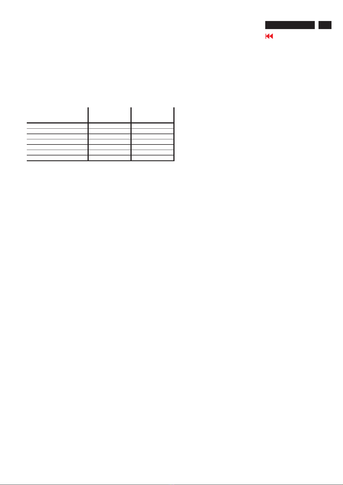
※NOTE : OSD MENU SEE APPENDIX A
Key When no OSD display OSD Displayed
1. To display the OSD menu on the screen.
2. To select the OSD sub-Menu
>Speaker Volume/Minus
(with Audio)
1. Back-forward selection of the OSD menu.
2. Decrease the value after sub-menu selected.
<Speaker Volume/Plus
(with Audio)
1. Forward selection of the OSD menu.
2. Increase the value after sub-menu selected.
Menu or sub.menu EXIT/Scenario mode
Auto Auto Adjust Function
Description
MENU Menu Display
1.3.4 Monitor Modes and Timing Capability
1.3.4.1 Format and Timing
The monitor shall synchronize with any vertical
frequency from 55 to 81K Hz , and with any
horizontal frequency from 30 to 94KHz. If the input
frequency is out of the above – specified range, the
monitor shall display a warning screen indicating
that the input frequency is out of range. Under no
circumstances shall any combination of input
signals cause any damage to the monitor .
1.3.4.4 User Display Modes
In addition to the factory pre-set video modes,
provisions shall be made to store up to 9 user
modes. If the current mode is a user mode, the
monitor shall select its previously stored settings.
If the user alters a setting, the new setting will be
stored in the same user mode. The user modes
are not affected by the pre-set command. If the
input signal requires a new user mode, storage of
the new format is automatically performed during
user adjustment of the display (if required, please
see Note.(4) )
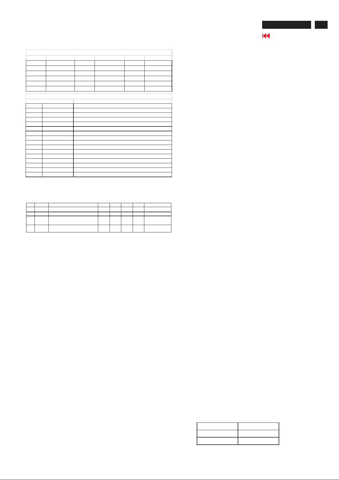
Preset timing Chart
1.3.4.3 Mode Recognition Pull-in
The monitor shall recognize preset modes within a
range of +/-1KHz whichever is less for horizontal ;
and within +/-1Hz for vertical.
H-Sync Band Width
(KHz) (MHz) H V
1 102 720 x 400 (70Hz) 31.469 28.322 - +
2 103 640 x 480 (59.94Hz) 31.469 25.175 - -
3 109 640 x 480 (75Hz) 37.5 31.5 - -
4 116 800 x 600 (60Hz) 37.879 40 + +
5 110 800 x 600 (75Hz) 46.875 49.5 + +
6 118 1024 x 768 (60Hz) 48.363 65 - -
7 141 1024 x 768 (75Hz) 60.023 78.75 + +
8 1280x800(60Hz) 49.306 71 + -
NOTE : (1) 76 ≦FV ≦86 : monitor can display but doesn't guarantee.
(2) fV < 55, or fV > 86 : warning invalid mode.
(3) Factory model :
After we first burn the code into the flash, every preset-model we run first must do auto-adjusting.
Then it'll not do auto-adjust again when we changed preset-mode back including AC on/off DC on/off.
The only way that preset-mode do auto-adjust again is press '' Internal Factory Reset''.
(4) User mode :
The code should memorize 9 timing mode exclusive of preset-modes as use mode and do auto-adjusting.
When user set a new mode that is not among previously. It'll do auto-adjusting then be solved to user modes.
The new mode will overwrite the first memorized user modes.
The user modes be cleared is same as Factory mode. Just do '' Internal Factory Reset''.
(5) Internal Factory Reset and OSD Factory Reset behavior.
Preset Timing Chart
Polarity
Item No Resolution
4
Go to cover page
ACER AL1516W