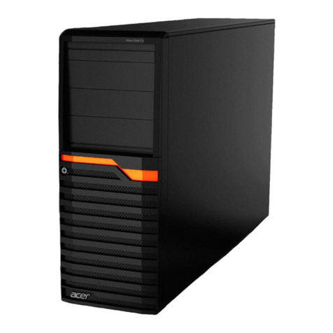
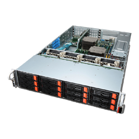
Acer HDS WMS100 User manual

MK-95DF738-01
|
Acer
|
HDS WMS100
User and Reference Guide


Acer | HDS WMS100™ User and Reference Guide iii
2005 Hitachi Data Systems Corporation, ALL RIGHTS RESERVED
Notice: No part of this publication may be reproduced or transmitted in any form or by any
electronic or mechanical means, including photocopying and recording, or stored in a
database or retrieval system for any purpose without the express written permission of
Hitachi Data Systems Corporation (hereinafter referred to as “Hitachi Data Systems”).
Hitachi Data Systems reserves the right to make changes to this document at any time
without notice and assumes no responsibility for its use. Hitachi Data Systems products and
services can only be ordered under the terms and conditions of Hitachi Data Systems’
applicable agreements. All of the features described in this document may not be currently
available. Refer to the most recent product announcement or contact your local Hitachi
Data Systems sales office for information on feature and product availability.
This document contains the most current information available at the time of publication.
When new and/or revised information becomes available, this entire document will be
updated and distributed to all registered users.
Trademarks
Hitachi Data Systems is a registered trademark and service mark of Hitachi, Ltd., and the
Hitachi Data Systems design mark is a trademark and service mark of Hitachi, Ltd.
Egenera and BladeFrame are registered trademarks of Egenera, Inc.
Emulex is a registered trademark of Emulex Corporation.
HP-UX, MC/ServiceGuard, and Tru64 are trademarks or registered trademarks of the
Hewlett-Packard Development Company, L.P.
AIX and RS/6000 are registered trademarks of International Business Machines Corporation.
Pentium is a registered trademark of Intel Corporation.
Linux is a registered trademark of Linus Torvalds.
Microsoft, Windows, and Windows NT are registered trademarks of Microsoft Corporation.
Netscape and Netscape Navigator are registered trademarks of Netscape Communications
Corporation in the U.S. and other countries.
NetWare is a registered trademark of Novell, Incorporated.
Oracle is a registered trademark of Oracle Corporation.
QLogic is a registered trademark of QLogic Corporation.
Java, Solaris, Sun, Sun Enterprise, and Sun Fire are trademarks of Sun Microsystems, Inc.
VERITAS is a trademark of VERITAS Software Corp.
iv Preface
All other brand or product names are or may be registered trademarks, trademarks, or
service marks of and are used to identify products or services of their respective owners.
Notice of Export Controls
Export of technical data contained in this document may require an export license from the
United States government and/or the government of Japan. Please contact the Hitachi Data
Systems Legal Department for any export compliance questions.
Document Revision Level
Revision Date Description
MK-95DF713-00 September 2005 Initial Release
MK-95DF713-01 November 2005 Revision 1, supersedes and replaces MK-95DF738-00
Source Document(s) for this Revision
SANRISE AMS100 (Workgroup Modular Storage) Series Disk Array Subsystem User’s Guide,
RSD-95DF738-03
Changes in this Revision
Added an introductory paragraph and table to the introduction of Chapter 1
Changed section 1.1
Changed section 1.1.2
Changed section 1.2
Added an introductory paragraph and table to the introduction of Chapter 2
Changed section 2.2.3.1
Changed section 2.4.6
Added Figure 2.4
Added Table 2.5
Changed Table 2.6
Changed Table 2.7
Changed Table 2.11
Changed Table 2.13
Changed Table 2.14
Added an introductory paragraph and table to the introduction of Chapter 3
Changed section 3.1.1

Acer | HDS WMS100™ User and Reference Guide v
Added section 3.1.3
Added an introductory paragraph and table to the introduction of Chapter 4
Changed section 4.2
Changed section 4.3
Changed section 4.3.1
Changed section 4.3.3
Changed section 4.3.4
Added section 4.4
Changed section 4.6.3
Added section 4.6.3.3
Changed section 4.6.4
Changed Figure 4.1
Added Figure 4.2
Changed Figure 4.3
Changed Figure 4.4
Changed Figure 4.5
Changed Figure 4.6
Changed Figure 4.7
Changed Figure 4.8
Changed Figure 4.11
Changed Figure 4.19
Changed Figure 4.20
Changed Figure 4.27
Changed Table 4.3
Changed Table 4.4
Changed Table 4.6
Changed Table 4.13
Added an introductory paragraph and table to the introduction of Chapter 5
Changed section 5.1
Added an introductory paragraph and table to the introduction of Chapter 6
Changed section 6.2
Added an introductory paragraph and table to the introduction of Chapter 7
Changed section 7.3.4

vi Preface
Changed section 7.3.6
Changed section 7.4
Changed section 7.8
Changed section 7.9
Added section 7.12
Added section 7.13
Added section 7.14
Added Figure 7.3
Added Figure 7.6
Added an introductory paragraph and table to the introduction of Chapter 8
Changed section 8.1
Changed section 8.1.1
Changed section 8.1.2
Changed section 8.1.3
Changed section 8.1.5
Changed section 8.3.1
Added section 8.3.7
Added section 8.5
Added section 8.6
Changed Figure 8.2
Added Figure 8.3
Changed Figure 8.4
Changed Figure 8.5
Changed Figure 8.7
Changed Figure 8.11
Changed Figure 8.12
Changed Table 8.5
Changed Table 8.11

Acer | HDS WMS100™ User and Reference Guide vii
Added an introductory paragraph and table to the introduction of the Appendices
Changed Table C.2
Added section D.2
Changed Table E.1
Changed Figure E.1
Changed Figure J.1
Added Figure J.2

viii Preface

Acer | HDS WMS100™ User and Reference Guide ix
Preface
This document describes the physical, functional, and operational characteristics of the
WMS100 subsystem. This document also provides operation instructions, installation details,
and configuration planning information for the WMS100 subsystem.
This User and Reference Guide assumes:
The user is familiar with the Acer | HDS AMS200/WMS100™ array subsystem, and
The user is familiar with the Windows®95, Windows®98, Windows®2000, or
Windows NT®operating systems. These versions are abbreviated to Windows in this
document.
This subsystem complies with FDA radiation performance standards 21CFR, subchapter J.
Notes:
For further information, please contact your Hitachi Data Systems account team, or visit
the Hitachi Data Systems worldwide web site at http://www.hds.com.
The use of Acer | HDS WMS100 subsystem and all other Acer | HDS products is governed
by the terms of your agreement(s) with Acer | HDS.
Software Version
This document revision applies to Acer | HDS AMS Products version 2.0 and higher.
EMI Regulation
This equipment has been tested and found to comply with the limits for a Class A digital
device, pursuant to Part 15 of the FCC Rules. These limits are designed to provide
reasonable protection against harmful interference when the equipment is operated in a
commercial environment. This equipment generates, uses, and can radiate radio frequency
energy and, if not installed and used in accordance with the instruction manual, may cause
harmful interference in which case the user will be required to correct the interference at
his own expense. Testing was done with shielded cables. Therefore, in order to comply with
the FCC regulations, you must use shielded cables with you installation.

x Preface
If trouble occurs in a different configuration, the user may be requested to take appropriate
preventive measures. The EMI test was done in the following configuration:
WMS100-RKXS+H1J
WMS100-RKXS+RKAJAT+H2J
Convention for Storage Capacity Values
This document uses the following convention for storage capacity values:
1 KB (kilobyte) = 1,000 bytes
1 MB (megabyte) = 1,000,000 bytes
1 GB (gigabyte) = 1,000,000,000 bytes
1 TB (terabyte) = 1,000 Gbytes
Referenced Documents
Acer | HDS AMS Cache Residency Manager Software User’s Guid
Acer | HDS Adaptable Modular Storage Storage Navigator Modular Graphical User Interface
(GUI) User’s Guide, MK-95DF711
Hitachi TagmaStore™ Adaptable Modular Storage Storage Navigator Modular Command Line
Interface (CLI), MK-95DF712
Hitachi TagmaStore™ Adaptable Modular Storage ShadowImage™In-System Replication
Software User’s Guide, MK-95DF709
Hitachi TagmaStore™ Adaptable Modular Storage TrueCopy™Synchronous Remote
Replication Software User’s Guide, MK-95DF710
Hitachi TagmaStore™ Adaptable Modular Storage Copy-on-Write SnapShot User’s Guide,
MK-95DF708
Acer | HDS Global 19-Inch Rack Reference Guide
Hitachi TagmaStore™Adaptable Modular Storage Performance Monitor Software User’s
Guide, MK-95DF706

Acer | HDS WMS100™ User and Reference Guide xi
Comments
Please send us your comments on this document. Make sure to include the document title,
number, and revision. Please refer to specific section(s) and paragraph(s) whenever possible.
E-mail: [email protected]
Fax: 858-695-1186
Mail:
Technical Writing, M/S 35-10
Hitachi Data Systems
10277 Scripps Ranch Blvd.
San Diego, CA 92131
Thank you! (All comments become the property of Hitachi Data Systems Corporation.)

xii Preface

Acer | HDS WMS100™ User and Reference Guide xiii
Contents
Chapter 1 Overview of the WMS100 Subsystem...................................................................................1
1.1 Overview Features ...............................................................................2
1.1.1 High Data Availability...................................................................2
1.1.2 Connectivity..............................................................................2
1.1.3 Scalability ................................................................................3
1.1.4 Performance Reporting and Monitoring..............................................3
1.1.5 Reliability, Availability, and Serviceability .........................................4
1.2 Rack-Mount Model................................................................................5
1.3 Floor Model........................................................................................6
Chapter 2 Planning for Installation and Operation................................................................................7
2.1 User Responsibilities .............................................................................9
2.2 Safety Precautions ............................................................................. 10
2.2.1 Warning Labels......................................................................... 11
2.2.2 Repair, Modification, and Disassembly............................................. 11
2.2.3 Precautions for Using Equipment ................................................... 11
2.2.4 Inspection and Cleaning Precautions............................................... 15
2.2.5 Emergency Precautions............................................................... 16
2.2.6 Warning Notices ....................................................................... 17
2.2.7 Warning Label Locations ............................................................. 17
2.3 General Specifications and Requirements.................................................. 23
2.3.1 Dimensions and Weigh................................................................ 23
2.3.2 Service Clearance Requirements.................................................... 25
2.3.3 Floor Load Rating...................................................................... 26
2.3.4 Internal Logic Specifications......................................................... 27
2.3.5 Cable Function......................................................................... 27
2.4 Environmental Specifications and Requirements.......................................... 28
2.4.1 Environmental Hazards............................................................... 28
2.4.2 Temperature and Humidity Requirements ........................................ 29
2.4.3 Input Power and Insulation Performance Specifications ........................ 29
2.4.4 Air Flow Requirements ............................................................... 30
2.4.5 Vibration and Shock Tolerances..................................................... 31
2.4.6 Reliability............................................................................... 32
Chapter 3 Powering On/Off Procedure.................................................................................................35
3.1 WMS100 Rack-Mount Model ................................................................... 36
3.1.1 Subsystem Power On.................................................................. 36
3.1.2 Subsystem Power Off ................................................................. 38
3.1.3 Stop/Start/Restart of the NAS OS .................................................. 38
3.2 WMS100 Floor Model ........................................................................... 40
3.2.1 Subsystem Power On.................................................................. 40
3.2.2 Subsystem Power Off ................................................................. 41
Chapter 4 Subsystem Architecture and Components........................................................................43
4.1 Configuration Block Diagrams ................................................................ 44
4.1.1 WMS100 Rack-Mount Model .......................................................... 44

xiv Contents
4.1.2 WMS100 Floor Model .................................................................. 49
4.2 Redundant Power Supplies.................................................................... 53
4.3 Fibre Channel Interface ....................................................................... 54
4.3.1 Mini-HUB54
4.3.2 Connection Specifications............................................................ 55
4.3.3 Fibre Channel Configuration......................................................... 57
4.3.4 Attention to the Host Direct Connection for WMS100........................... 57
4.4 Ethernet Interface.............................................................................. 58
4.5 Array Frame ..................................................................................... 58
4.5.1 WMS100 Rack-Mount Model .......................................................... 59
4.5.2 Floor Model............................................................................. 60
4.6 Component Names, Locations, and Functions ............................................. 61
4.6.1 Front Bezel Component Locations and Functions ................................ 62
4.6.2 Component Locations................................................................. 64
4.6.3 Switch Locations and Functions..................................................... 65
4.6.4 Connector Locations and Functions ................................................ 67
4.6.5 LED Locations and Functions ........................................................ 70
Chapter 5 Functional and Operational Characteristics ......................................................................79
5.1 New WMS100 Features and Capabilities .................................................... 81
5.2 RAID Implementations ......................................................................... 82
5.3 Cache Management............................................................................. 84
5.4 Logical Units (LUs).............................................................................. 86
5.5 Open Systems Features and Functions ...................................................... 88
5.5.1 Open Systems Middleware ........................................................... 88
5.5.2 LUN Management...................................................................... 88
5.6 Data Management Features and Functions ................................................. 89
5.6.1 Cache Residency Manager Function ................................................ 89
5.6.2 LUN Manager Function................................................................ 89
5.6.3 Data Retention Utility Function..................................................... 89
5.6.4 LUN Expansion Function.............................................................. 89
5.6.5 Password Protection Function....................................................... 89
5.7 Copy Solution Features and Functions ...................................................... 90
5.7.1 ShadowImage In-System Replication Function.................................... 90
5.7.2 Copy-On-Write Snapshot Function.................................................. 90
5.7.3 NAS Backup Restore Modular Function............................................. 90
5.7.4 NAS SyncImage Modular Function................................................... 90
5.8 Performance Management Features and Functions ....................................... 91
5.8.1 Performance Monitor Function...................................................... 91
5.8.2 Cache Partition Manager Function.................................................. 91
5.9 NAS Features and Functions .................................................................. 92
5.9.1 NAS Data Control Modular Function ................................................ 92
5.9.2 NAS File Sharing Modular Function ................................................. 92
5.9.3 NAS Manager Modular Function ..................................................... 92
5.9.4 NAS Backup Restore Modular Function............................................. 92
5.9.5 NAS SyncImage Modular Function................................................... 92
5.9.6 NAS Anti-Virus Agent Modular Function............................................ 92

Acer | HDS WMS100™ User and Reference Guide xv
Chapter 6 Configuring the WMS100 Subsystem.................................................................................93
6.1 Overview of Configuration .................................................................... 95
6.1.1 Open Systems Configuration......................................................... 95
6.1.2 Defining LUNs .......................................................................... 95
6.1.3 Fibre Channel Interface Addressing ................................................ 96
6.1.4 Alternate Pathing...................................................................... 98
6.1.5 NAS Configuration..................................................................... 99
6.2 Configuring LAN Interfaces of the WMS100 Subsystem ..................................100
6.3 Configuring the WMS100 Subsystem ........................................................101
6.4 Registering the WMS100 Subsystem for Control by Storage Navigator Modular .....102
6.5 Configuring the WMS100 Subsystem for the Desired Application ......................103
6.6 WMS100 Subsystem General Configuration................................................104
Chapter 7 Configuring Storage on the WMS100 Subsystem............................................................105
7.1 Software Composition ........................................................................107
7.1.1 Microprogram .........................................................................107
7.1.2 System Parameters................................................................... 107
7.1.3 Configuration Information ..........................................................107
7.1.4 SNMP Information ....................................................................107
7.1.5 Storage for Parameters..............................................................108
7.2 Setting Fibre Channel Information..........................................................109
7.3 Determining Space and RAID Level Requirements........................................111
7.3.1 Setting a Spare Disk..................................................................112
7.3.2 Canceling a Spare Disk Setting .....................................................115
7.3.3 Setting a RAID Group................................................................. 116
7.3.4 Deleting a RAID Group............................................................... 119
7.3.5 Setting a Logical Unit................................................................121
7.3.6 Deleting the Last Logical Unit......................................................123
7.3.7 Formatting a Logical Unit...........................................................125
7.3.8 Changing the Format Mode .........................................................129
7.3.9 Changing the Default Controller in Charge of an LU............................131
7.4 Setting Host Group Information............................................................. 132
7.4.1 Setting Mapping Information .......................................................132
7.5 Transferring Configurations from One Array to Another ................................136
7.6 Storing Configuration Data................................................................... 137
7.6.1 System Parameter Information.....................................................137
7.6.2 RAID Group/LU information ........................................................138
7.6.3 Port/Host Group Information.......................................................140
7.6.4 NAS System LU/User LU information..............................................141
7.7 Applying Configuration Data to Another WMS100 Subsystem...........................142
7.7.1 System Parameters................................................................... 142
7.7.2 RAID Group/Logical unit............................................................. 143
7.7.3 Port/Host Group......................................................................144
7.8 Setting Host Connection Parameters....................................................... 145
7.8.1 Simple Setting ........................................................................145
7.8.2 Detailed Setting ...................................................................... 150
7.9 Setting the Subsystem when using Special Mode......................................... 151
7.10 Changing the Network Parameter...........................................................153
7.11 Setting the System LU and User LU in the NAS System.................................. 155

xvi Contents
7.11.1 Setting the System LU ...............................................................155
7.11.2 Setting the User LU ..................................................................157
7.12 Setting the System LU and User LU in the NAS System.................................. 159
7.12.1 Setting the System LU ...............................................................160
7.12.2 Setting the User LU ..................................................................162
7.13 Setting the NNC Management LAN Port Information in the NAS System..............164
7.14 Setting the Time Zone........................................................................167
Chapter 8 Troubleshooting.................................................................................................................171
8.1 Troubleshooting Based on LED Indications ................................................173
8.1.1 The POWER LED Does Not Turn On ................................................173
8.1.2 The POWER LED Has Turned off....................................................174
8.1.3 If the READY LED Does NotTurn On or has Turned On Once then Off........175
8.1.4 The Alarm LED Has Turned On .....................................................176
8.1.5 The WARNING LED Has Turned On or Blinks......................................177
8.2 Web Overview..................................................................................178
8.2.1 Operational Environment ...........................................................178
8.2.2 Characteristics of Network Functions.............................................181
8.3 Web Operational Procedures ................................................................182
8.3.1 Connecting to the Network using a LAN Interface ..............................182
8.3.2 Screen Outlines.......................................................................183
8.3.3 Main Screen in Normal Mode .......................................................186
8.3.4 Status Display of Replaceable Components ...................................... 189
8.3.5 Information Message.................................................................197
8.3.6 Setting the Buzzer Sound Volume..................................................198
8.3.7 Clear Specified Factors of NNC Partial Alarm....................................199
8.4 Troubleshooting Using a Web Connection .................................................202
8.4.1 Checking Subsystem Status .........................................................202
8.4.2 Checking the Progress Condition Display .........................................203
8.4.3 Checking Component Status........................................................204
8.4.4 Checking Log Messages .............................................................. 205
8.4.5 Troubleshooting Using Messages ...................................................207
8.4.6 Reading Failure Information........................................................ 213
8.5 Determining the Failure of the Network Side in the NAS System......................215
8.6 Connecting Failure in Connection with the Web .........................................217
8.6.1 Collecting Simple Trace.............................................................217
8.6.2 NAS Log Collection ...................................................................220
8.6.3 NAS Dump Generation ...............................................................223
Appendix A Glossary..............................................................................................................................231
Appendix B System Parameter Settings List........................................................................................237
Appendix C Basic Specifications of the Subsystem............................................................................249
Appendix D Interfaces ............................................................................................................................255
D.1 Fibre Channel Connection Specifications.................................................. 255
D.2 Ethernet Connection Specifications ........................................................283

Acer | HDS WMS100™ User and Reference Guide xvii
Appendix E Remote Adapter Specifications.........................................................................................285
E.1 Remote Adapter Specifications..............................................................285
E.2 Remote Adapter Dimensions................................................................. 286
Appendix F List of Storage Capacities Corresponding to RAID Levels and Configurations...........287
Appendix G Port Address Mapping Table.............................................................................................295
Appendix H Power Cables......................................................................................................................299
Appendix I Number of Logical Blocks.................................................................................................301
Appendix J Using LUN Security or LUN Management on a Fabric Switch Connection...................305
J.1 When an FC Interface Board is Not Added to the Control Unit.........................305
J.2 When an FC Interface Board is Added to the Control Unit..............................306

xviii Contents
List of Figures
Figure 2.1 Position of Labels on Floor Model RKXS+H1J......................................... 18
Figure 2.2 Position of Labels on Floor Model RKXS+RKAJAT+H2J .............................. 19
Figure 2.3 Position of Labels on Rack-Mount Model RKXS....................................... 20
Figure 2.4 Position of Labels on Rack-Mount Model RKNAS..................................... 21
Figure 2.5 Position of Labels on Rack-Mount Model RKAJAT ................................... 22
Figure 3.1 Subsystem Power On/Off (Example: Floor [RKXS+ RKAJ+H2J) .................... 41
Figure 4.1 RKXS System Configuration (When the FC Interface board is not added) ....... 45
Figure 4.2 RKXS and System Configuration (When the FC Interface board is added)...... 46
Figure 4.3 RKXS and RKNAS System Configuration ............................................... 47
Figure 4.4 RKAJAT System Configuration.......................................................... 48
Figure 4.5 Floor (RKXS+H1J) Model WMS100 System Configuration (When FC Interface
board is not added) ...................................................................... 49
Figure 4.6 Floor (RKXS+RKAJAT+H2J) Model WMS100 System Configuration (When FC
Interface board is added)............................................................... 50
Figure 4.7 Floor (RKXS+RKAJAT+H2J) Model WMS100 System Configuration (When FC
Interface board is not added) .......................................................... 51
Figure 4.8 Floor (RKXS+RKAJAT+H2J) Model WMS100 System Configuration (When FC
Interface board is added)............................................................... 52
Figure 4.9 WMS100 FC Connector................................................................... 54
Figure 4.10 Front Bezel Component Locations..................................................... 62
Figure 4.11 Front Bezel LED Locations .............................................................. 63
Figure 4.12 RKXS Component Locations............................................................. 64
Figure 4.13 RKAJAT Component Locations.......................................................... 64
Figure 4.14 Panel Assembly Switch Location....................................................... 65
Figure 4.15 Power Unit Switch Locations ........................................................... 66
Figure 4.16 RKNAS Switch Locations................................................................. 66
Figure 4.17 SENC Unit Connector Locations ....................................................... 67
Figure 4.18 Power Unit Connector Locations...................................................... 67
Figure 4.19 Control Unit Connector Locations..................................................... 68
Figure 4.20 RKNAS Connector Locations............................................................ 69
Figure 4.21 Disk Drive Display LED Locations...................................................... 70
Figure 4.22 Disk Drive Display (RKAJAT) LED Locations.......................................... 72
Figure 4.23 Battery Backup Unit LED Locations................................................... 72
Figure 4.24 SENC Unit LED Locations ................................................................ 73
Figure 4.25 Power Unit LED Locations.............................................................. 74
Figure 4.26 Fan Assembly LED Locations............................................................ 74
Figure 4.27 Control Unit LED Locations............................................................. 75
Figure 4.28 RKNAS (front) Connector Locations................................................... 77
Figure 4.29 RKNAS (rear) LED Locations........................................................... 78
Figure 5.1 Logical Units (When FC interface board is not added to the control unit)...... 86
Figure 5.2 Logical Units (When FC interface board is added to the control unit)........... 86
Figure 5.3 Logical Units (NAS Unit)................................................................. 87
Figure 6.1 Fibre Channel Port-to-LUN Addressing (When FC interface board is not added to
the control unit).......................................................................... 96
Figure 6.2 Fibre Channel Port-to-LUN Addressing (When FC interface board is added to the
control unit)............................................................................... 97
Figure 6.3 Alternate Pathing ........................................................................ 98
Figure 7.1 Fibre Channel Setting................................................................... 110

Acer | HDS WMS100™ User and Reference Guide xix
Figure 7.2 Logical Status Tab.......................................................................116
Figure 7.3 Logical Status Tab (NAS) ...............................................................117
Figure 7.4 RAID Group Dialog Box..................................................................117
Figure 7.5 RAID Group is Updated .................................................................118
Figure 7.6 RAID Group is Updated (NAS).......................................................... 118
Figure 7.7 Setting the Logical Unit Dialog Box...................................................122
Figure 8.1 LAN Connector Location................................................................182
Figure 8.2 Main Screen Outline..................................................................... 183
Figure 8.3 Main Screen Outline..................................................................... 184
Figure 8.4 Subsystem Condition Display ..........................................................186
Table 8.5 Patrol Lamp Display..................................................................... 187
Table 8.6 Exchange Parts Status Display......................................................... 188

xx Contents
List of Tables
Table 2.1 Caution Statements...................................................................... 17
Table 2.2 Symbols Contained in Warning Labels................................................. 17
Table 2.3 WMS100 Dimensions and Weight of Rack-Mount Model............................. 23
Table 2.4 WMS100 Dimensions and Weight of Floor Model..................................... 23
Table 2.5 WMS100 Dimensions and Weight of NAS Unit ........................................ 24
Table 2.6 Internal Logic Specification of WMS100 Rack-Mount Model ....................... 27
Table 2.7 Principal Functions of WMS100 Cables................................................ 27
Table 2.8 Environmental Specifications........................................................... 29
Table 2.9 Input Power and Insulation Performance Specifications for Rack-Mount Model
(RKXS)...................................................................................... 29
Table 2.10 Input Power and Insulation Performance Specifications for Floor Model........ 30
Table 2.11 Input Power and Insulation Performance Specifications for the NAS Unit ...... 30
Table 2.12 Vibration and Shock Tolerances........................................................ 31
Table 2.13 Reliability of WMS100 Rack-Mount Model............................................. 32
Table 2.14 Reliability of WMS100 Floor Model..................................................... 33
Table 4.1 Available Host Connectors of Each Topology Setting and Connection/Method. 55
Table 4.2 Available Host Connectors of Each Topology Setting and Connection/Method. 56
Table 4.3 Basic Specifications of Rack-Mount Model............................................ 59
Table 4.4 Basic Specifications of the Floor Model............................................... 60
Table 4.5 Front Bezel Component Functions..................................................... 62
Table 4.6 Front Bezel LED Functions .............................................................. 63
Table 4.7 Panel Assembly Switch Functions...................................................... 65
Table 4.8 Power Unit Switch Functions ........................................................... 66
Table 4.9 RKNAS Switch Functions................................................................. 66
Table 4.10 Power Unit Connector Functions....................................................... 67
Table 4.11 Power Unit Connector Functions....................................................... 68
Table 4.12 Control Unit Connector Functions ..................................................... 68
Table 4.13 RKNAS Connector Functions ............................................................ 69
Table 4.14 Disk Drive Display LED Functions....................................................... 71
Table 4.15 Disk Drive Display (RKAJAT) LED Functions .......................................... 72
Table 4.16 Battery Backup Unit LED Functions.................................................... 72
Table 4.17 SENC Unit LED Functions................................................................ 73
Table 4.18 Power Unit LED Functions............................................................... 74
Table 4.19 Fan Assembly LED Functions............................................................ 74
Table 4.20 Control Unit LED Functions ............................................................. 75
Table 4.21 RKNAS (front) Connector Functions ................................................... 77
Table 4.22 RKNAS (rear) LED Functions ............................................................ 78
Table 5.1 Rack-Mount RAID Specifications........................................................ 83
Table 5.2 Floor Model RAID Specifications........................................................ 83
Table 5.3 Rack-Mount Model Cache Specifications.............................................. 84
Table 5.4 Floor Model Cache Specifications...................................................... 85
Table 7.1 Storage for Parameters................................................................. 108
Table 7.2 Formatting Message..................................................................... 128
Table 7.3 Simple Setting Item List................................................................146
Table 7.4 Simple Setting Item List................................................................147
Table 7.5 Additional Parameter Setting Items..................................................147
Table 7.6 List of Additional Parameter Setting Items .........................................159
Table 8.1 Web Operational Environment ........................................................178
Table of contents
Other Acer Server manuals

Acer
Acer Altos 11000 System User manual

Acer
Acer Veriton N2110G User manual

Acer
Acer AT350 F2 Series User manual

Acer
Acer Extensa 500 Parts list manual

Acer
Acer Altos 1200 User manual

Acer
Acer AW2000h-AW170h User manual

Acer
Acer Altos G5350 User manual

Acer
Acer Ferrari 1100 Series User manual

Acer
Acer AT310 F1 Series User manual

Acer
Acer ALTOS R910 Series User manual

Acer
Acer AR360 F1 Series User manual

Acer
Acer WT 300 User manual

Acer
Acer Altos R480 F4 User manual

Acer
Acer AR320 F2 User manual

Acer
Acer Altos G5450 Series User manual

Acer
Acer Altos G710 User manual

Acer
Acer 700id User manual

Acer
Acer Altos R920 Series User manual

Acer
Acer AT110 F2 User manual

Acer
Acer Altos R520 M2 User manual